EP0596183B1 - Unterwasseranlage zum Befüllen von Behältern - Google Patents
Unterwasseranlage zum Befüllen von Behältern Download PDFInfo
- Publication number
- EP0596183B1 EP0596183B1 EP92830614A EP92830614A EP0596183B1 EP 0596183 B1 EP0596183 B1 EP 0596183B1 EP 92830614 A EP92830614 A EP 92830614A EP 92830614 A EP92830614 A EP 92830614A EP 0596183 B1 EP0596183 B1 EP 0596183B1
- Authority
- EP
- European Patent Office
- Prior art keywords
- bell
- water
- bin
- fruit
- loading
- Prior art date
- Legal status (The legal status is an assumption and is not a legal conclusion. Google has not performed a legal analysis and makes no representation as to the accuracy of the status listed.)
- Expired - Lifetime
Links
Images

Classifications
-
- B—PERFORMING OPERATIONS; TRANSPORTING
- B65—CONVEYING; PACKING; STORING; HANDLING THIN OR FILAMENTARY MATERIAL
- B65G—TRANSPORT OR STORAGE DEVICES, e.g. CONVEYORS FOR LOADING OR TIPPING, SHOP CONVEYOR SYSTEMS OR PNEUMATIC TUBE CONVEYORS
- B65G51/00—Conveying articles through pipes or tubes by fluid flow or pressure; Conveying articles over a flat surface, e.g. the base of a trough, by jets located in the surface
- B65G51/01—Hydraulic transport of articles
-
- B—PERFORMING OPERATIONS; TRANSPORTING
- B65—CONVEYING; PACKING; STORING; HANDLING THIN OR FILAMENTARY MATERIAL
- B65B—MACHINES, APPARATUS OR DEVICES FOR, OR METHODS OF, PACKAGING ARTICLES OR MATERIALS; UNPACKING
- B65B25/00—Packaging other articles presenting special problems
- B65B25/02—Packaging agricultural or horticultural products
- B65B25/04—Packaging fruit or vegetables
- B65B25/045—Packaging fruit or vegetables by flotation means
-
- B—PERFORMING OPERATIONS; TRANSPORTING
- B65—CONVEYING; PACKING; STORING; HANDLING THIN OR FILAMENTARY MATERIAL
- B65G—TRANSPORT OR STORAGE DEVICES, e.g. CONVEYORS FOR LOADING OR TIPPING, SHOP CONVEYOR SYSTEMS OR PNEUMATIC TUBE CONVEYORS
- B65G69/00—Auxiliary measures taken, or devices used, in connection with loading or unloading
- B65G69/16—Preventing pulverisation, deformation, breakage, or other mechanical damage to the goods or materials
-
- B—PERFORMING OPERATIONS; TRANSPORTING
- B65—CONVEYING; PACKING; STORING; HANDLING THIN OR FILAMENTARY MATERIAL
- B65G—TRANSPORT OR STORAGE DEVICES, e.g. CONVEYORS FOR LOADING OR TIPPING, SHOP CONVEYOR SYSTEMS OR PNEUMATIC TUBE CONVEYORS
- B65G2201/00—Indexing codes relating to handling devices, e.g. conveyors, characterised by the type of product or load being conveyed or handled
- B65G2201/02—Articles
- B65G2201/0202—Agricultural and processed food products
- B65G2201/0211—Fruits and vegetables
Definitions
- the invention relates to an underwater bin-filling plant.
- Plants of the kind in object are used in harvest collection and sorting centres.
- the fruit worked in such plants are generally constituted by apples, oranges and similar.
- fruit arriving from the fields is tipped on to sorting lines on which the fruit is selected according to size and characteristics, unsuitable fruit being eliminated. Then fruit of one type (of the same size) is placed in large bins in order to be sent for distribution or conservation.
- the fruit is transported by means of transport channels on which the fruit floats and is carried to a removal zone; these plants generally have a considerable number of transport channels, each of which conveys fruit of different characteristics which are to be placed in different bins.
- a bell is envisaged at the removal area, which bell's open end is immersed in water; under the bell there is an empty bin which is also immersed in water.
- transport means of known type and generally constituted by bucket conveyors or the like, the fruit is removed at the removal zone and conveyed downwards below the free surface of the water, and inserted, still under water, inside the bell.
- the fruit floats in the water contained in the bell; once there is the desired quantity of fruit inside the bell, the bin positioned under the bell is raised and in its upcoming movement raises also the bell; when the bin has emerged from the water, the bell, which at this point is above the bin, unloads its fruits into the bin.
- pushing means the bin, unhindered by the bell, which is held up by special hooks, is substituted with an empty bin.
- the empty bin is hooked to the bell and the entirety is re-immersed in the water ready for a new filling phase.
- the bells are inferiorly equipped with a one-way "Clapet" hatch that opens during the insertion phase of the fruit into the bell and closes during the raising phase of the bell.
- the bell itself must be immersed up to a considerable depth in the water; this brings about the need to bore deeply into the factory floor at the part where the bell is located, so as to enable the bin to be contained when it is in the completely lowered position. Instead of boring deep holes in the floor, the problem is often solved by raising the entire removal zone. This however leads to considerable complications during the construction of the plant.
- At least one zone for loading and unloading the full bins is envisaged, by the side of which zone is positioned a loading and unloading conveyor respectively for the empty and full bins, which loading and unloading conveyor loading and unloading planes are at a higher level than the free water surface level; lifting means are also envisaged, arranged in the loading and unloading zone, to move a bin from a position above the free surface of the water to a position below the free surface of the water; pushing means are also provided, to push each bin on to the lifting means; the plant comprises aspirating means to aspirate, on command, the air from the inside of the bell.
- a plant of the above-mentioned type, disclosed in FR 2 335 400 however operates very slowly.
- US 4,051,645 discloses an underwater bin-filling plant having two transfer open bottom porous cages each of which after being filled with apples may be transfered laterally to an apple loading zone.
- the other cage may be raised and lowered at the apple packaging zone and for this latter purposes the two cages are movable horizontally from an apple receiving station to the apple loading zone and vice versa.
- the plant has a relatively high operative speed.
- the lateral movement of the transfer porous cages is very problematic because the open bottom of each cage must be immersed up to a considerable depth below the free surface of the water; consequently, the water offers a firm resistance to the movement of the cage leading to cost increases. This document corresponds to the preamble of claim 1.
- An aim of the present invention is to eliminate the above-mentioned drawbacks by providing a filling plant which has high operating speed, and does not require sinking of bore-holes or raising of the removal zones and which leads to cost reductions with respect to prior art plants of equal potentialities.
- the filling plant object of the present invention which filling plant collects the fruit from the conveyor channels and inserts them under a bell, from which the fruit will then be transferred by force of gravity into container bins;
- the bell apart from being equipped with an axial movement, is further capable of a translation movement which allows it to be positioned at the various transport channels which normally equip a plant;
- the bell further comprises means of aspiration which create a vacuum inside the bell so as to favour the accumulation of the fruit inside the bell itself.
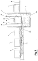
- the plant comprises a plurality of conveyor channels 6 arranged parallel to each other and full of water; the conveyor channels 6, by means of movement of the water contained in them, transport the fruit 9 to a collection zone 2 arranged at one end of the said conveyor channels 6.
- a water well 4 is envisaged, behind the collection zone and arranged perpendicularly to the conveyor channels 6.
- a loading conveyor 7 which transports empty bins 1: the loading conveyor 7 reaches the water well 4 at a loading zone 5 of the empty bins 1.
- a bin unloading conveyor 8 is envisaged; the loading zone 5 thus functions as a loading zone for empty bins and an unloading zone for full bins.
- the loading and unloading planes of the loading conveyor 7 and the unloading conveyor 8 are located at a higher level than the free surface level of the water.
- Raising means are envisaged in the loading and unloading zone 5, which means comprise a frame 16, arranged parallel to the free surface of the water, which frame 16 is raised and lowered by means of hydraulic jacks; during the empty bin loading phase and the full bin unloading phase, which phase is performed by means of pushing means of known type, the loading plane of the frame 16 is arranged at the same level as the loading planes of the loading conveyor 7 and the unloading conveyor 8.
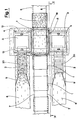
- the plant comprises at least one bell 3 arranged over the water well 4 with its axis perpendicular to the water well 4 itself and which can be moved axially, along a system of vertical guides 15 in which a plurality of sliding elements solid to the bell 3 are constrained to move, in such a way that the open end of the said bell 3 is brought, according to the various operative phases of the plant, which will be more fully described below, above or below the free surface lever of the water; the bell 3 is substantially perpendicular prism-shaped and exhibits a base that, for reasons that will better emerge hereinunder, is superimposable on the base of the bins 1.
- Transport means are also envisaged, usually constituted by bucket conveyors 20 and in any case by known type converyors, which take the fruit from the collection zone and insert it, by immersing it in the water, under the bell 3 when the bell 3 open end is below the free surface of the water.
- Aspirating means which comprise a pump 10, are positioned on the bell 3, which aspirating means on command aspirate the air from the inside of the bell 3.
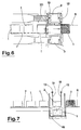
- the bell 3 can be moved along the water well 4 so as to be positioned, on command, at a collection zone or at an unloading zone; in order to allow such movement the vertical guide system which supports the bell 3 is anchored to horizontal guides 12 arranged above the water well 4.
- the plant of the invention is completely automatized and is equipped with command means, of electronic type and in any case of known type, which allow the plant itself to function according to successive operative phases which will be described below.
- the operation starts from a situation in which a bell 3 is in proximity to a collection zone, with its free end slightly below the free surface level of the water and where a bin 1 is sunk below the water surface level in the unloading zone; the frame 16 of the lifting means is obviously below the bin 1. Also obviously, empty bins 1 are positioned on the loading conveyor 7.
- the transport means begin to collect fruit from the collection zone and to bring them to a position below the bell 3; contemporaneously the pump 10 begins to aspirate air from the inside of the bell 3. Following the depression which is created internally to the bell 3, the water level inside the bell 3 rises with respect to the free surface level; therefore also the fruit, which is floating on the water, rises internally to the bell 3. It is thus possible to obtain quite a thick layer of fruit without having to immerse the open end of the bell 3 to a great depth below the surface of the water; the immersion of the free end of the bell 3 under the said free water surface serves only to create a seal against the outside; the immersion could thus be restricted to only a very limited depth.
- the bell 3 itself is moved along the horizontal guides 12 up until it arrives in the loading zone superior to the immersed bin 1.
- the bin 1 rises, meets the end of the bell 3 and pushes the bell 3 upwards, which bell 3 slides along its vertical guides 15; contemporaneously a breather pipe on the bell 3 is opened so as to allow air to enter into the bell 3 itself.
- the fruit contained in the bell 3 is deposited inside the bin 1.
- a further small lifting of the frame 16 is effected, as normally happens in known art plants, so as further to lift the bell 3 up until it reaches hooking means which make the bell 3 solid with the vertical guides 15, and which free the bell 3 from the bin 1; successively, an analogous movement of the bin 1 in a contrary direction is made so that it is brought back into the preceding position.
- the pushing means push an empty bin 1 on to the frame 16; the empty bin 1 causes the expulsion of the full bin 1 from the frame 16, which full bin 1 is then carried away from the plant.
Landscapes
- Engineering & Computer Science (AREA)
- Mechanical Engineering (AREA)
- Physics & Mathematics (AREA)
- Fluid Mechanics (AREA)
- Life Sciences & Earth Sciences (AREA)
- Agronomy & Crop Science (AREA)
- Filling Of Jars Or Cans And Processes For Cleaning And Sealing Jars (AREA)
- Basic Packing Technique (AREA)
- Sorting Of Articles (AREA)
- Apparatuses For Bulk Treatment Of Fruits And Vegetables And Apparatuses For Preparing Feeds (AREA)
- Packaging Of Special Articles (AREA)
- Packging For Living Organisms, Food Or Medicinal Products That Are Sensitive To Environmental Conditiond (AREA)
Claims (2)
- Unterwasseranlage zum Befüllen von Behältern, zum Befüllen von Obst, wie etwa von Äpfeln oder von ähnlichem Obst, enthaltend:mehrere Transportwannen (6) zur Beförderung des Obstes in einen oder mehrere Entnahmebereiche (2);ein Wasserschacht (4), der sich senkrecht zu den oben genannten Transportwannen (6) in Höhe der verschiedenen Entnahmebereiche (2) befindet;wenigstens ein sich im Wasserschacht (4) befindenden Bereich (5) zur Beschickung der leeren Behälter (1) sowie zum Entladen der vollen Behälter (1), wobei neben dem Bereich (5) sich ein Förderband zur Beschickung (7) und ein Förderband zur Abladung (8) der jeweils leeren oder vollen Behälter befinden, deren Ebenen der Beschickung und der Entladung überhalb des Wasserspiegels liegen;Hebemittel, die in den vorgenannten Beschickungs- und Entladungsbereichen montiert sind und der Versetzung des Behälters (1) von der Position überhalb des Wasserspiegels in eine Position unterhalb des Wasserspiegels dienen;dadurch gekennzeichnet daß:- Schubmittel, die zur Verschiebung der Behälter (1) in eine Position überhalb der vorgenannten Hebegeräte dienen;- wenigstens eine Vakuumglocke (3), die überhalb des Wasserschachtes (4) mit der Achse senkrecht zum Wasserspiegel montiert ist und sich axial bewegen kann, so daß sich die offene Seite der Vakuumglocke je nach der verschiedenen Arbeitsphase der Anlage entweder unter- oder überhalb des Wasserspiegels des Wasserschachtes (4) befindet, wobei die Vakuumglocke (3) sich des weiteren dem Wasserschacht (4) entlang bewegen und über eine entsprechende Steuerung nach Bedarf in eine der Entnahmebereiche (2) oder der Beschickungsbereichen (5) gebracht werden kann;- Transportmittel konventioneller Art zur Entnahme des Obstes vom Entnahmebereich (2) zwecks Einfüllung unterhalb der Vakuumglocke (3), wenn sich die offene Seite der Vakuumglocke (3) unterhalb des Wasserspiegels des Wasserschachtes (4) befindet,- die Vakuumglocke (3) so geformt ist, daß während der Versetzungsbewegung der Vakuumglocke (3) längs des Wasserschachtes (4), wenn sich die offene Seite der Vakuumglocke (3) leicht unterhalb des Wasserspiegels des Wasserschachtes (4) befindet, eine Dichtigkeit nach außen gebildet werden kann;- zur Anlage des weiteren Ansaugvorrichtungen (10) gehören, mit denen über eine entsprechende Steuerung Luft aus dem Inneren der Vakuumglocke (3) abgesaugt und somit während der Versetzungsbewegung der Vakuumglocke (3) längs des Wasserschachtes (4) ein Unterdruck im Inneren der Vakuumglocke (3) gebildet werden kann.
- Verfahren zur Benutzung der Anlage gemäss Anspruch 1, dadurch gekennzeichnet , daß diese Anlage die nachstehend beschriebenen Arbeitszyklen ausführen kann: Positionieren der leeren Behälter auf die überhalb des Wasserspiegels installierten Hebemittel bei gleichzeitiger Versetzung der Vakuumglocke (3), wenn deren offene Seite sich leicht unterhalb des Wasserspiegels in Höhe einer der Entnahmebereiche (2) befindet; vollständiges Eintauchen des Behälters (1) bei gleichzeitiger Einfüllung des Obstes in die Vakuumglocke (3), aus der während der Phase der Einfüllung Luft abgesaugt wird, so daß eine Aufnahme der gewünschten Obstmenge ermöglicht wird; Versetzung der Vakuumglocke (3) in die Bereiche zur Beschickung und Entladung, wobei die Ansaugung der Luft während der Versetzungsbewegung der Vakuumglocke (3) beibehalten wird; Anhebung des eingetauchten Behälters (1) mit der darüber befindlichen Vakuumglocke (3), bei gleichzeitiger Lufteinführung in die Vakuumglocke (3), so daß der Behälter (1) überhalb des Wasserspiegels positioniert werden kann; Verschiebung des leeren Behälters (1) auf die Hebemittel und anschließende Entleerung des vollen Behälters auf das Förderband zur Abladung (8) bei gleichzeitiger Versetzung der Vakuumglocke (3) zum Entnahmebereich.
Priority Applications (5)
| Application Number | Priority Date | Filing Date | Title |
|---|---|---|---|
| ES92830614T ES2106164T3 (es) | 1992-11-06 | 1992-11-06 | Una planta de llenado sub-acuatico de cajas. |
| DE69220670T DE69220670T2 (de) | 1992-11-06 | 1992-11-06 | Unterwasseranlage zum Befüllen von Behältern |
| EP92830614A EP0596183B1 (de) | 1992-11-06 | 1992-11-06 | Unterwasseranlage zum Befüllen von Behältern |
| AT92830614T ATE154915T1 (de) | 1992-11-06 | 1992-11-06 | Unterwasseranlage zum befüllen von behältern |
| US07/973,413 US5242250A (en) | 1992-11-06 | 1992-11-09 | Underwater bin-filling plant |
Applications Claiming Priority (2)
| Application Number | Priority Date | Filing Date | Title |
|---|---|---|---|
| EP92830614A EP0596183B1 (de) | 1992-11-06 | 1992-11-06 | Unterwasseranlage zum Befüllen von Behältern |
| US07/973,413 US5242250A (en) | 1992-11-06 | 1992-11-09 | Underwater bin-filling plant |
Publications (2)
| Publication Number | Publication Date |
|---|---|
| EP0596183A1 EP0596183A1 (de) | 1994-05-11 |
| EP0596183B1 true EP0596183B1 (de) | 1997-07-02 |
Family
ID=26132585
Family Applications (1)
| Application Number | Title | Priority Date | Filing Date |
|---|---|---|---|
| EP92830614A Expired - Lifetime EP0596183B1 (de) | 1992-11-06 | 1992-11-06 | Unterwasseranlage zum Befüllen von Behältern |
Country Status (5)
| Country | Link |
|---|---|
| US (1) | US5242250A (de) |
| EP (1) | EP0596183B1 (de) |
| AT (1) | ATE154915T1 (de) |
| DE (1) | DE69220670T2 (de) |
| ES (1) | ES2106164T3 (de) |
Families Citing this family (18)
| Publication number | Priority date | Publication date | Assignee | Title |
|---|---|---|---|---|
| GB2290517A (en) * | 1994-06-21 | 1996-01-03 | John Roland Breach | Packing buoyant articles |
| NL9500413A (nl) * | 1995-03-02 | 1996-10-01 | Greefs Wagen Carrosserie | Werkwijze en inrichting voor het behandelen van produkten van land- of tuinbouw. |
| FR2755883B1 (fr) * | 1996-11-19 | 1999-02-12 | Xeda International | Installation de tri de produits a canaux emplis d'eau |
| NL1012528C2 (nl) * | 1999-07-06 | 2001-01-15 | Burg S Machf B V | Inrichting voor het laden van vruchten. |
| FR2808788B1 (fr) * | 2000-05-09 | 2002-09-27 | Pescia Antonio Crovara | Manche d'immersion forcee d'un article |
| FR2808706B1 (fr) * | 2000-05-09 | 2003-08-08 | Pescia Antonio Crovara | Installation de tri d'articles flottants tels que des fruits |
| FR2835507B1 (fr) * | 2002-02-01 | 2004-07-02 | Caustier France | Dispositif de remplissage hydraulique de caisses avec des objets flottants comportant un portique muni de moyens de prehension et de deplacements vertical et horizontal d'une dite caisse |
| FR2868042B1 (fr) * | 2004-03-23 | 2006-06-02 | Materiel Arboriculture | Installation de remplissage hydraulique de caisses par des objets flottants tels que des fruits a pompe mixte unique |
| NL2005127C2 (nl) * | 2010-02-23 | 2011-08-24 | Greefs Wagen Carrosserie | Buffersysteem voor vruchten zoals appels. |
| US8821078B2 (en) * | 2011-01-07 | 2014-09-02 | Conagra Foods Lamb Weston, Inc. | Fluid-based article distribution and sorting system |
| NL2011366C2 (nl) * | 2013-09-02 | 2015-03-03 | Greefs Wagen Carrosserie | Vulinrichting en werkwijze voor het met een in een waterige vloeistof drijvende en/of zwevende producten vullen van een houder. |
| US10138011B2 (en) * | 2013-09-02 | 2018-11-27 | De Greef's Wagen-, Carrosserie-En Machinebouw B.V. | Filling device and method for filling a container with products floating and/or suspended in an aqueous liquid |
| US11483975B2 (en) | 2013-12-20 | 2022-11-01 | Harvest Croo, Llc | Harvester pick deck suspension |
| PL2910481T3 (pl) * | 2014-02-24 | 2016-07-29 | Ltw Intralogistics Gmbh | Sposób częściowego rozładunku pływalnych przedmiotów oraz urządzenie do realizacji tego sposobu |
| WO2016028163A1 (en) * | 2014-08-19 | 2016-02-25 | Compac Technologies Limited | A singulation apparatus |
| FR3049269B1 (fr) | 2016-03-25 | 2020-01-03 | Maf Agrobotic | Procede et dispositif de remplissage hydraulique de caisses par des objets flottants a alimentation forcee |
| US11198529B2 (en) * | 2019-04-01 | 2021-12-14 | Harvest Croo, Llc | Apparatus and method for filling a container with fragile fruit |
| CN117963530B (zh) * | 2024-03-28 | 2024-07-02 | 斯美科智能制造(杭州)有限公司 | 一种水下输送装置 |
Family Cites Families (3)
| Publication number | Priority date | Publication date | Assignee | Title |
|---|---|---|---|---|
| US3097460A (en) * | 1961-02-06 | 1963-07-16 | Univ California | Bulk bin filler |
| NL164819C (nl) * | 1975-12-19 | 1981-02-16 | Greefa Machinebouw B V | Kistenvulinrichting. |
| US4051645A (en) * | 1976-10-26 | 1977-10-04 | Aaron James Warkentin | Comestible packaging apparatus |
-
1992
- 1992-11-06 EP EP92830614A patent/EP0596183B1/de not_active Expired - Lifetime
- 1992-11-06 ES ES92830614T patent/ES2106164T3/es not_active Expired - Lifetime
- 1992-11-06 DE DE69220670T patent/DE69220670T2/de not_active Expired - Fee Related
- 1992-11-06 AT AT92830614T patent/ATE154915T1/de not_active IP Right Cessation
- 1992-11-09 US US07/973,413 patent/US5242250A/en not_active Expired - Fee Related
Also Published As
| Publication number | Publication date |
|---|---|
| US5242250A (en) | 1993-09-07 |
| DE69220670D1 (de) | 1997-08-07 |
| ATE154915T1 (de) | 1997-07-15 |
| EP0596183A1 (de) | 1994-05-11 |
| DE69220670T2 (de) | 1998-02-12 |
| ES2106164T3 (es) | 1997-11-01 |
Similar Documents
| Publication | Publication Date | Title |
|---|---|---|
| US5242250A (en) | Underwater bin-filling plant | |
| KR100375977B1 (ko) | 웨이퍼 처리 장치 | |
| US4365591A (en) | Livestock handling system and apparatus therefor | |
| US4541762A (en) | Apparatus for loading and/or unloading machine tools or the like | |
| EP4242124A2 (de) | Lagerbehälter für automatisiertes regalbediensystem | |
| US6503044B1 (en) | Method for emptying parcel containers | |
| CA2290082A1 (en) | Receiving device and receiving means, transfer device, and workstation and method for their operation | |
| US6283703B1 (en) | Automatic conveying apparatus for JEDEC carrier members | |
| US5280694A (en) | Apparatus and method for stacking small goods | |
| US20250058361A1 (en) | Automated system for vertical sorting of articles and method | |
| KR0141351B1 (ko) | 트레이의 운반 방법 및 장치 | |
| US4051645A (en) | Comestible packaging apparatus | |
| CN218797404U (zh) | 一种香菇分拣系统 | |
| CN109071049A (zh) | 以强迫供应的方式由漂浮物体液压填充箱体的方法和装置 | |
| CN112707074B (zh) | 堆垛存放组件 | |
| US4642014A (en) | Framing system | |
| CN111409983B (zh) | 一种取货装置及取货方法 | |
| CN117565206A (zh) | 一种料罐自动转运设备 | |
| CN210823037U (zh) | 一种磁保持继电器的下料装箱设备 | |
| US4316682A (en) | Ore carrier | |
| CN114514894A (zh) | 用于将家禽放置到家禽传送带的设备 | |
| US5016860A (en) | "No-nick" part-handling apparatus and method | |
| RU2833263C2 (ru) | Автоматизированная установка комплектования заказов | |
| CN223213171U (zh) | 一种双层输送线 | |
| AU2021232638B2 (en) | Storage system having two transfer positions oriented obliquely to each other |
Legal Events
| Date | Code | Title | Description |
|---|---|---|---|
| PUAI | Public reference made under article 153(3) epc to a published international application that has entered the european phase |
Free format text: ORIGINAL CODE: 0009012 |
|
| AK | Designated contracting states |
Kind code of ref document: A1 Designated state(s): AT BE CH DE ES FR GB GR LI LU NL PT |
|
| 17P | Request for examination filed |
Effective date: 19940915 |
|
| 17Q | First examination report despatched |
Effective date: 19951109 |
|
| GRAG | Despatch of communication of intention to grant |
Free format text: ORIGINAL CODE: EPIDOS AGRA |
|
| GRAH | Despatch of communication of intention to grant a patent |
Free format text: ORIGINAL CODE: EPIDOS IGRA |
|
| GRAH | Despatch of communication of intention to grant a patent |
Free format text: ORIGINAL CODE: EPIDOS IGRA |
|
| GRAA | (expected) grant |
Free format text: ORIGINAL CODE: 0009210 |
|
| AK | Designated contracting states |
Kind code of ref document: B1 Designated state(s): AT BE CH DE ES FR GB GR LI LU NL PT |
|
| PG25 | Lapsed in a contracting state [announced via postgrant information from national office to epo] |
Ref country code: LI Effective date: 19970702 Ref country code: GR Free format text: LAPSE BECAUSE OF FAILURE TO SUBMIT A TRANSLATION OF THE DESCRIPTION OR TO PAY THE FEE WITHIN THE PRESCRIBED TIME-LIMIT Effective date: 19970702 Ref country code: CH Effective date: 19970702 Ref country code: AT Effective date: 19970702 |
|
| REF | Corresponds to: |
Ref document number: 154915 Country of ref document: AT Date of ref document: 19970715 Kind code of ref document: T |
|
| REG | Reference to a national code |
Ref country code: CH Ref legal event code: EP |
|
| REF | Corresponds to: |
Ref document number: 69220670 Country of ref document: DE Date of ref document: 19970807 |
|
| PG25 | Lapsed in a contracting state [announced via postgrant information from national office to epo] |
Ref country code: PT Effective date: 19971002 |
|
| ET | Fr: translation filed | ||
| REG | Reference to a national code |
Ref country code: ES Ref legal event code: FG2A Ref document number: 2106164 Country of ref document: ES Kind code of ref document: T3 |
|
| PG25 | Lapsed in a contracting state [announced via postgrant information from national office to epo] |
Ref country code: LU Free format text: LAPSE BECAUSE OF NON-PAYMENT OF DUE FEES Effective date: 19971106 Ref country code: GB Free format text: LAPSE BECAUSE OF NON-PAYMENT OF DUE FEES Effective date: 19971106 |
|
| REG | Reference to a national code |
Ref country code: CH Ref legal event code: PL |
|
| PLBE | No opposition filed within time limit |
Free format text: ORIGINAL CODE: 0009261 |
|
| 26N | No opposition filed | ||
| GBPC | Gb: european patent ceased through non-payment of renewal fee |
Effective date: 19971106 |
|
| PGFP | Annual fee paid to national office [announced via postgrant information from national office to epo] |
Ref country code: FR Payment date: 19990430 Year of fee payment: 7 Ref country code: ES Payment date: 19990430 Year of fee payment: 7 Ref country code: DE Payment date: 19990430 Year of fee payment: 7 |
|
| PGFP | Annual fee paid to national office [announced via postgrant information from national office to epo] |
Ref country code: BE Payment date: 19990517 Year of fee payment: 7 |
|
| PGFP | Annual fee paid to national office [announced via postgrant information from national office to epo] |
Ref country code: NL Payment date: 19990526 Year of fee payment: 7 |
|
| PG25 | Lapsed in a contracting state [announced via postgrant information from national office to epo] |
Ref country code: ES Free format text: LAPSE BECAUSE OF NON-PAYMENT OF DUE FEES Effective date: 19991107 |
|
| PG25 | Lapsed in a contracting state [announced via postgrant information from national office to epo] |
Ref country code: BE Free format text: LAPSE BECAUSE OF NON-PAYMENT OF DUE FEES Effective date: 19991130 |
|
| BERE | Be: lapsed |
Owner name: COMPAGNONI FELICE Effective date: 19991130 |
|
| PG25 | Lapsed in a contracting state [announced via postgrant information from national office to epo] |
Ref country code: NL Free format text: LAPSE BECAUSE OF NON-PAYMENT OF DUE FEES Effective date: 20000601 |
|
| PG25 | Lapsed in a contracting state [announced via postgrant information from national office to epo] |
Ref country code: FR Free format text: LAPSE BECAUSE OF NON-PAYMENT OF DUE FEES Effective date: 20000731 |
|
| NLV4 | Nl: lapsed or anulled due to non-payment of the annual fee |
Effective date: 20000601 |
|
| PG25 | Lapsed in a contracting state [announced via postgrant information from national office to epo] |
Ref country code: DE Free format text: LAPSE BECAUSE OF NON-PAYMENT OF DUE FEES Effective date: 20000901 |
|
| REG | Reference to a national code |
Ref country code: FR Ref legal event code: ST |
|
| REG | Reference to a national code |
Ref country code: ES Ref legal event code: FD2A Effective date: 20001214 |