EP0596233A2 - Dispositif de détection de signaux haute tension - Google Patents
Dispositif de détection de signaux haute tension Download PDFInfo
- Publication number
- EP0596233A2 EP0596233A2 EP93115300A EP93115300A EP0596233A2 EP 0596233 A2 EP0596233 A2 EP 0596233A2 EP 93115300 A EP93115300 A EP 93115300A EP 93115300 A EP93115300 A EP 93115300A EP 0596233 A2 EP0596233 A2 EP 0596233A2
- Authority
- EP
- European Patent Office
- Prior art keywords
- ignition coil
- ignition
- high voltage
- diode
- voltage
- Prior art date
- Legal status (The legal status is an assumption and is not a legal conclusion. Google has not performed a legal analysis and makes no representation as to the accuracy of the status listed.)
- Granted
Links
Images
Classifications
-
- H—ELECTRICITY
- H01—ELECTRIC ELEMENTS
- H01T—SPARK GAPS; OVERVOLTAGE ARRESTERS USING SPARK GAPS; SPARKING PLUGS; CORONA DEVICES; GENERATING IONS TO BE INTRODUCED INTO NON-ENCLOSED GASES
- H01T13/00—Sparking plugs
- H01T13/58—Testing
-
- F—MECHANICAL ENGINEERING; LIGHTING; HEATING; WEAPONS; BLASTING
- F02—COMBUSTION ENGINES; HOT-GAS OR COMBUSTION-PRODUCT ENGINE PLANTS
- F02P—IGNITION, OTHER THAN COMPRESSION IGNITION, FOR INTERNAL-COMBUSTION ENGINES; TESTING OF IGNITION TIMING IN COMPRESSION-IGNITION ENGINES
- F02P17/00—Testing of ignition installations, e.g. in combination with adjusting; Testing of ignition timing in compression-ignition engines
- F02P17/12—Testing characteristics of the spark, ignition voltage or current
-
- G—PHYSICS
- G01—MEASURING; TESTING
- G01R—MEASURING ELECTRIC VARIABLES; MEASURING MAGNETIC VARIABLES
- G01R15/00—Details of measuring arrangements of the types provided for in groups G01R17/00 - G01R29/00, G01R33/00 - G01R33/26 or G01R35/00
- G01R15/14—Adaptations providing voltage or current isolation, e.g. for high-voltage or high-current networks
- G01R15/16—Adaptations providing voltage or current isolation, e.g. for high-voltage or high-current networks using capacitive devices
-
- F—MECHANICAL ENGINEERING; LIGHTING; HEATING; WEAPONS; BLASTING
- F02—COMBUSTION ENGINES; HOT-GAS OR COMBUSTION-PRODUCT ENGINE PLANTS
- F02P—IGNITION, OTHER THAN COMPRESSION IGNITION, FOR INTERNAL-COMBUSTION ENGINES; TESTING OF IGNITION TIMING IN COMPRESSION-IGNITION ENGINES
- F02P17/00—Testing of ignition installations, e.g. in combination with adjusting; Testing of ignition timing in compression-ignition engines
- F02P2017/006—Testing of ignition installations, e.g. in combination with adjusting; Testing of ignition timing in compression-ignition engines using a capacitive sensor
Definitions
- the invention relates to a device for detecting high-voltage signals according to the preamble of the main claim.
- a generic device is known in which the secondary high voltage occurring at an ignition coil is detected with a capacitive coupling.
- the ignition coil is part of an ignition system which is intended for the ignition of spark-ignition internal combustion engines.
- the ignition coil contains an integrated diode, which is arranged in the secondary circuit of the ignition coil.
- the diode has the effect that the high voltage occurring at a spark plug can only ever have a predetermined polarity. This measure prevents unwanted ignition sparks that could occur during the transition to a closing phase of the ignition system.
- the capacitive coupling directly detects the high voltage present on the secondary winding of the ignition coil. In the outer area of the ignition coil body, a measuring point is fixed at which a signal pickup is to be attached.
- the invention has for its object to enable the most complete possible diagnosis of high-voltage signals on an ignition coil containing an integrated diode.
- the device according to the invention for detecting high-voltage signals has the advantage that faults in the ignition circuit, for example impermissibly high shunts or even short-circuits, and defects in the integrated diode can be identified.
- a comparison of the signals occurring before and after the diode enables a statement about the state of the diode.
- the plug-on part is provided with an electrically insulating surface. Advantages of this measure result in particular from ignition systems whose ignition coils are mounted directly near the spark plugs. Short circuits against nearby engine parts are avoided.
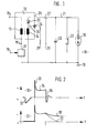
- FIG. 1 shows a block diagram of a device according to the invention for detecting high-voltage signals
- FIG. 2 shows two signal curves as a function of the time that occur in the device shown in FIG. 1.
- FIG. 1 shows an ignition system 10 which is provided for generating sparks on a spark plug 11.
- the ignition system 10 contains an ignition coil 12 which has at least one primary winding 13 and at least one secondary winding 14.
- a first connection 15 of the primary winding 13 can be connected to an energy source, not shown.
- a second connection 16 of the primary winding 13 can be connected to a ground 18 via switching means 17.
- the switching means 17 can be actuated via a control input 19.
- the secondary winding 14 is connected on the one hand to ground 18 and on the other hand to a cathode connection of a diode 20.
- An anode connection of the diode 20 is connected to a high-voltage line 21, which leads to the spark plug 11.
- a capacitor 22 and a resistor 23 are entered between the high-voltage line 21 and the ground 18.
- the capacitor 22 and the resistor 23 are not present as components.
- the capacitor 22 symbolizes the inevitable capacitance between the high-voltage line 21 and the ground 18 and the resistor 23 symbolizes a shunt occurring between the high-voltage line 21 and the ground 18.
- a first capacitive coupling 24 is arranged on the ignition coil 12 and is provided at a defined location on a housing 25 of the ignition coil 12.
- the first capacitive coupling 24 detects the high voltage occurring on the secondary winding 14 before the diode 20. If the connection between the secondary winding 14 and the diode 20 is not directly on the housing 25, the first capacitive coupling 24 can be guided to the desired location with an extension part 26 located within the housing 25 of the ignition coil 12.
- a second capacitive signal coupling 27 is provided for detecting the high-voltage signals occurring on the high-voltage line 21.
- the first capacitive coupling 24 leads to a connection 28 and the second capacitive coupling 27 leads to a connection 29.
- the connections 28, 29 can be connected to a diagnostic device (not shown in more detail).
- Figure 2 shows two waveforms 30, 31 depending on the time t.
- the first signal curve 30 shown in FIG. 2 shows the secondary high voltage which is coupled out by the first capacitive signal coupling 24 and which occurs on the secondary winding 14 of the ignition coil 12.
- the second signal curve 31 shown in the lower part of FIG. 2 shows the high voltage on the high voltage line 21 that can be detected with the second capacitive signal coupling 27.
- the first signal curve 30 begins with a voltage jump 32, which occurs at the beginning of a closing phase of the switching means 17.
- the closing phase is initiated with a corresponding signal at the control input 19 of the switching means 17.
- a potential at the second connection 16 of the primary winding 13 which corresponds to the potential occurring at the first connection 15.
- the connection of the second connection 16 to ground 18 at the beginning of the closing process results in a potential jump at the second connection 16, which is transmitted to the secondary side and occurs there as a voltage jump 32.
- the polarity of the voltage jump 32 depends on the circuit arrangement. It is essential that the voltage jump 32 is directed in the opposite direction to the subsequent firing needle 33, which occurs after the closing phase has ended.
- the peak voltage value of the ignition needle 33 corresponds to the breakdown voltage for the ignition spark at the spark plug 11.
- the ignition needle 33 is followed by a burning voltage line 34, which ends with a spark break at time T. After the time T, a decay process 35 takes place, the course of which is mainly determined by the inductance of the secondary winding 14 and the capacitance of the capacitor 22.
- the second signal curve 31 shown in the lower part of FIG. 2 initially differs from the first signal curve 30 shown in the upper part of FIG. 2 in that in particular the voltage jump 32 contained in the first signal curve 30, which is dependent on those present on the spark plug 11, is omitted Conditions could be sufficient to generate an ignition spark. If the spark plug 11 is provided to ignite a spark-ignition internal combustion engine, such a so-called closing spark must be avoided under all circumstances, since it would occur during the compression phase.
- the ignition needle and the line voltage in the second signal curve 31 coincide with the first signal curve 30 except for the forward voltage of the diode 20 and a zero-point shift possibly caused by the capacitive coupling.
- a diagnosis on the ignition system 10 is already possible with the evaluation of one of the two signal profiles 30, 31.
- the evaluation and comparison of the two signal profiles 30, 31 significantly increases the diagnostic options.
- a comparison of the two signal curves 30, 31 allows conclusions to be drawn about the state of the diode 20.
- the evaluation of the decay process 36, 37 enables an evaluation of a shunt in the ignition circuit.
- the first decay process 36 corresponds to a good high-resistance shunt, which is symbolized by the resistor 23, while the second decay process 37 corresponds to a poor low-resistance shunt.
- the two capacitive couplings 24, 27 are each advantageously implemented with a plug-on part.
- the first plug-in part for the first capacitive coupling 24 is to be fastened to an attachment location which is preferably already marked during the manufacture of the ignition coil 12.
- the other plug-in part of the second capacitive coupling 27 can also be attached directly to the housing 25 of the ignition coil 12 or to the high-voltage line 21 at a suitable location.
- More recent concepts of ignition systems 10 provide, instead of a longer high-voltage line 21, only short connecting pieces, which are guided in insulating parts, between an attachable ignition coil 12 and the spark plug 10. This results in partially cramped installation conditions, which make it difficult to attach at least the second capacitive coupling 27.
- the plug-in part for the second capacitive coupling 27 is coated with an electrically insulating surface which prevents the occurrence of short circuits to ground 18. Furthermore, it has proven to be expedient to electrically isolate the line leading from the second capacitive coupling 27 to the connection 29. This measure essentially also prevents a possible short circuit to ground 18.
- the device according to the invention is equally suitable for diagnosing two-spark ignition systems in which both connections of the Se secondary winding 14 of the ignition coil 12 are connected to spark plugs.
Landscapes
- Engineering & Computer Science (AREA)
- Chemical & Material Sciences (AREA)
- Combustion & Propulsion (AREA)
- Physics & Mathematics (AREA)
- General Physics & Mathematics (AREA)
- Mechanical Engineering (AREA)
- General Engineering & Computer Science (AREA)
- Ignition Installations For Internal Combustion Engines (AREA)
Applications Claiming Priority (2)
| Application Number | Priority Date | Filing Date | Title |
|---|---|---|---|
| DE4236878A DE4236878A1 (de) | 1992-10-31 | 1992-10-31 | Vorrichtung zum Erfassen von Hochspannungssignalen |
| DE4236878 | 1992-10-31 |
Publications (3)
| Publication Number | Publication Date |
|---|---|
| EP0596233A2 true EP0596233A2 (fr) | 1994-05-11 |
| EP0596233A3 EP0596233A3 (fr) | 1995-02-15 |
| EP0596233B1 EP0596233B1 (fr) | 1997-01-15 |
Family
ID=6471851
Family Applications (1)
| Application Number | Title | Priority Date | Filing Date |
|---|---|---|---|
| EP93115300A Expired - Lifetime EP0596233B1 (fr) | 1992-10-31 | 1993-09-23 | Dispositif de détection de signaux haute tension |
Country Status (3)
| Country | Link |
|---|---|
| EP (1) | EP0596233B1 (fr) |
| DE (2) | DE4236878A1 (fr) |
| ES (1) | ES2096826T3 (fr) |
Cited By (3)
| Publication number | Priority date | Publication date | Assignee | Title |
|---|---|---|---|---|
| EP0716227A3 (fr) * | 1994-12-06 | 1997-11-26 | Robert Bosch Gmbh | Dispositif de saisie de signal d'allumage |
| RU2123132C1 (ru) * | 1996-11-10 | 1998-12-10 | Акционерное общество "АвтоВАЗ" | Катушка зажигания |
| RU2152534C1 (ru) * | 1998-04-13 | 2000-07-10 | Акционерное общество "АвтоВАЗ" | Катушка зажигания |
Families Citing this family (1)
| Publication number | Priority date | Publication date | Assignee | Title |
|---|---|---|---|---|
| DE10110047A1 (de) | 2001-03-02 | 2002-09-05 | Bosch Gmbh Robert | Vorrichtung zur Diagnose einer fremdgezündeten Brennkraftmaschine |
Family Cites Families (4)
| Publication number | Priority date | Publication date | Assignee | Title |
|---|---|---|---|---|
| DE4028554C2 (de) * | 1990-09-08 | 2000-02-17 | Bosch Gmbh Robert | Zündanlage einer Brennkraftmaschine mit einer Anordnung zur sekundärseitigen Zündsignalauskopplung |
| US5215067A (en) * | 1991-03-07 | 1993-06-01 | Honda Giken Kogyo Kabushiki Kaisha | Misfire-detecting system for internal combustion engines |
| EP0508804B1 (fr) * | 1991-04-12 | 1997-12-29 | Ngk Spark Plug Co., Ltd | Dispositif pour la détection d'une forme de tension secondaire pour un moteur à combustion interne |
| US5365910A (en) * | 1991-05-14 | 1994-11-22 | Ngk Spark Plug Co., Ltd. | Misfire detector for use in internal combustion engine |
-
1992
- 1992-10-31 DE DE4236878A patent/DE4236878A1/de not_active Withdrawn
-
1993
- 1993-09-23 EP EP93115300A patent/EP0596233B1/fr not_active Expired - Lifetime
- 1993-09-23 ES ES93115300T patent/ES2096826T3/es not_active Expired - Lifetime
- 1993-09-23 DE DE59305135T patent/DE59305135D1/de not_active Expired - Lifetime
Cited By (3)
| Publication number | Priority date | Publication date | Assignee | Title |
|---|---|---|---|---|
| EP0716227A3 (fr) * | 1994-12-06 | 1997-11-26 | Robert Bosch Gmbh | Dispositif de saisie de signal d'allumage |
| RU2123132C1 (ru) * | 1996-11-10 | 1998-12-10 | Акционерное общество "АвтоВАЗ" | Катушка зажигания |
| RU2152534C1 (ru) * | 1998-04-13 | 2000-07-10 | Акционерное общество "АвтоВАЗ" | Катушка зажигания |
Also Published As
| Publication number | Publication date |
|---|---|
| ES2096826T3 (es) | 1997-03-16 |
| DE59305135D1 (de) | 1997-02-27 |
| EP0596233A3 (fr) | 1995-02-15 |
| DE4236878A1 (de) | 1994-05-05 |
| EP0596233B1 (fr) | 1997-01-15 |
Similar Documents
| Publication | Publication Date | Title |
|---|---|---|
| DE10012854B4 (de) | Verbrennungszustands-Detektionsgerät für Verbrennungsmotor | |
| DE19953710B4 (de) | Verfahren und Vorrichtung zur Meßfenster-Positionierung für die Ionenstrommessung | |
| DE19514633A1 (de) | Vorrichtung zur Erfassung von Fehlzündungen in einer Brennkraftmaschine | |
| DE69331790T2 (de) | Fehlzündungsdetektor mit verschiedenen Methoden bei hoher und niedriger Motorgeschwindigkeit | |
| EP0561807B1 (fr) | Dispositif pour l'acquisition de signaux | |
| DE69412039T2 (de) | Verfahren und Vorrichtung einer Spulenzündung mit zusätzlichen Entladungen zur Diagnose | |
| DE4239803C2 (de) | Ionisationsstromdetektoreinrichtung für eine Brennkraftmaschine | |
| EP0596233B1 (fr) | Dispositif de détection de signaux haute tension | |
| EP0455649B1 (fr) | Procede d'attribution de signaux d'allumage a un cylindre de reference | |
| DE3706786C1 (en) | Device for monitoring at least two electrical loads in motor vehicles | |
| DE4409749A1 (de) | Verfahren zur Erkennung klopfender Verbrennung bei einer Brennkraftmaschine mit einer Hochspannungstransistorspulenzündeinrichtung | |
| DE3417676C2 (fr) | ||
| DE2452469A1 (de) | Kompressionsdruckmessgeraet | |
| DE4018895C2 (de) | Diagnosevorrichtung | |
| EP0707144B1 (fr) | Dispositif de détection des signaux d'allumage | |
| DE3806649C2 (fr) | ||
| DE69727871T2 (de) | Verfahren zur Erkennung der Phasenlage eines Zylinders zur Zündung in einer Brennkraftmaschine | |
| DE2431799A1 (de) | Schaltung zur aufbereitung von gebersignalen, welche aus der zuendanlage eines ottomotors gewonnen werden | |
| EP0529281B1 (fr) | Procédé de détection d'une mise en contact des lignes de mesure | |
| EP0540878B1 (fr) | Dispositif pour l'évaluation d'impulsions d'allumage | |
| EP0705386B1 (fr) | Procede permettant de detecter un groupe d'impulsions d'allumage | |
| EP0615580B1 (fr) | Systeme d'allumage a limitation de la tension primaire et a diagnostic de defauts | |
| DE10031553A1 (de) | Induktive Zündvorrichtung mit Ionenstrommeßeinrichtung | |
| DE2532627A1 (de) | Schaltungsanordnung zur impulsformung und stoersignalunterdrueckung | |
| DE3734080A1 (de) | Transistorzuendvorrichtung fuer eine brennkraftmaschine |
Legal Events
| Date | Code | Title | Description |
|---|---|---|---|
| PUAI | Public reference made under article 153(3) epc to a published international application that has entered the european phase |
Free format text: ORIGINAL CODE: 0009012 |
|
| AK | Designated contracting states |
Kind code of ref document: A2 Designated state(s): DE ES FR GB IT |
|
| PUAL | Search report despatched |
Free format text: ORIGINAL CODE: 0009013 |
|
| AK | Designated contracting states |
Kind code of ref document: A3 Designated state(s): DE ES FR GB IT |
|
| 17P | Request for examination filed |
Effective date: 19950816 |
|
| 17Q | First examination report despatched |
Effective date: 19960214 |
|
| GRAG | Despatch of communication of intention to grant |
Free format text: ORIGINAL CODE: EPIDOS AGRA |
|
| GRAH | Despatch of communication of intention to grant a patent |
Free format text: ORIGINAL CODE: EPIDOS IGRA |
|
| GRAH | Despatch of communication of intention to grant a patent |
Free format text: ORIGINAL CODE: EPIDOS IGRA |
|
| GRAA | (expected) grant |
Free format text: ORIGINAL CODE: 0009210 |
|
| AK | Designated contracting states |
Kind code of ref document: B1 Designated state(s): DE ES FR GB IT |
|
| ET | Fr: translation filed | ||
| REF | Corresponds to: |
Ref document number: 59305135 Country of ref document: DE Date of ref document: 19970227 |
|
| REG | Reference to a national code |
Ref country code: ES Ref legal event code: FG2A Ref document number: 2096826 Country of ref document: ES Kind code of ref document: T3 |
|
| ITF | It: translation for a ep patent filed | ||
| GBT | Gb: translation of ep patent filed (gb section 77(6)(a)/1977) |
Effective date: 19970320 |
|
| PLBE | No opposition filed within time limit |
Free format text: ORIGINAL CODE: 0009261 |
|
| 26N | No opposition filed | ||
| REG | Reference to a national code |
Ref country code: GB Ref legal event code: IF02 |
|
| PGFP | Annual fee paid to national office [announced via postgrant information from national office to epo] |
Ref country code: FR Payment date: 20060922 Year of fee payment: 14 |
|
| PGFP | Annual fee paid to national office [announced via postgrant information from national office to epo] |
Ref country code: ES Payment date: 20060926 Year of fee payment: 14 |
|
| REG | Reference to a national code |
Ref country code: FR Ref legal event code: ST Effective date: 20080531 |
|
| PG25 | Lapsed in a contracting state [announced via postgrant information from national office to epo] |
Ref country code: FR Free format text: LAPSE BECAUSE OF NON-PAYMENT OF DUE FEES Effective date: 20071001 |
|
| REG | Reference to a national code |
Ref country code: ES Ref legal event code: FD2A Effective date: 20070924 |
|
| PG25 | Lapsed in a contracting state [announced via postgrant information from national office to epo] |
Ref country code: ES Free format text: LAPSE BECAUSE OF NON-PAYMENT OF DUE FEES Effective date: 20070924 |
|
| PGFP | Annual fee paid to national office [announced via postgrant information from national office to epo] |
Ref country code: IT Payment date: 20100925 Year of fee payment: 18 |
|
| PGFP | Annual fee paid to national office [announced via postgrant information from national office to epo] |
Ref country code: DE Payment date: 20101126 Year of fee payment: 18 |
|
| PGFP | Annual fee paid to national office [announced via postgrant information from national office to epo] |
Ref country code: GB Payment date: 20110923 Year of fee payment: 19 |
|
| GBPC | Gb: european patent ceased through non-payment of renewal fee |
Effective date: 20120923 |
|
| REG | Reference to a national code |
Ref country code: DE Ref legal event code: R119 Ref document number: 59305135 Country of ref document: DE Effective date: 20130403 |
|
| PG25 | Lapsed in a contracting state [announced via postgrant information from national office to epo] |
Ref country code: GB Free format text: LAPSE BECAUSE OF NON-PAYMENT OF DUE FEES Effective date: 20120923 Ref country code: DE Free format text: LAPSE BECAUSE OF NON-PAYMENT OF DUE FEES Effective date: 20130403 |
|
| PG25 | Lapsed in a contracting state [announced via postgrant information from national office to epo] |
Ref country code: IT Free format text: LAPSE BECAUSE OF NON-PAYMENT OF DUE FEES Effective date: 20120923 |