EP0596363B1 - Arrangement pour encercler un objet - Google Patents
Arrangement pour encercler un objet Download PDFInfo
- Publication number
- EP0596363B1 EP0596363B1 EP93117249A EP93117249A EP0596363B1 EP 0596363 B1 EP0596363 B1 EP 0596363B1 EP 93117249 A EP93117249 A EP 93117249A EP 93117249 A EP93117249 A EP 93117249A EP 0596363 B1 EP0596363 B1 EP 0596363B1
- Authority
- EP
- European Patent Office
- Prior art keywords
- guide
- strap
- tongue
- implement
- wrapping
- Prior art date
- Legal status (The legal status is an assumption and is not a legal conclusion. Google has not performed a legal analysis and makes no representation as to the accuracy of the status listed.)
- Expired - Lifetime
Links
Images


Classifications
-
- B—PERFORMING OPERATIONS; TRANSPORTING
- B65—CONVEYING; PACKING; STORING; HANDLING THIN OR FILAMENTARY MATERIAL
- B65B—MACHINES, APPARATUS OR DEVICES FOR, OR METHODS OF, PACKAGING ARTICLES OR MATERIALS; UNPACKING
- B65B13/00—Bundling articles
- B65B13/02—Applying and securing binding material around articles or groups of articles, e.g. using strings, wires, strips, bands or tapes
- B65B13/025—Hand-held tools
- B65B13/027—Hand-held tools for applying straps having preformed connecting means, e.g. cable ties
Definitions
- the invention relates to an e assembly for binding an article according to the preamble of claim 1 comprising a tape having a strap tongue and a connected to one end of the strap tongue s lock with a strap opening to receive the other end of which includes and an elongated tool, an openable and closable wrapping guide for guiding the tape is at its end face around the article and a buckle mounting from which the wrapping guide starts and to which it returns.
- the strap tongue lies in the loop guide and the lock in the lock holder.
- a guide channel which runs approximately parallel to the longitudinal direction of the tool, is provided for conveying the band from an initial position, which can be determined, for example, by a band magazine, into the binding position.
- the invention seeks to get closer to the scope of the largest possible circular cross-section to be accommodated in the looping guide with the lock holder and therefore has to solve the problem of how the leading end of the band tongue Introducing the tape into the binding position from a considerable distance from the lock holder can be performed so precisely that the start of the loop guide is met exactly.
- the solution lies in the features of claim 1; preferably further developments of the tool of the arrangement according to claim 1 are specified in the subclaims.
- the feature that the angle between the direction of the end of the band tongue connected to the lock and the direction of the band opening on the side facing the looping guide is between 135 and 180 degrees, corresponds to the feature on the tool that the end of the feed channel and the end of the Wrap the guide at an acute angle to each other, which results in the above-mentioned overlap of the guide path and the wrap when approaching the lock bracket.
- the guide device which gives the band tongue the required alignment from a greater distance from the lock holder, consists of a straight or concave guide surface, which can be formed by the wall of the guide channel, and a guide element which presses the band tongue against this guide surface. This guide element must be removable from the position in which the band is pressed against the guide surface, so that the lock of the band can pass through, as far as it corresponds to the dimensions of the lock.
- a bend should preferably be provided in the guide channel before its end . This is permitted by the high guide quality of the guide device and gives the possibility of feeding the band of the lock holder parallel to the end face in which it is attached , although for reasons of space it initially lies in a section of the guide channel running parallel to the longitudinal direction of the tool.
- the guide element can be moved by suitable drive means, which in turn are synchronized with the binding process are controlled.
- suitable drive means which in turn are synchronized with the binding process are controlled.
- the guide element is passively moved by the band passing through, in that the guide element is formed by a spring-loaded rocker which projects into the guide channel at an acute angle to the direction of advance of the band.
- the band tongue which runs into the acute angle between the rocker and the wall of the guide channel, pushes the rocker aside and is thereby pressed against the wall of the guide channel as a guide surface. This gives it a defined position and direction.
- the belt is pushed through the guide channel by means of a slide, which must therefore also pass between the rocker and the guide surface. So that the guide rocker does not block the return path of the slide, it is equipped according to the invention with a control surface lifting the guide element from the guide surface.
- a spur Seen from the end of the guide channel, a spur can be provided according to the invention beyond the lock holder, which separates the beginning of the loop guide from the area in which the free end of the tongue lies after the strap opening has been pierced.
- the tape guide according to the invention must therefore be designed so that the tip of the tape tongue arrives on that side of the spur which faces the looping guide. On the other side of the spur is the path through which the tape end to be gripped and cut by the tensioning device travels after the object has been bound.
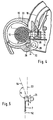
- the tool has an elongated tool body 1 and a handle 2, on which it can be held. Between the walls 3 and 4 of the housing body 1 there is a guide channel 5, initially running in the longitudinal direction of the tool body, for a band 6 made of tough-elastic plastic such as polyamide. It reaches the position shown in FIG. 1 in any way within the section of the channel 5 running in the longitudinal direction of the tool, for example by automatic means (not shown) from a tape magazine or by hand.
- the band has a band tongue 7 and a head 8, the tip 27 of the band tongue pointing to the front end of the tool body, shown on the left in FIG. 1, while the head 8 is located at the rear.
- the guide channel 5 there is a slide head 9 behind the lock 8, the end face of which cooperates with the lock 8 is adapted to the shape of the lock 8 and is fastened to the front end of a flexible steel strip 10 which is wound on a roller 11.
- the head 9 and the steel band 10 together form a slide for pushing the band 6 from the position shown in FIG. 1 to the position (FIG. 3) in which the band is used to bind an object.
- the roller 11 is rotated in the direction of the arrow 14
- the steel strip 10 with the slide head 9 is pushed forward along the guide channel 5.
- the guide channel 5 runs through a bend 49 by approximately 90 ° in order to end parallel to the tool end face.
- the tool has pliers formed by parts 15 and 16. It forms a guide for the band 6 during its path wrapping around the object to be bound.
- Pliers part 15 is pivotable about the axis 17;
- Pliers part 16 is pivotable about the axis 18.
- There are drive and control means provided Provide pivoting of the pliers parts from the open position shown in Fig.1 to other functional positions, as described below. These drive and control means are conventional and therefore not shown and explained.
- the pliers receives an object to be bound, which can be, for example, a bundle of cables 19 (Fig. 2) which are to be firmly bound together by means of the band 6, as in Final stage is shown in Fig. 1.
- an object to be bound which can be, for example, a bundle of cables 19 (Fig. 2) which are to be firmly bound together by means of the band 6, as in Final stage is shown in Fig. 1.
- the band tongue 7 surrounds the cable bundle 19 under tension.
- the free end of the band tongue 7 is guided through the lock 8 and fastened therein.
- the protruding end of the tongue is cut off.
- the pliers parts 15 and 16 can be brought into a closed looping position according to FIG. 3. They contain a guide groove 20, the width of which corresponds approximately to that of the band tongue 7 and the depth of which is considerably greater than the thickness of the band tongue 7.
- the guide groove 20 is delimited at its beginning by a spur 21 which is firmly connected to the pliers part 16.
- the lock 8 When this end position is reached, the lock 8 has also reached its end position, which is determined by the lock holder.
- the lock holder and the lock lie in the end face of the tool body on the circumference of the area enclosed by the wrapping guides in FIG. 4, which defines the circumference of the largest circular cross section that can be accommodated in the wrapping guide.
- the lock holder comprises a housing-fixed mounting part 23, the already mentioned spur 21 and an area 35 behind the spur 21, which is cut out in the plane of the drawing for the passage of the band but laterally above and below the plane of the drawing) can form stop surfaces for the lock.
- the spur 21 and the part 35 together with the mounting part 23 fixed to the housing form a stop which is adapted to the shape of the lock 8 so that its position in the mounting is clearly determined, provided that the lock 8 is pressed against these mounting parts. This is done by the slide head 9, which is designed as a further mounting part.
- the slide head 9 presses the lock 8 against the holding parts 21, 23 and thereby determines exactly the end position of the lock.
- the spur 21 grips between the strap tongue 7, where it is integrally connected to the lock 8, and the mouth of the strap opening 25 indicated by dashed lines for receiving the strap tongue in the lock. This means that the tip of the strap during the wrapping movement (Fig. 3 ) on the front, but must go behind the spur in the final state.
- the arrangement of the spur on the lock body is not absolutely necessary. It is only necessary that the mounting parts 21, 23, 9 all or partially cooperate with the surface of the lock body in such a way that its position is clearly defined.
- the lock is shaped so that the tape originates from the lock approximately in the feed direction and that the tape opening 25 is approximately parallel to this direction. Exact parallelism is not necessary. Rather, when looking at FIG. 3, the band opening could also be a little in the Counterclockwise against the direction shown, so that there is an angle between 180 and 135 °, preferably between 180 and 160 °.
- FIG. 5 This shows the band head 8 with the band opening 25 and the end of the band tongue 7 connected to the lock 8, whose direction 52 at the point where it originates at the lock and the direction 53 of the band opening are parallel in the example shown to each other; they enclose the angle 180 ° with each other.
- the through opening and / or the band origin could be inclined a little to the left in the illustration, as is indicated for the band opening by the direction line 54, which includes an angle ⁇ of approximately 160 ° with the direction 52. Even at a smaller angle down to about 135 °, the goal can still be achieved that the lock is held in the loop guide or in the tool face in such a way that it lies practically on the circumference of the largest possible area that can be enclosed by the loop guide.
- the free end of the strap tongue is located approximately at the end 22 of the loop guide or between this end and the strap lock 8.
- the strap tip is preferably close to the lock 8.
- the band tip must now be inserted into the band opening 25 of the lock. This is done (Fig. 3) in that the pliers part 15 is pivoted further from the looping position shown in Fig. 3 in the direction of arrow 26. This shortens the distance available for receiving the strip tongue 7. Since the lock 8 is held in the meantime, the tape tip 27 in Fig. 3 must move further down.
- the pliers part 15 has reached its end position shown in FIG. 4
- the free end of the band tongue 7 has passed through the band opening 25 and has the gap between two in the direction of the arrow Rotating tensioning rollers 28, 29 reached that grasp the end of the tape and tension.
- a blade 31 is provided, which is guided in its longitudinal direction and is connected to conventional drive and control means, not shown. To carry out the cut, it is moved to the left in FIG. 4, so that its cutting edge cuts through the strip tongue.
- the spur 21 serves as an abutment. It can be sufficient for the spur to form a smooth contact surface for the belt in its abutment area, as shown. Instead, a depression can also be provided at this point in the surface of the spur, which forms a counter-cutting edge or cutting edge which interacts with the blade.
- the distance between the end 22 of the belt guide and the lock 8 is relatively large. This is attributable to the fact that the lock holder is arranged directly on the circumference of the binding cross-section, which is limited in Fig. 4 by the inner edges of the pliers parts 15, 16 and in an intermediate area by the end face of the housing. Consequently, in the distance between the end 22 of the loop guide and the lock holder, the feed path of the band from the guide channel 5 on the one hand and the path of the band from the loop guide 20 on the other hand intersect at an acute angle.
- this angle corresponds approximately to the angle ⁇ between the strip tongue coming from the lock 8 and the through opening 25; however, it does not need to be equal to this complementary angle, since the lock on the way from the guide channel 5 to the lock holder and the band tongue on the Can still experience a deflection from the end of the loop guide to the castle.
- the forwarded tape tip must correctly get out of the guide channel 5 into the start of the looping guide, which is formed between the spur 21 and the cables 19 through the beginning of the groove 20.
- the guide channel 5 is very wide in view of the size of the head 8 and can therefore not give the tape tip sufficient guidance.
- the distance between the end 44 of the guide channel and the spur 21 is also very large, which likewise results in guide uncertainty.
- the invention nevertheless achieves sufficient guiding security for the tape tip in the following manner.
- a rocker 41 projects into the guide channel 5 and can be pivoted about the guide axis 42 fixed to the housing and extending transversely to the plane of the drawing.
- the pivot axis 42 is arranged so that the rocker can be pivoted completely out of the guide channel 5 against the arrow 43 to give the head 8 of the band passage. However, it is acted upon by a spring 44 a so that a restoring force acts on it in the direction of arrow 43.
- the rocker is arranged in such a way that an acute angle 45 results between the section 48 of the wall 3 of the guide channel 5, with which the rocker cooperates, and the rocker 41 from the direction of the band to be advanced.
- the tip 27 of the strap tongue is thus forced between the wall section 48 of the guide channel and the tip of the rocker 41, the strap tongue being pressed against the surface of the wall 48.
- the direction of the wall section 3 is precisely forced on it in the pressure area. This results in a certain direction of the end 27 of the band tongue which extends beyond the end 44 of the wall 3 and which is predetermined in such a way that the tip hits the groove 20 correctly. This direction is independent of the random position that the tape was previously in the guide channel has taken. This is all the more true since the wall 3 is concavely curved in front of and possibly also in the wall section 48.
- the slide 9, 10 can be pulled back into its starting position (FIG. 1) and the bound object can be removed.
- the head 8 shown in the drawing has a fastening part 33 which comprises a plate 34 which projects on all sides. This plate lies behind the spur 21 and partly behind the mounting area 35.
- these parts 21, 35 are firmly connected to the lower pliers part 16, they are forward and during the opening movement of the pliers part in the opening representation shown in FIG. 1 also pivoted down a little.
Landscapes
- Engineering & Computer Science (AREA)
- Mechanical Engineering (AREA)
- Basic Packing Technique (AREA)
- Package Frames And Binding Bands (AREA)
Claims (5)
- Ensemble pour lier un objet, constitué d'un lien (6), qui comprend une languette (7) et un fermoir (8) relié à une extrémité de la languette du lien et présentant un orifice (25) destiné à recevoir l'autre extrémité de la languette du lien, et d'un outil allongé, qui comprend un guide d'encerclement (15, 16, 20) pouvant être ouvert et fermé, situé sur la face frontale de l'outil pour guider le lien autour de l'objet (19), un support de fermoir (35, 21, 23, 9) d'où le guide d'encerclement part et vers lequel il revient, et un canal de guidage (5) destiné à guider le lien, dans le sens de sa longueur, depuis une position de départ jusque dans une position d'encerclement, dans laquelle la languette (7) du lien se trouve dans le guide d'encerclement (20) et le fermoir (8) dans le support de fermoir, caractérisé en ce que le support de fermoir est, sur la face frontale de l'outil, disposé sur la circonférence de la section circulaire la plus grande que puisse recevoir le guide d'encerclement, en ce que l'extrémité (22) du guide d'encerclement et l'extrémité (44) du canal de guidage arrivent du même côté de l'outil, en formant un angle aigu entre elles, en ce que, sur le lien se trouvant dans la position d'encerclement, l'angle entre la direction de l'extrémité, reliée au fermoir (8), de la languette (7) du lien et la direction de l'orifice (25) du lien se situe, du côté tourné vers le guide d'encerclement, entre 135° et 180°, et en ce que le canal de guidage contient, dans son tronçon d'extrémité, un dispositif de guidage (3, 41) pour la languette (7) du lien, qui est formé par une surface de guidage (3), rectiligne ou incurvée sous une forme concave, et par un élément de guidage (41), qui est mobile entre au moins deux positions, celui-ci poussant la languette (7) du lien contre la surface de guidage (3), dans l'une des positions, et étant éloigné de la surface de guidage (3) sur au moins la dimension du fermoir (8), dans l'autre position.
- Outil pour l'ensemble selon la revendication 1, caractérisé en ce que le canal de guidage (5) présente une courbure (49) entre un tronçon s'étendant à peu près parallèlement à la direction longitudinale de l'outil et un tronçon d'extrémité aboutissant au support de fermoir.
- Outil pour l'ensemble selon la revendication 1 ou 2, caractérisé en ce que l'élément de guidage est formé par un bras oscillant (41) qui est chargé par un ressort et qui pénètre sous un angle aigu, par rapport à la direction d'avance du lien (6), dans le canal de guidage (5).
- Outil pour l'ensemble selon la revendication 3, caractérisé en ce que, pour faire avancer le lien (6), il est prévu un poussoir (9, 10), qui présente une surface de commande (46) décollant l'élément de guidage (41) de la surface de guidage (3).
- Outil pour l'ensemble selon l'une des revendications 1 à 4, caractérisé en ce que, de l'autre côté du support de fermoir lorsque l'on regarde depuis l'extrémité (48) du canal de guidage (5), il est prévu un éperon (21), qui sépare le départ du guide d'encerclement (20) de la région dans laquelle l'extrémité libre (30) de la languette du lien est placée après avoir traversé l'orifice (25) du lien.
Applications Claiming Priority (2)
| Application Number | Priority Date | Filing Date | Title |
|---|---|---|---|
| DE9214902U DE9214902U1 (de) | 1992-11-02 | 1992-11-02 | Werkzeug zum Binden eines Gegenstands mittels eines Bandes |
| DE9214902U | 1992-11-02 |
Publications (2)
| Publication Number | Publication Date |
|---|---|
| EP0596363A1 EP0596363A1 (fr) | 1994-05-11 |
| EP0596363B1 true EP0596363B1 (fr) | 1997-01-15 |
Family
ID=6885579
Family Applications (1)
| Application Number | Title | Priority Date | Filing Date |
|---|---|---|---|
| EP93117249A Expired - Lifetime EP0596363B1 (fr) | 1992-11-02 | 1993-10-25 | Arrangement pour encercler un objet |
Country Status (4)
| Country | Link |
|---|---|
| US (1) | US5417252A (fr) |
| EP (1) | EP0596363B1 (fr) |
| DE (2) | DE9214902U1 (fr) |
| ES (1) | ES2099343T3 (fr) |
Cited By (1)
| Publication number | Priority date | Publication date | Assignee | Title |
|---|---|---|---|---|
| US10457429B1 (en) | 2016-09-03 | 2019-10-29 | Johnson International Corporation | Pair of jaws for a twist-tying machine |
Families Citing this family (13)
| Publication number | Priority date | Publication date | Assignee | Title |
|---|---|---|---|---|
| DE29617651U1 (de) * | 1996-10-10 | 1998-02-05 | Paul Hellermann GmbH, 25421 Pinneberg | Anordnung zum Binden eines Gegenstands, insbesondere eines Kabelbaums |
| IT1286370B1 (it) * | 1996-10-31 | 1998-07-08 | Thomas & Betts Corp | Utensile automatico per la installazione di fascette serracavi |
| USD412820S (en) | 1997-12-05 | 1999-08-17 | Ching Lu Lee | Hand held bundler |
| US5957165A (en) * | 1997-12-15 | 1999-09-28 | Sumitomo Wiring Systems, Ltd. | Apparatus for winding and tightening a band clip around a wiring harness |
| US7913957B2 (en) * | 2006-05-08 | 2011-03-29 | Panduit Corp. | Mounting device and apparatus for use with studs comprising T-shaped channels |
| US8528603B2 (en) * | 2007-09-21 | 2013-09-10 | Panduit Corp. | Tie guide channel for cable tie installation tool |
| US9526502B2 (en) * | 2008-09-10 | 2016-12-27 | Unique Surgical Innovations Llc | Surgical string applicator for anastomosis surgery |
| US20100139805A1 (en) * | 2008-12-10 | 2010-06-10 | Panduit Corp. | Power Tool for Stainless Steel Metal Locking Ties |
| TWI516415B (zh) * | 2008-12-12 | 2016-01-11 | 美克司股份有限公司 | 鐵筋捆紮機 |
| DE102019107073B4 (de) * | 2019-03-20 | 2021-02-11 | Lisa Dräxlmaier GmbH | Vorrichtung und verfahren zum automatisierten abbinden von kabeln |
| EP4163215A1 (fr) | 2021-10-01 | 2023-04-12 | HellermannTyton GmbH | Dispositif d'outil de fardelage automatique optimisé pour une plage d'épaisseurs de sangles d'une seule pièce |
| US11891200B1 (en) * | 2022-08-24 | 2024-02-06 | Zevforce,Llc | Cable tie cartridge |
| DE202022002179U1 (de) | 2022-10-06 | 2024-01-11 | Hellermanntyton Gmbh | Automatische Bündelwerkzeugvorrichtung mit Führungseinheit für verformte und/oder lose einteilige Bänder |
Family Cites Families (5)
| Publication number | Priority date | Publication date | Assignee | Title |
|---|---|---|---|---|
| US3946769A (en) * | 1974-03-12 | 1976-03-30 | Panduit Corporation | Automatic cable tie installation tool |
| US3976108A (en) * | 1974-03-12 | 1976-08-24 | Panduit Corporation | Automatic cable tie installation tool |
| US4495972A (en) * | 1980-02-27 | 1985-01-29 | Bowthorpe-Hellermann Limited | Automatic tie gun |
| GB8907143D0 (en) * | 1989-03-30 | 1989-05-10 | Bowthorpe Hellermann Ltd | Automatic tie gun |
| DE59000226D1 (de) * | 1989-11-15 | 1992-09-03 | Hellermann Gmbh P | Band und werkzeug zum umschlingen und spannen um langgestreckte gegenstaende. |
-
1992
- 1992-11-02 DE DE9214902U patent/DE9214902U1/de not_active Expired - Lifetime
-
1993
- 1993-10-25 EP EP93117249A patent/EP0596363B1/fr not_active Expired - Lifetime
- 1993-10-25 ES ES93117249T patent/ES2099343T3/es not_active Expired - Lifetime
- 1993-10-25 DE DE59305137T patent/DE59305137D1/de not_active Expired - Lifetime
- 1993-10-29 US US08/145,963 patent/US5417252A/en not_active Expired - Lifetime
Cited By (1)
| Publication number | Priority date | Publication date | Assignee | Title |
|---|---|---|---|---|
| US10457429B1 (en) | 2016-09-03 | 2019-10-29 | Johnson International Corporation | Pair of jaws for a twist-tying machine |
Also Published As
| Publication number | Publication date |
|---|---|
| US5417252A (en) | 1995-05-23 |
| DE59305137D1 (de) | 1997-02-27 |
| DE9214902U1 (de) | 1994-03-03 |
| EP0596363A1 (fr) | 1994-05-11 |
| ES2099343T3 (es) | 1997-05-16 |
Similar Documents
| Publication | Publication Date | Title |
|---|---|---|
| EP0835809B1 (fr) | Dispositif pour encercler un objet, en particulier un faisceau de câbles | |
| DE2401369A1 (de) | Vorrichtung zum verschliessen von blutgefaessen | |
| DE2300782C3 (de) | Werkzeug zum Spannen und Abschneiden eines mit einem Schloß versehenen, um einen Gegenstand gelegten Bandes | |
| DE2536366C3 (de) | Bandführungseinrichtung für eine Bindemaschine | |
| DE2101875B2 (de) | Vorrichtung zum Aufsetzen von Schiebern auf Verschlußelemente | |
| DE2510575A1 (de) | Automatisches werkzeug zur anbringung von kabelbaendern | |
| DE2214819C3 (de) | Kabelbandspannzange | |
| EP0596363A1 (fr) | Arrangement pour encercler un objet | |
| DE3426251A1 (de) | Umreifungsvorrichtung | |
| EP0565968B1 (fr) | Dispositif de montage pour attacher des faisceaux de câbles | |
| EP0428116B1 (fr) | Bande et outil de cerclage et de tension pour objets allongés | |
| DE3131224C2 (de) | Umreifungsgerät für Stahlbänder | |
| DE2623907B2 (de) | Straffzieheinrichtung | |
| EP0596368B1 (fr) | Arrangement pour ligaturer un objet, en particulier un faisceau de câbles | |
| EP1479610B1 (fr) | Tête de scellage pour une machine de cerclage | |
| EP0596370B1 (fr) | Arrangement de liage | |
| EP1231141A1 (fr) | Outil pour appliquer des liens, notamment à des faisceaux de câble | |
| EP0596369B1 (fr) | Appareil pour encercler un objet au moyen d'une bande | |
| DE2803511C2 (de) | Vorrichtung zum Vorlegen einer Aufhängeschlaufe zur Verwendung an einer Maschine zum Verschließen von Wursthüllen | |
| EP1050462B1 (fr) | Dispositif de tension pour machine de cerclage | |
| DE2748712A1 (de) | Presswerkzeug | |
| DE69829550T2 (de) | Ultraschall-bindewerkzeug | |
| DE3426252A1 (de) | Umreifungsvorrichtung | |
| DE1164921B (de) | Knuepfer fuer Bindemaschinen | |
| DE2555710A1 (de) | Zange zum banderolieren von gegenstaenden |
Legal Events
| Date | Code | Title | Description |
|---|---|---|---|
| PUAI | Public reference made under article 153(3) epc to a published international application that has entered the european phase |
Free format text: ORIGINAL CODE: 0009012 |
|
| AK | Designated contracting states |
Kind code of ref document: A1 Designated state(s): DE ES FR GB IT PT SE |
|
| 17P | Request for examination filed |
Effective date: 19941107 |
|
| 17Q | First examination report despatched |
Effective date: 19951124 |
|
| GRAG | Despatch of communication of intention to grant |
Free format text: ORIGINAL CODE: EPIDOS AGRA |
|
| GRAH | Despatch of communication of intention to grant a patent |
Free format text: ORIGINAL CODE: EPIDOS IGRA |
|
| GRAH | Despatch of communication of intention to grant a patent |
Free format text: ORIGINAL CODE: EPIDOS IGRA |
|
| GRAA | (expected) grant |
Free format text: ORIGINAL CODE: 0009210 |
|
| AK | Designated contracting states |
Kind code of ref document: B1 Designated state(s): DE ES FR GB IT PT SE |
|
| RAP2 | Party data changed (patent owner data changed or rights of a patent transferred) |
Owner name: PAUL HELLERMANN GMBH |
|
| REF | Corresponds to: |
Ref document number: 59305137 Country of ref document: DE Date of ref document: 19970227 |
|
| ITF | It: translation for a ep patent filed | ||
| GBT | Gb: translation of ep patent filed (gb section 77(6)(a)/1977) |
Effective date: 19970403 |
|
| REG | Reference to a national code |
Ref country code: ES Ref legal event code: FG2A Ref document number: 2099343 Country of ref document: ES Kind code of ref document: T3 |
|
| ET | Fr: translation filed | ||
| REG | Reference to a national code |
Ref country code: PT Ref legal event code: SC4A Free format text: AVAILABILITY OF NATIONAL TRANSLATION Effective date: 19970314 |
|
| PLBE | No opposition filed within time limit |
Free format text: ORIGINAL CODE: 0009261 |
|
| STAA | Information on the status of an ep patent application or granted ep patent |
Free format text: STATUS: NO OPPOSITION FILED WITHIN TIME LIMIT |
|
| 26N | No opposition filed | ||
| REG | Reference to a national code |
Ref country code: GB Ref legal event code: IF02 |
|
| PGFP | Annual fee paid to national office [announced via postgrant information from national office to epo] |
Ref country code: FR Payment date: 20121113 Year of fee payment: 20 |
|
| PGFP | Annual fee paid to national office [announced via postgrant information from national office to epo] |
Ref country code: SE Payment date: 20121024 Year of fee payment: 20 Ref country code: GB Payment date: 20121023 Year of fee payment: 20 Ref country code: IT Payment date: 20121026 Year of fee payment: 20 Ref country code: ES Payment date: 20121023 Year of fee payment: 20 Ref country code: PT Payment date: 20120426 Year of fee payment: 20 |
|
| PGFP | Annual fee paid to national office [announced via postgrant information from national office to epo] |
Ref country code: DE Payment date: 20121218 Year of fee payment: 20 |
|
| REG | Reference to a national code |
Ref country code: DE Ref legal event code: R071 Ref document number: 59305137 Country of ref document: DE |
|
| REG | Reference to a national code |
Ref country code: DE Ref legal event code: R071 Ref document number: 59305137 Country of ref document: DE |
|
| REG | Reference to a national code |
Ref country code: PT Ref legal event code: MM4A Free format text: MAXIMUM VALIDITY LIMIT REACHED Effective date: 20131025 |
|
| REG | Reference to a national code |
Ref country code: GB Ref legal event code: PE20 Expiry date: 20131024 |
|
| REG | Reference to a national code |
Ref country code: SE Ref legal event code: EUG |
|
| PG25 | Lapsed in a contracting state [announced via postgrant information from national office to epo] |
Ref country code: PT Free format text: LAPSE BECAUSE OF EXPIRATION OF PROTECTION Effective date: 20131104 Ref country code: GB Free format text: LAPSE BECAUSE OF EXPIRATION OF PROTECTION Effective date: 20131024 Ref country code: DE Free format text: LAPSE BECAUSE OF EXPIRATION OF PROTECTION Effective date: 20131026 |
|
| REG | Reference to a national code |
Ref country code: ES Ref legal event code: FD2A Effective date: 20140925 |
|
| PG25 | Lapsed in a contracting state [announced via postgrant information from national office to epo] |
Ref country code: ES Free format text: LAPSE BECAUSE OF EXPIRATION OF PROTECTION Effective date: 20131026 |