EP0596382A1 - Sac à poussières pour aspirateur - Google Patents
Sac à poussières pour aspirateur Download PDFInfo
- Publication number
- EP0596382A1 EP0596382A1 EP93117300A EP93117300A EP0596382A1 EP 0596382 A1 EP0596382 A1 EP 0596382A1 EP 93117300 A EP93117300 A EP 93117300A EP 93117300 A EP93117300 A EP 93117300A EP 0596382 A1 EP0596382 A1 EP 0596382A1
- Authority
- EP
- European Patent Office
- Prior art keywords
- opening
- filter bag
- holding plate
- dust filter
- layers
- Prior art date
- Legal status (The legal status is an assumption and is not a legal conclusion. Google has not performed a legal analysis and makes no representation as to the accuracy of the status listed.)
- Granted
Links
- 239000000428 dust Substances 0.000 title claims abstract description 35
- 239000000463 material Substances 0.000 claims abstract description 22
- 239000000123 paper Substances 0.000 claims description 9
- 239000007787 solid Substances 0.000 claims description 4
- 238000009751 slip forming Methods 0.000 claims 1
- 230000037431 insertion Effects 0.000 abstract 1
- 238000003780 insertion Methods 0.000 abstract 1
- 239000010410 layer Substances 0.000 description 52
- 238000007789 sealing Methods 0.000 description 10
- 241001295925 Gegenes Species 0.000 description 4
- 238000005520 cutting process Methods 0.000 description 3
- 238000011161 development Methods 0.000 description 3
- 230000018109 developmental process Effects 0.000 description 3
- 239000002245 particle Substances 0.000 description 3
- 230000000717 retained effect Effects 0.000 description 3
- 239000000853 adhesive Substances 0.000 description 2
- 238000004026 adhesive bonding Methods 0.000 description 2
- 230000015572 biosynthetic process Effects 0.000 description 2
- 238000007654 immersion Methods 0.000 description 2
- 238000000034 method Methods 0.000 description 2
- 238000003032 molecular docking Methods 0.000 description 2
- 230000002093 peripheral effect Effects 0.000 description 2
- 238000003860 storage Methods 0.000 description 2
- 238000009825 accumulation Methods 0.000 description 1
- 230000001070 adhesive effect Effects 0.000 description 1
- 239000012790 adhesive layer Substances 0.000 description 1
- 238000007664 blowing Methods 0.000 description 1
- 239000002131 composite material Substances 0.000 description 1
- 238000001514 detection method Methods 0.000 description 1
- 238000007688 edging Methods 0.000 description 1
- 210000004905 finger nail Anatomy 0.000 description 1
- 239000012943 hotmelt Substances 0.000 description 1
- 239000012528 membrane Substances 0.000 description 1
- 230000000149 penetrating effect Effects 0.000 description 1
- 239000002985 plastic film Substances 0.000 description 1
- 229920006255 plastic film Polymers 0.000 description 1
- 239000002243 precursor Substances 0.000 description 1
- 238000003825 pressing Methods 0.000 description 1
- 230000029058 respiratory gaseous exchange Effects 0.000 description 1
- 239000012945 sealing adhesive Substances 0.000 description 1
- 238000004904 shortening Methods 0.000 description 1
- 230000007704 transition Effects 0.000 description 1
Images







Classifications
-
- A—HUMAN NECESSITIES
- A47—FURNITURE; DOMESTIC ARTICLES OR APPLIANCES; COFFEE MILLS; SPICE MILLS; SUCTION CLEANERS IN GENERAL
- A47L—DOMESTIC WASHING OR CLEANING; SUCTION CLEANERS IN GENERAL
- A47L9/00—Details or accessories of suction cleaners, e.g. mechanical means for controlling the suction or for effecting pulsating action; Storing devices specially adapted to suction cleaners or parts thereof; Carrying-vehicles specially adapted for suction cleaners
- A47L9/10—Filters; Dust separators; Dust removal; Automatic exchange of filters
- A47L9/14—Bags or the like; Rigid filtering receptacles; Attachment of, or closures for, bags or receptacles
- A47L9/1427—Means for mounting or attaching bags or filtering receptacles in suction cleaners; Adapters
- A47L9/1436—Connecting plates, e.g. collars, end closures
- A47L9/1445—Connecting plates, e.g. collars, end closures with closure means
-
- A—HUMAN NECESSITIES
- A47—FURNITURE; DOMESTIC ARTICLES OR APPLIANCES; COFFEE MILLS; SPICE MILLS; SUCTION CLEANERS IN GENERAL
- A47L—DOMESTIC WASHING OR CLEANING; SUCTION CLEANERS IN GENERAL
- A47L9/00—Details or accessories of suction cleaners, e.g. mechanical means for controlling the suction or for effecting pulsating action; Storing devices specially adapted to suction cleaners or parts thereof; Carrying-vehicles specially adapted for suction cleaners
- A47L9/10—Filters; Dust separators; Dust removal; Automatic exchange of filters
- A47L9/14—Bags or the like; Rigid filtering receptacles; Attachment of, or closures for, bags or receptacles
- A47L9/1427—Means for mounting or attaching bags or filtering receptacles in suction cleaners; Adapters
- A47L9/1436—Connecting plates, e.g. collars, end closures
Definitions
- the invention relates to a dust filter bag for a vacuum cleaner, with a holding plate made of a solid paper material, for example cardboard-paper material, with which a dust bag is, for example, adhesively bonded, which holding plate has a sealable opening for an intake pipe of a vacuum cleaner, the Opening can be closed with a separate closure element, which can be moved from an open position, in a secondary arrangement to the opening, into a closed position.
- the bag-forming filter material is fastened in the vicinity of the edge on one broad surface of the holding plate, preferably in a sealing adhesive connection.
- the bag body can be folded to save space by folding the support plate down into the plane of the wall-forming layers of the bag body.
- a dust filter bag of this type is known for example from DE-OS 2 407 478.
- the separate locking tab there consists of a strip which is displaceably guided between two layers of the holding plate and which has a hole. In the case of a hole that is approximately congruent to the opening of the holding plate, the connecting piece of the suction pipe can be docked there in an operationally suitable manner.
- a strip holding in self-adhesive connection can also be used as the closure flap, which strip can be transferred from its storage meander fold into a position covering and closing the opening.
- the object of the invention is to design an improved dust filter bag.
- a dust filter bag that is structurally and operationally improved is implemented.
- the opening area which is exposed to not inconsiderable mechanical stress, is highly stable.
- the procedure is such that the closure element rests on at least two layers of the solid paper material, at least in an open position, and that a rubber ring seal is gripped between these two layers in the area of the opening.
- a secure setting of a rubber ring seal for the connecting piece of the vacuum cleaner has been achieved.
- the holding plate also has, at least in the region of the opening, three layers arranged one above the other in a stacked arrangement.
- the area of the opening is not only made of the highly stable three-layer laminate, it is also realized that the closure element, for example a closure tab, is only within the contours of the holding plate, both in the open and in the closed position.
- the closure element for example a closure tab
- a joint between two (lower) layers is also used to accommodate the sealing element.
- the fixation of the sealing element can be included in the laminate securing, for example by an adhesive or hot-melt layer also capturing the rubber ring seal in a position-securing manner. There is no additional fastening effort, as would be necessary, for example, with an overlying sealing film. Since a rather narrow peripheral bond zone is sufficient for the rubber ring seal, the stabilized composite material runs through to the edge of the support plate.
- this edge generally has a specific contour to a corresponding storage zone of the vacuum cleaner, nose-like projections etc. are still very stable in themselves, even with a small dimension, even with a two-layer shape.
- the only partial three-layer structure in the area of the opening leaves layer material available for further development measures.
- an opening edge area of the middle layer is set back from opening edges of the upper and lower layers to form a latching opening. This creates an advantageous prerequisite for securing the position of a sealing tab sealing from the outside.
- the middle layer has a larger diameter than the upper and lower layers with a concentric arrangement of the diameters.
- the latching opening is supplemented to form a circumferential latching opening, so that it is not even necessary to assign the closure tab in a particularly targeted manner.
- the holding plate be formed in three layers continuously on the edge side. This has the advantage of supporting the holding plate in the device-side receptacle on an equal basis, that is to say completely without tilting, the region remote from the opening being able to remain double-layered, ie layer material for other purposes Is available, for example, from this residual material, a foldable closure flap is designed over the opening.
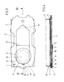
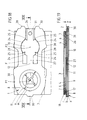
- All four illustrated exemplary embodiments show a dust filter bag, for example for a vacuum cleaner, which ends on the docking side with a hard part in the form of a holding plate 1.
- the actual bag 3 extends from the back surface 2 and is glued to the edge.
- the holding plate 1 consists of a cardboard paper material.
- the holding plate 1 has a contour K, within which a closure element 10 (which will be explained in more detail below) is accommodated both in the open position (for example FIG. 1) and in the closed position (for example FIG. 10).
- a closure element 10 which will be explained in more detail below
- the second layer b also offers full-area support for the closure element 10.
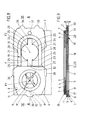
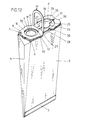
- the bag 3 can be folded to save space. When folded, it can be placed against the rear surface 2 (see, for example, FIG. 2). For this purpose, the narrow sides 4 of the bag 3 are drawn in in a V-shape. On the holding plate side, the inner fold branches into a Y-shaped branch, which ends directed towards the corner zones of the narrow side of the holding plate 1. The bottom of the bag 3 is closed by folding and gluing. The fold-out bears the reference number 5.
- the open or mouth-side bag edge is fixed to the rear surface 2 of the holding plate 1 by angling the edge 6 there and gluing to said surface 2.
- the corresponding adhesive layer is designated by 7.
- the basically rectangular holding plate 1 is constructed continuously or predominantly in three layers.
- the individual positions of the same outline are labeled a, b, c.
- the uppermost layer a which is furthest from the bag, forms the front surface 8 of the holding plate 1.
- the suction pipe or connecting piece of the vacuum cleaner not shown, is docked.
- the individual layers a to c best hen preferably from a single folding blank, which is either placed zigzag one on top of the other or by folding a free layer between two other, ie folding two end positions against each other (see FIG. 6).
- the individual layers a to c are broken through to form an opening 9. It is a circular opening. Their center is located in the plane of symmetry of the holding plate 1 which also forms the cutting line, the two halves of which are thus designed to be mirror-identical.
- Said opening 9 can be sealed from the outside by means of a locking tab 10.
- the latter is an integral part of the top layer a, that is to say formed from its material section by cutting free. With the aid of such a closure flap 10, the known aspiration of the dust-filled bag 3 can be reduced or even avoided when the volume is reduced by touching it.
- the free cut is continuously labeled F.
- the cardboard paper material has three layers, at least in the region of the opening 9.
- the three-layer laminate stabilizes the docking area for the suction pipe or the suction nozzle of the vacuum cleaner, but also has the essential advantage of accommodating a rubber ring seal 11 between the joint-forming contact surfaces of two layers, which is easy to assign. They are preferably arranged between the second and third layers b and c. The edging can be seen particularly clearly from the sectional views.
- the rubber ring seal 11 it is a highly elastic ring membrane whose clear diameter D1 is smaller than the clear diameter of the circular opening D2. Of course, it can also be a plastic film with the corresponding sealing property.
- the radial clearance depth of the rubber ring seal corresponds approximately to the width of the border between the layers b and c.
- the border depth is shown somewhat broader in the drawings.
- the clear diameter D1 of the rubber ring seal 11 is dimensionally greater than that of the intake pipe or intake pipe, not shown.
- the lateral wall of the latter runs approximately in the central region of the free-standing length of the rubber sealing ring 11.
- the remaining length or the remaining area of the holding plate 1 is at least two layers. This area is expediently used in relation to the uppermost layer a to form the locking tab 10. In this way, no separate locking member needs to be manufactured and assigned. If the corresponding cut-out forming free cut does not go, or does not go essentially everywhere to the periphery of this position, the basic thickness x is nevertheless retained in the area of the holding plate 1 forming the make-up tab 10.
- All of the locking tabs 10 also fold around a hinge zone 12 lying transversely to the length of the rectangular holding plate 1.
- the latter is formed by a fold line.
- the ease of folding can be increased, for example, by a perforation 13.
- the center point P1 or center point of the opening 9 is at least as far from the hinge zone 12 as the center point P2 of the locking tab 10. Both lie on the plane or line of symmetry formed by the intersection lines.
- the closure flap 10 has an elongated shield-like shape with an arcuate edge 14 formed at the free end. Its radius corresponds to that of the opening 9. The width y of this closure flap 10 corresponds at most to the diameter D2.
- a locking lug 15 In front of this locking lug 15, the top layer a leaves a cleared cut-out area as an access recess 16. The latter is about the size of a fingertip, so that the locking lug 15 can easily be reached under with the fingernail to close the locking tab 10 from its immersion position in the uppermost position a into the closed position shown in FIG. 4.
- latch 15 and latch opening 17 are expediently semicircular. The latching force achieved is so great that even with the holding plate 1 of the dust filter bag pointing downward, no dirt particles can fall out of the interior of the bag 3. Aspiration is also significantly reduced.
- the middle layer b has a larger recess associated with the opening 9 than the top and bottom layers a, c.
- the third layer c can also have a bulge 18 corresponding to the outline, congruent with the latching opening 17. Due to the high elasticity or flexibility of the rubber ring seal 11, this allows the catch 15 to dodge slightly in this direction, but is springed back by the zone of the rubber ring seal 11 which is released via the bulge 18.
- the procedure is alternatively such that with a circular configuration of the opening 9 the middle layer b has a somewhat larger diameter than the diameter D2 of the top (a) and bottom layer c in corresponding to a concentric arrangement of the diameters, which leads to a larger latching grip under the locking flap 10 if it has a correspondingly widened latching lug 15 or is immersed with the entire edge 14 in a latching manner.
- a further development is based on the fact that the rest, i.e. the area of the holding plate 1 facing away from the opening 9, in addition to the formation of the locking tab 10, is also used to create a holding bracket 19.
- the latter has a U-shape. Its U-web 20 is circular.
- the adjoining U-legs 21, which run parallel to the opening 9, are each rooted in a hinge zone 23. This also extends transversely to the length of the holding plate 1.
- the hinge zones 23 are flush with the hinge zone 12 of the locking tab 10.
- the hinge zones 23 also become formed by fold lines of the blank and can also be perforated.
- the disposal position is shown in FIG. 12. There, the holding bracket 19 is angled into a folded-up position.
- the dust filter bag can be easily removed from the vacuum cleaner housing and carried to the disposal site. Before that, of course, the locking tab 10 is brought into the locking position.
- the closure tab 10 differs structurally from that of the first one in that its closing active plate part now does not overlap the rubber ring seal 11, but rather engages under rubber ring seal 11 with sections of its edge. This can be seen particularly clearly from FIGS. 10 and 11.
- the web 27 leads to the hinge zone 12 of the locking tab 10, which is cut free in the interior of the U-shaped bracket 9.
- the tongue 26 diametrically opposite the web 27 is supported on the opening edge 9 'of the uppermost layer a and, like the web 27, prevents the closure tab 10 from hanging into the interior of the bag 3 in the pressed-in position. Rather, the radially outgoing material extensions cause a resilient pressing force against the underside of the rubber ring seal 11 and, moreover, a completely perfect seal.
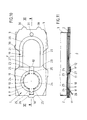
- bracket 19 is not made of the material of the rest, i.e. area of the holding plate 1 remote from the opening is cut out, but from the areas having the opening 9.
- This retaining bracket also has a U-shape and extends concentrically and radially outwards at a distance from the opening edge 9 'of the opening 9. Beyond this cut-out, material of the uppermost layer a remains, so that the basic thickness x is retained up to the periphery.
- Said gripping niches 28 can be included in the formation of an assignment module in that projections on the housing side protrude there (not shown).
- the holding plate 1 has several tooth-like, outward facing edges jumps 30, which enter into corresponding recesses in the housing and also serve to ensure tamper evidence.
- Such tooth-like projections 30 prove to be quite stable, due to the predominantly three-layer structure.
- the hinge zone 23 does not extend in the transverse central plane of the holding plate, but rather is offset somewhat in the direction of the opening 9. This compensates for the larger accumulation of material in the holding plate 1 there.
- detection of the retaining bracket 19 results in a slight lifting of this zone, so that in any case a pouring position of the dust filter bag is avoided, so that no dirt particles can fall out when the closure position is missed. The mouth is higher.
- the fourth exemplary embodiment differs from the former in that the component forming the tongue 26 is cut free in a zone extending to the edge of the holding plate 1, that is to say it has a longer gripping length.
- the basic thickness x remains essentially unchanged, since the material of the uppermost layer a continues continuously laterally into the narrow tooth-like projections 30 there. There is a fork-shaped section.
- V-shaped incisions 25 at the transition area to the web 27 no longer start directly in the band-shaped inlet zone between the web 27 and the disk-shaped section of the closure flap 10, but offset at an angle. This results in a slight shortening of the peripheral portions 24 in the circumferential direction, which can thereby be “threaded” even more easily into the opening 9 in order to come under the rubber ring seal 11.
- a hole 31 arranged in the remaining area of the holding plate 1 and penetrating all three layers. This extends near the edge and lies in the plane of symmetry of the holding plate 1.
Landscapes
- Engineering & Computer Science (AREA)
- Mechanical Engineering (AREA)
- Filters For Electric Vacuum Cleaners (AREA)
- Control And Other Processes For Unpacking Of Materials (AREA)
- Medicines That Contain Protein Lipid Enzymes And Other Medicines (AREA)
Priority Applications (1)
| Application Number | Priority Date | Filing Date | Title |
|---|---|---|---|
| DE9321543U DE9321543U1 (de) | 1992-11-03 | 1993-10-26 | Staubfilterbeutel für einen Staubsauger |
Applications Claiming Priority (2)
| Application Number | Priority Date | Filing Date | Title |
|---|---|---|---|
| DE4237035A DE4237035A1 (de) | 1992-11-03 | 1992-11-03 | Staubfilterbeutel für einen Staubsauger |
| DE4237035 | 1992-11-03 |
Publications (2)
| Publication Number | Publication Date |
|---|---|
| EP0596382A1 true EP0596382A1 (fr) | 1994-05-11 |
| EP0596382B1 EP0596382B1 (fr) | 1999-08-04 |
Family
ID=6471957
Family Applications (1)
| Application Number | Title | Priority Date | Filing Date |
|---|---|---|---|
| EP93117300A Expired - Lifetime EP0596382B1 (fr) | 1992-11-03 | 1993-10-26 | Sac à poussières pour aspirateur |
Country Status (16)
| Country | Link |
|---|---|
| US (1) | US5468271A (fr) |
| EP (1) | EP0596382B1 (fr) |
| JP (1) | JPH06339446A (fr) |
| AT (1) | ATE182765T1 (fr) |
| AU (1) | AU669006B2 (fr) |
| CA (1) | CA2102158A1 (fr) |
| CZ (1) | CZ285576B6 (fr) |
| DE (2) | DE4237035A1 (fr) |
| ES (1) | ES2134234T3 (fr) |
| HU (1) | HU212079B (fr) |
| MX (1) | MX9306823A (fr) |
| NZ (1) | NZ250095A (fr) |
| PL (1) | PL172536B1 (fr) |
| SI (1) | SI9300577A (fr) |
| SK (1) | SK282519B6 (fr) |
| ZA (1) | ZA938174B (fr) |
Cited By (1)
| Publication number | Priority date | Publication date | Assignee | Title |
|---|---|---|---|---|
| CN103876686A (zh) * | 2012-12-21 | 2014-06-25 | Seb公司 | 吸尘器及其吸尘器袋 |
Families Citing this family (30)
| Publication number | Priority date | Publication date | Assignee | Title |
|---|---|---|---|---|
| FR2713076B1 (fr) * | 1993-12-03 | 1996-01-12 | Seb Sa | Dispositif d'obturation et d'éjection de sac d'aspirateur. |
| DE4432105A1 (de) * | 1994-09-09 | 1996-03-14 | Hoechst Ag | Fluoro-alkyl/alkenyl-substituierte Benzoylguanidine, Verfahren zu ihrer Herstellung, ihre Verwendung als Medikament oder Diagnostikum sowie sie enthaltendes Medikament |
| US5613989A (en) * | 1995-10-10 | 1997-03-25 | Home Care Industries, Inc. | Self-aligning self-sealing vacuum bag |
| US5688298A (en) * | 1995-10-10 | 1997-11-18 | Home Care Industries, Inc. | Self-aligning, self-sealing vacuum bag |
| DE29601812U1 (de) * | 1996-02-03 | 1996-03-14 | Branofilter GmbH, 90599 Dietenhofen | Anschlußstück eines Filterbeutels für Staubsauger |
| US5725620A (en) * | 1996-06-10 | 1998-03-10 | Home Care Industries, Inc. | Manually closable vacuum cleaner bag |
| AU3907400A (en) * | 1999-04-06 | 2000-10-23 | Oreck Holdings, Llc | Vacuum cleaner bag closure |
| US6379408B1 (en) | 1999-04-06 | 2002-04-30 | Oreck Holdings, Llc | Mounting and closure structure for a bag, such as a vacuum cleaner bag |
| DE19948909A1 (de) * | 1999-10-11 | 2001-04-12 | Vorwerk Co Interholding | Filterbeutel für einen Staubsauger |
| DE20013364U1 (de) * | 2000-08-03 | 2001-02-08 | Branofilter GmbH, 90599 Dietenhofen | Filterbeutel |
| US6733555B1 (en) | 2001-02-28 | 2004-05-11 | Wildwood Industries, Inc. | Vacuum bag collar |
| US6746501B1 (en) | 2001-02-28 | 2004-06-08 | Wildwood Industries, Inc. | Vacuum bag collar with rotatable closure |
| JP4629288B2 (ja) * | 2001-09-28 | 2011-02-09 | 東芝コンシューマエレクトロニクス・ホールディングス株式会社 | 掃除機用集塵フィルタ及びこれを備える電気掃除機 |
| US20080016646A1 (en) * | 2005-01-10 | 2008-01-24 | Martin Gagnon | Housing assembly for a vacuum |
| US7461430B2 (en) * | 2005-01-10 | 2008-12-09 | Broan-Nutone Llc | Vacuum system and method |
| US20070095031A1 (en) * | 2005-11-03 | 2007-05-03 | Zahuranec Terry L | Mounting collar for a filter bag |
| US7799107B2 (en) * | 2006-03-15 | 2010-09-21 | Techtronic Floor Care Technology Limited | Self-sealing bag arrangement for a floor cleaning device |
| DE102007053151B4 (de) | 2007-11-08 | 2025-05-08 | Wolf Pvg Gmbh & Co. Kommanditgesellschaft | Halteplatte für einen Staubsaugerbeutel und Verfahren zu deren Herstellung |
| DE102011105384A1 (de) * | 2011-06-20 | 2012-12-20 | Alexander Patzig | Halteplatte für Staubsaugerbeutel |
| USD657510S1 (en) * | 2011-08-12 | 2012-04-10 | Electrolux Home Care Products, Inc. | Vacuum cleaner bag flange |
| US8439997B2 (en) | 2011-08-16 | 2013-05-14 | Nss Enterprises, Inc. | Vacuum sweeper apparatus including a filter bag and a method of installation |
| USD664317S1 (en) * | 2011-08-16 | 2012-07-24 | Nss Enterprises, Inc. | Top plate for a filter bag |
| CN104228266A (zh) * | 2014-09-19 | 2014-12-24 | 上海曾曦净化科技有限公司 | 一种用于吸尘器过滤袋卡口板的新型复合板材及其加工方法 |
| EP4331455A3 (fr) | 2016-05-09 | 2024-05-29 | Aktiebolaget Electrolux | Récipient à poussière pour aspirateur |
| EP3318166A1 (fr) * | 2016-11-07 | 2018-05-09 | HILTI Aktiengesellschaft | Dispositif de bride pour un dispositif de filtre |
| USD868405S1 (en) * | 2017-02-15 | 2019-11-26 | Miele & Cie. Kg | Connection element for vacuum cleaner bag |
| WO2019232056A1 (fr) * | 2018-05-29 | 2019-12-05 | Gentherm Medical, Llc | Ensemble orifice d'entrée monobloc |
| USD1032978S1 (en) * | 2021-04-20 | 2024-06-25 | Vacuum Technologies, Llc | Aperture cover |
| USD1019034S1 (en) * | 2022-01-07 | 2024-03-19 | Haowen Mo | Vacuum cleaner dust storage bag |
| USD975391S1 (en) * | 2022-04-28 | 2023-01-10 | Shenzhen Kuajingjianbing E-Commerce Co., Ltd | Vacuum bag cover |
Citations (5)
| Publication number | Priority date | Publication date | Assignee | Title |
|---|---|---|---|---|
| NL7305715A (fr) * | 1972-04-24 | 1973-10-26 | ||
| EP0009471A1 (fr) * | 1978-09-25 | 1980-04-02 | Aktiebolaget Electrolux | Sac à poussière pour un aspirateur |
| US4861357A (en) * | 1988-05-10 | 1989-08-29 | Gavin Thomas W | Vacuum cleaner bag collar |
| EP0510314A1 (fr) * | 1991-04-24 | 1992-10-28 | Vorwerk & Co. Interholding GmbH | Sac à poussières |
| EP0510309A1 (fr) * | 1991-04-24 | 1992-10-28 | Vorwerk & Co. Interholding GmbH | Sac à poussières |
Family Cites Families (8)
| Publication number | Priority date | Publication date | Assignee | Title |
|---|---|---|---|---|
| FI31735A (fi) * | 1956-03-01 | 1961-04-10 | Hoover Ltd | Tillslutningsanordning vid filterpåsar för dammsugare |
| US3417550A (en) * | 1965-10-04 | 1968-12-24 | Studley Paper Company Inc | Disposable vacuum cleaner filter bag |
| CA980242A (en) * | 1971-05-10 | 1975-12-23 | E. I. Du Pont De Nemours And Company | Process for contacting a gas with a liquid |
| US3803815A (en) * | 1972-03-10 | 1974-04-16 | Cons Foods Corp | Self-sealing disposable vacuum cleaner dust bag |
| AU476050B2 (en) * | 1973-10-18 | 1975-04-24 | Consolidated Foods Corporation | Disposable vacuum cleaner dust bag |
| JPS58166688A (ja) * | 1982-03-29 | 1983-10-01 | 株式会社日立製作所 | Uスリツトピンへのワイヤ結線・余長切断装置 |
| US5039324A (en) * | 1989-03-27 | 1991-08-13 | Mastercraft Industries, Inc. | Sealable collar vacuum cleaner bag |
| US5045099A (en) * | 1989-09-25 | 1991-09-03 | Mastercraft Industries, Inc. | Vacuum cleaner bag including collar sealing closure device |
-
1992
- 1992-11-03 DE DE4237035A patent/DE4237035A1/de not_active Withdrawn
-
1993
- 1993-10-22 CZ CZ932245A patent/CZ285576B6/cs not_active IP Right Cessation
- 1993-10-26 AT AT93117300T patent/ATE182765T1/de not_active IP Right Cessation
- 1993-10-26 ES ES93117300T patent/ES2134234T3/es not_active Expired - Lifetime
- 1993-10-26 EP EP93117300A patent/EP0596382B1/fr not_active Expired - Lifetime
- 1993-10-26 DE DE59309717T patent/DE59309717D1/de not_active Expired - Fee Related
- 1993-10-27 US US08/144,871 patent/US5468271A/en not_active Expired - Fee Related
- 1993-10-28 AU AU50315/93A patent/AU669006B2/en not_active Ceased
- 1993-10-29 NZ NZ250095A patent/NZ250095A/en unknown
- 1993-10-29 SK SK1205-93A patent/SK282519B6/sk unknown
- 1993-11-01 CA CA002102158A patent/CA2102158A1/fr not_active Abandoned
- 1993-11-02 JP JP5297513A patent/JPH06339446A/ja active Pending
- 1993-11-02 ZA ZA938174A patent/ZA938174B/xx unknown
- 1993-11-02 PL PL93300919A patent/PL172536B1/pl unknown
- 1993-11-02 HU HU9303120A patent/HU212079B/hu not_active IP Right Cessation
- 1993-11-03 SI SI9300577A patent/SI9300577A/sl unknown
- 1993-11-03 MX MX9306823A patent/MX9306823A/es not_active IP Right Cessation
Patent Citations (5)
| Publication number | Priority date | Publication date | Assignee | Title |
|---|---|---|---|---|
| NL7305715A (fr) * | 1972-04-24 | 1973-10-26 | ||
| EP0009471A1 (fr) * | 1978-09-25 | 1980-04-02 | Aktiebolaget Electrolux | Sac à poussière pour un aspirateur |
| US4861357A (en) * | 1988-05-10 | 1989-08-29 | Gavin Thomas W | Vacuum cleaner bag collar |
| EP0510314A1 (fr) * | 1991-04-24 | 1992-10-28 | Vorwerk & Co. Interholding GmbH | Sac à poussières |
| EP0510309A1 (fr) * | 1991-04-24 | 1992-10-28 | Vorwerk & Co. Interholding GmbH | Sac à poussières |
Cited By (1)
| Publication number | Priority date | Publication date | Assignee | Title |
|---|---|---|---|---|
| CN103876686A (zh) * | 2012-12-21 | 2014-06-25 | Seb公司 | 吸尘器及其吸尘器袋 |
Also Published As
| Publication number | Publication date |
|---|---|
| DE59309717D1 (de) | 1999-09-09 |
| ZA938174B (en) | 1994-06-06 |
| JPH06339446A (ja) | 1994-12-13 |
| CZ224593A3 (en) | 1994-05-18 |
| HU9303120D0 (en) | 1994-03-28 |
| NZ250095A (en) | 1995-12-21 |
| SK120593A3 (en) | 1994-06-08 |
| SI9300577A (en) | 1994-06-30 |
| PL300919A1 (en) | 1994-05-16 |
| US5468271A (en) | 1995-11-21 |
| SK282519B6 (sk) | 2002-10-08 |
| AU669006B2 (en) | 1996-05-23 |
| ES2134234T3 (es) | 1999-10-01 |
| HUT66237A (en) | 1994-10-28 |
| AU5031593A (en) | 1994-05-19 |
| EP0596382B1 (fr) | 1999-08-04 |
| HU212079B (en) | 1996-02-28 |
| PL172536B1 (pl) | 1997-10-31 |
| CA2102158A1 (fr) | 1994-05-04 |
| ATE182765T1 (de) | 1999-08-15 |
| DE4237035A1 (de) | 1994-05-05 |
| MX9306823A (es) | 1995-01-31 |
| CZ285576B6 (cs) | 1999-09-15 |
Similar Documents
| Publication | Publication Date | Title |
|---|---|---|
| EP0596382B1 (fr) | Sac à poussières pour aspirateur | |
| DE69501267T2 (de) | Zuschnitt zur Herstellung einer leicht zu öffnenden amerikanischen Schachtel, sowie so hergestellte Schachtel | |
| DE3300421A1 (de) | Wiederverschliessbare packung fuer vorbefeuchtete tuecher | |
| DE2320441A1 (de) | Staubsammelbeutel | |
| DE2055654A1 (de) | Packung | |
| DE69227827T2 (de) | Verbesserungen an briefumschlägen | |
| DE9004645U1 (de) | Versandcouvert | |
| DE9321543U1 (de) | Staubfilterbeutel für einen Staubsauger | |
| EP0671142A2 (fr) | Plaque de fermeture d'un sac à poussières d'aspirateur | |
| DE9219223U1 (de) | Staubfilterbeutel für einen Staubsauger | |
| EP0057436A1 (fr) | Récipient en forme de boîte cylindrique à couvercle refermable | |
| EP0627189B1 (fr) | Sac à poussières, en particulier pour aspirateur | |
| DE29821276U1 (de) | Halteplatte eines Staubsauger-Filterbeutels | |
| DE1961040A1 (de) | Haftbindemappe | |
| DE19711611C2 (de) | Halteplatte eines Staubsauger-Filterbeutels | |
| DE9001528U1 (de) | Doppellagige Halteplatte aus Pappe für den Staubfilterbeutel eines Staubsaugers | |
| EP0958147B1 (fr) | Dossier de classement, en particulier pour classements lateraux | |
| DE4136671C2 (fr) | ||
| WO2002030763A1 (fr) | Conteneur a objets en vrac et piece rapportee associee | |
| DE8603757U1 (de) | Pappschachtel | |
| DE8803354U1 (de) | Angebotsmappe | |
| EP1036670B1 (fr) | Classeur avec profil pour couverture | |
| EP0524182B1 (fr) | Classeur a fixation par serrage pour documents non perfores | |
| DE3631268A1 (de) | Sammelbehaelter aus karton fuer kleingegenstaende | |
| DE29519334U1 (de) | Aufnahmevorrichtung aus Karton, Folie o.dgl. |
Legal Events
| Date | Code | Title | Description |
|---|---|---|---|
| PUAI | Public reference made under article 153(3) epc to a published international application that has entered the european phase |
Free format text: ORIGINAL CODE: 0009012 |
|
| AK | Designated contracting states |
Kind code of ref document: A1 Designated state(s): AT BE CH DE DK ES FR GB GR IE IT LI LU NL PT SE |
|
| 17P | Request for examination filed |
Effective date: 19940923 |
|
| 17Q | First examination report despatched |
Effective date: 19960305 |
|
| GRAG | Despatch of communication of intention to grant |
Free format text: ORIGINAL CODE: EPIDOS AGRA |
|
| GRAG | Despatch of communication of intention to grant |
Free format text: ORIGINAL CODE: EPIDOS AGRA |
|
| GRAH | Despatch of communication of intention to grant a patent |
Free format text: ORIGINAL CODE: EPIDOS IGRA |
|
| GRAH | Despatch of communication of intention to grant a patent |
Free format text: ORIGINAL CODE: EPIDOS IGRA |
|
| GRAA | (expected) grant |
Free format text: ORIGINAL CODE: 0009210 |
|
| AK | Designated contracting states |
Kind code of ref document: B1 Designated state(s): AT BE CH DE DK ES FR GB GR IE IT LI LU NL PT SE |
|
| PG25 | Lapsed in a contracting state [announced via postgrant information from national office to epo] |
Ref country code: GR Free format text: LAPSE BECAUSE OF NON-PAYMENT OF DUE FEES Effective date: 19990804 |
|
| REF | Corresponds to: |
Ref document number: 182765 Country of ref document: AT Date of ref document: 19990815 Kind code of ref document: T |
|
| RIN1 | Information on inventor provided before grant (corrected) |
Inventor name: HOYER, WERNER Inventor name: HELMES, LUDGER, DIPL.-ING. Inventor name: KRAUT-REINKOBER, STEFAN, DIPL.-PHYS. Inventor name: SAUER, RALF, DR. DIPL.-CHEM. |
|
| REG | Reference to a national code |
Ref country code: CH Ref legal event code: NV Representative=s name: R. A. EGLI & CO. PATENTANWAELTE Ref country code: CH Ref legal event code: EP |
|
| GBT | Gb: translation of ep patent filed (gb section 77(6)(a)/1977) |
Effective date: 19990805 |
|
| REF | Corresponds to: |
Ref document number: 59309717 Country of ref document: DE Date of ref document: 19990909 |
|
| ET | Fr: translation filed | ||
| REG | Reference to a national code |
Ref country code: ES Ref legal event code: FG2A Ref document number: 2134234 Country of ref document: ES Kind code of ref document: T3 |
|
| REG | Reference to a national code |
Ref country code: IE Ref legal event code: FG4D Free format text: GERMAN |
|
| ITF | It: translation for a ep patent filed | ||
| PG25 | Lapsed in a contracting state [announced via postgrant information from national office to epo] |
Ref country code: LU Free format text: LAPSE BECAUSE OF NON-PAYMENT OF DUE FEES Effective date: 19991026 Ref country code: IE Free format text: LAPSE BECAUSE OF NON-PAYMENT OF DUE FEES Effective date: 19991026 Ref country code: AT Free format text: LAPSE BECAUSE OF NON-PAYMENT OF DUE FEES Effective date: 19991026 |
|
| PG25 | Lapsed in a contracting state [announced via postgrant information from national office to epo] |
Ref country code: DK Free format text: LAPSE BECAUSE OF FAILURE TO SUBMIT A TRANSLATION OF THE DESCRIPTION OR TO PAY THE FEE WITHIN THE PRESCRIBED TIME-LIMIT Effective date: 19991104 |
|
| REG | Reference to a national code |
Ref country code: PT Ref legal event code: SC4A Free format text: AVAILABILITY OF NATIONAL TRANSLATION Effective date: 19990805 |
|
| PLBE | No opposition filed within time limit |
Free format text: ORIGINAL CODE: 0009261 |
|
| STAA | Information on the status of an ep patent application or granted ep patent |
Free format text: STATUS: NO OPPOSITION FILED WITHIN TIME LIMIT |
|
| 26N | No opposition filed | ||
| REG | Reference to a national code |
Ref country code: IE Ref legal event code: MM4A |
|
| REG | Reference to a national code |
Ref country code: GB Ref legal event code: IF02 |
|
| PGFP | Annual fee paid to national office [announced via postgrant information from national office to epo] |
Ref country code: GB Payment date: 20020910 Year of fee payment: 10 |
|
| PG25 | Lapsed in a contracting state [announced via postgrant information from national office to epo] |
Ref country code: GB Free format text: LAPSE BECAUSE OF NON-PAYMENT OF DUE FEES Effective date: 20031026 |
|
| GBPC | Gb: european patent ceased through non-payment of renewal fee |
Effective date: 20031026 |
|
| PGFP | Annual fee paid to national office [announced via postgrant information from national office to epo] |
Ref country code: CH Payment date: 20041007 Year of fee payment: 12 Ref country code: BE Payment date: 20041007 Year of fee payment: 12 |
|
| PGFP | Annual fee paid to national office [announced via postgrant information from national office to epo] |
Ref country code: PT Payment date: 20041020 Year of fee payment: 12 |
|
| PG25 | Lapsed in a contracting state [announced via postgrant information from national office to epo] |
Ref country code: LI Free format text: LAPSE BECAUSE OF NON-PAYMENT OF DUE FEES Effective date: 20051031 Ref country code: CH Free format text: LAPSE BECAUSE OF NON-PAYMENT OF DUE FEES Effective date: 20051031 Ref country code: BE Free format text: LAPSE BECAUSE OF NON-PAYMENT OF DUE FEES Effective date: 20051031 |
|
| PG25 | Lapsed in a contracting state [announced via postgrant information from national office to epo] |
Ref country code: PT Free format text: LAPSE BECAUSE OF NON-PAYMENT OF DUE FEES Effective date: 20060426 |
|
| REG | Reference to a national code |
Ref country code: CH Ref legal event code: PL |
|
| REG | Reference to a national code |
Ref country code: PT Ref legal event code: MM4A Effective date: 20060426 |
|
| BERE | Be: lapsed |
Owner name: *VORWERK & CO. INTERHOLDING G.M.B.H. Effective date: 20051031 |
|
| PGFP | Annual fee paid to national office [announced via postgrant information from national office to epo] |
Ref country code: NL Payment date: 20081008 Year of fee payment: 16 |
|
| PGFP | Annual fee paid to national office [announced via postgrant information from national office to epo] |
Ref country code: DE Payment date: 20081007 Year of fee payment: 16 |
|
| PGFP | Annual fee paid to national office [announced via postgrant information from national office to epo] |
Ref country code: ES Payment date: 20081008 Year of fee payment: 16 |
|
| PGFP | Annual fee paid to national office [announced via postgrant information from national office to epo] |
Ref country code: SE Payment date: 20081010 Year of fee payment: 16 Ref country code: IT Payment date: 20081029 Year of fee payment: 16 |
|
| PGFP | Annual fee paid to national office [announced via postgrant information from national office to epo] |
Ref country code: FR Payment date: 20081007 Year of fee payment: 16 |
|
| REG | Reference to a national code |
Ref country code: NL Ref legal event code: V1 Effective date: 20100501 |
|
| EUG | Se: european patent has lapsed | ||
| REG | Reference to a national code |
Ref country code: FR Ref legal event code: ST Effective date: 20100630 |
|
| PG25 | Lapsed in a contracting state [announced via postgrant information from national office to epo] |
Ref country code: NL Free format text: LAPSE BECAUSE OF NON-PAYMENT OF DUE FEES Effective date: 20100501 Ref country code: FR Free format text: LAPSE BECAUSE OF NON-PAYMENT OF DUE FEES Effective date: 20091102 Ref country code: DE Free format text: LAPSE BECAUSE OF NON-PAYMENT OF DUE FEES Effective date: 20100501 |
|
| REG | Reference to a national code |
Ref country code: ES Ref legal event code: FD2A Effective date: 20110304 |
|
| PG25 | Lapsed in a contracting state [announced via postgrant information from national office to epo] |
Ref country code: IT Free format text: LAPSE BECAUSE OF NON-PAYMENT OF DUE FEES Effective date: 20091026 |
|
| PG25 | Lapsed in a contracting state [announced via postgrant information from national office to epo] |
Ref country code: SE Free format text: LAPSE BECAUSE OF NON-PAYMENT OF DUE FEES Effective date: 20091027 |
|
| PG25 | Lapsed in a contracting state [announced via postgrant information from national office to epo] |
Ref country code: ES Free format text: LAPSE BECAUSE OF NON-PAYMENT OF DUE FEES Effective date: 20110303 |
|
| PG25 | Lapsed in a contracting state [announced via postgrant information from national office to epo] |
Ref country code: ES Free format text: LAPSE BECAUSE OF NON-PAYMENT OF DUE FEES Effective date: 20091027 |