EP0596384A1 - Boîte pour conducteurs électriques - Google Patents
Boîte pour conducteurs électriques Download PDFInfo
- Publication number
- EP0596384A1 EP0596384A1 EP93117315A EP93117315A EP0596384A1 EP 0596384 A1 EP0596384 A1 EP 0596384A1 EP 93117315 A EP93117315 A EP 93117315A EP 93117315 A EP93117315 A EP 93117315A EP 0596384 A1 EP0596384 A1 EP 0596384A1
- Authority
- EP
- European Patent Office
- Prior art keywords
- base
- base body
- housing according
- housing
- mounting bracket
- Prior art date
- Legal status (The legal status is an assumption and is not a legal conclusion. Google has not performed a legal analysis and makes no representation as to the accuracy of the status listed.)
- Withdrawn
Links
- 239000004020 conductor Substances 0.000 title abstract 2
- 230000008719 thickening Effects 0.000 claims description 5
- 230000002093 peripheral effect Effects 0.000 claims description 2
- 125000006850 spacer group Chemical group 0.000 claims description 2
- 238000009434 installation Methods 0.000 abstract 1
- 238000013459 approach Methods 0.000 description 2
- 238000006073 displacement reaction Methods 0.000 description 2
- 238000003780 insertion Methods 0.000 description 1
- 230000037431 insertion Effects 0.000 description 1
- 238000000034 method Methods 0.000 description 1
- 230000002787 reinforcement Effects 0.000 description 1
- 238000000926 separation method Methods 0.000 description 1
Images

Classifications
-
- H—ELECTRICITY
- H02—GENERATION; CONVERSION OR DISTRIBUTION OF ELECTRIC POWER
- H02G—INSTALLATION OF ELECTRIC CABLES OR LINES, OR OF COMBINED OPTICAL AND ELECTRIC CABLES OR LINES
- H02G3/00—Installations of electric cables or lines or protective tubing therefor in or on buildings, equivalent structures or vehicles
- H02G3/02—Details
- H02G3/08—Distribution boxes; Connection or junction boxes
- H02G3/086—Assembled boxes
Definitions
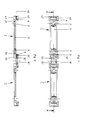
- a mounting bracket provided with openings for the passage of the fastening elements provided on the underside of the housing is used, on the free ends of which support webs are formed, which in turn are at a defined distance from the base at right angles to the support web to the outside have protruding and provided with an opening flange approaches, in each of which a molded on the bottom of the base body is inserted with a locking lug engaging behind the outer end wall of the opening.
- the mounting bracket with its support webs, the flange approaches and the openings can be designed so that the common housing dimensions can be snapped on without having to be drilled and dowelled again.
- the mounting bracket can also be designed as a double mounting bracket, on which, for example, two housings with a smaller receiving volume or a housing with a larger receiving volume can then be snapped on.
- Such housings such as junction boxes and the like are commercially available as standard components in standard sizes of 70 mm x 70 mm, 85 mm x 85 mm, 100 mm x 100 mm or 150 mm x 150 mm.
- the dimensions when using the double mounting bracket can be designed so that either two junction boxes of size 70 mm x 70 mm or a junction box of size 150 mm x 150 mm can be used without having to carry out major assembly work when converting from one box size to another would be necessary. Only the snap connection of the one can size is released on the mounting bracket and the snap connection is made with the other can size.
- the support webs of the mounting bracket engage with their free ends in a wall recess on the underside of the base body.
- the support webs can act as a protection against displacement of the housing on the mounting bracket.
- the mounting bracket is thickened in the area of the openings towards the base, and that the area of the thickening continues outwards into the supporting webs.
- a wall reinforcement is created in the area of the openings towards the base, via which the increased forces when fixing the mounting bracket via the fastening elements, e.g. Screws that can be attached to the base.
- spacers projecting outward from the base body underside are to be formed in the corner regions, and these are of a height correspond approximately to the distance of the flange attachments of the mounting bracket from the base. This measure prevents jamming of the housing on the mounting bracket and ensures a perfect locking connection of the housing on the mounting bracket.
- latching options for different housing sizes or a plurality of fastening brackets can be connected in one piece in their longitudinal plane in a fastening bracket by detachable connecting areas.
- the cable entry openings are designed in such a way that their circumferential limits are designed as individual threads running over the thickness of the housing side wall.
Landscapes
- Engineering & Computer Science (AREA)
- Architecture (AREA)
- Civil Engineering (AREA)
- Structural Engineering (AREA)
- Connection Or Junction Boxes (AREA)
Applications Claiming Priority (2)
| Application Number | Priority Date | Filing Date | Title |
|---|---|---|---|
| DE9215098U | 1992-11-06 | ||
| DE9215098U DE9215098U1 (de) | 1992-11-06 | 1992-11-06 | Gehäuse für elektrische Leitungen |
Publications (1)
| Publication Number | Publication Date |
|---|---|
| EP0596384A1 true EP0596384A1 (fr) | 1994-05-11 |
Family
ID=6885724
Family Applications (1)
| Application Number | Title | Priority Date | Filing Date |
|---|---|---|---|
| EP93117315A Withdrawn EP0596384A1 (fr) | 1992-11-06 | 1993-10-26 | Boîte pour conducteurs électriques |
Country Status (2)
| Country | Link |
|---|---|
| EP (1) | EP0596384A1 (fr) |
| DE (1) | DE9215098U1 (fr) |
Cited By (1)
| Publication number | Priority date | Publication date | Assignee | Title |
|---|---|---|---|---|
| RU2219633C2 (ru) * | 1998-09-25 | 2003-12-20 | ВИМАР С.п.А. | Система для закрепления электрических устройств в несущем корпусе |
Families Citing this family (1)
| Publication number | Priority date | Publication date | Assignee | Title |
|---|---|---|---|---|
| DE19711290C2 (de) * | 1997-03-18 | 2003-07-03 | Abb Patent Gmbh | Gehäuse, insbesondere für eine Installationsverteilung sowie Form, mit der das Gehäuse herstellbar ist |
Citations (5)
| Publication number | Priority date | Publication date | Assignee | Title |
|---|---|---|---|---|
| DE2625321A1 (de) * | 1975-06-06 | 1976-12-23 | Attema Kunststoffenind | Elektrische installationseinrichtung |
| DE2943112A1 (de) * | 1979-10-25 | 1981-05-07 | Brown, Boveri & Cie Ag, 6800 Mannheim | Befestigungssockel zur befestigung eines elektrischen schaltgeraetes oder dergleichen auf einer montageflaeche |
| DE3937371A1 (de) * | 1988-11-09 | 1990-05-10 | Bekaert Sa Nv | Leitungskanal |
| DE3908310A1 (de) * | 1989-03-14 | 1990-09-20 | Thyssen Polymer Gmbh | Installationskanal |
| DE3925010A1 (de) * | 1989-07-28 | 1991-01-31 | Giersiepen Gira Gmbh | Kabelkanal |
Family Cites Families (3)
| Publication number | Priority date | Publication date | Assignee | Title |
|---|---|---|---|---|
| AT303862B (de) * | 1970-03-06 | 1972-12-11 | Dietzel Gmbh | Abzweigkasten für elektrische Leitungen |
| DE8408806U1 (de) * | 1984-03-22 | 1984-07-12 | Norka Norddeutsche Kunststoff- und Elektro-Gesellschaft Stäcker & Co, 2817 Dörverden | Abzweigdose für elektrische Leitungen |
| DE3920964A1 (de) * | 1989-06-27 | 1991-01-10 | Rose Elektrotech Gmbh | Schutzgehaeuse fuer elektrische kabelverbindungen |
-
1992
- 1992-11-06 DE DE9215098U patent/DE9215098U1/de not_active Expired - Lifetime
-
1993
- 1993-10-26 EP EP93117315A patent/EP0596384A1/fr not_active Withdrawn
Patent Citations (5)
| Publication number | Priority date | Publication date | Assignee | Title |
|---|---|---|---|---|
| DE2625321A1 (de) * | 1975-06-06 | 1976-12-23 | Attema Kunststoffenind | Elektrische installationseinrichtung |
| DE2943112A1 (de) * | 1979-10-25 | 1981-05-07 | Brown, Boveri & Cie Ag, 6800 Mannheim | Befestigungssockel zur befestigung eines elektrischen schaltgeraetes oder dergleichen auf einer montageflaeche |
| DE3937371A1 (de) * | 1988-11-09 | 1990-05-10 | Bekaert Sa Nv | Leitungskanal |
| DE3908310A1 (de) * | 1989-03-14 | 1990-09-20 | Thyssen Polymer Gmbh | Installationskanal |
| DE3925010A1 (de) * | 1989-07-28 | 1991-01-31 | Giersiepen Gira Gmbh | Kabelkanal |
Cited By (1)
| Publication number | Priority date | Publication date | Assignee | Title |
|---|---|---|---|---|
| RU2219633C2 (ru) * | 1998-09-25 | 2003-12-20 | ВИМАР С.п.А. | Система для закрепления электрических устройств в несущем корпусе |
Also Published As
| Publication number | Publication date |
|---|---|
| DE9215098U1 (de) | 1992-12-17 |
Similar Documents
| Publication | Publication Date | Title |
|---|---|---|
| DE69404395T2 (de) | Anpassungsvorrichtung von einem elektrischen Mechanismus an einen elektrischen Kabelkanal | |
| DE3781001T2 (de) | Adaptertraeger fuer elektrogeraete. | |
| DE69610347T2 (de) | Winkelzubehörverbindungselement für Elektrokanal und Winkelzubehör dafür | |
| DE69924154T2 (de) | Gerätegehalter ,insbesondere für elektrisches gerät und damit ausgerüstetes gehäuse | |
| DE2121798C3 (de) | Einbauschalter mit abnehmbarer Deckplatte | |
| EP0596384A1 (fr) | Boîte pour conducteurs électriques | |
| DE69700859T2 (de) | Anordnung für einen elektrischen Abgangskasten | |
| EP0630091B1 (fr) | Armoire de distribution pour câbles de télécommunication | |
| DE102024100111A1 (de) | Zähler- und Verteilerschrank | |
| EP0355524B1 (fr) | Canalisation pour câble | |
| DE3300729A1 (de) | Installationsverteiler fuer elektrische einbaugeraete | |
| DE102006015317A1 (de) | Geräteeinbausatz zur Anordnung eines Gerätes in einer elektrischen Schaltanlage | |
| DE4290308C2 (de) | Kasten für automatische Sicherungen | |
| DE19845335B4 (de) | Geräteaufnahme für eine Unterflurgerätedose | |
| DE3638213C2 (fr) | ||
| DE69115367T2 (de) | Verbindungskiste für eine Kabelkanaleinrichtung | |
| DE19835837B4 (de) | Anordnung zur Halterung und Montage von elektrischen Installationsgeräten | |
| EP0802594B1 (fr) | Bandes d'obturation | |
| DE69810674T2 (de) | Verbesserte Kabelrinne | |
| DE19527013C2 (de) | Unterputzgeräte-Mehrfachkombination | |
| EP1191656A2 (fr) | Une réception d'appareil pour boítier pour appareillage installé sous plancher | |
| DE20019792U1 (de) | Steckverbinder-Gehäuse mit Kodiereinrichtung | |
| EP0545124A1 (fr) | Dispositif de montage pour un appareil auxiliaire dans une ouverture prédécoupée d'un véhicule automobile | |
| EP1317041B1 (fr) | Boitier d'appareil pour dispositif d'installation électrique | |
| DE102009009500A1 (de) | Gehäuse |
Legal Events
| Date | Code | Title | Description |
|---|---|---|---|
| PUAI | Public reference made under article 153(3) epc to a published international application that has entered the european phase |
Free format text: ORIGINAL CODE: 0009012 |
|
| 17P | Request for examination filed |
Effective date: 19940208 |
|
| AK | Designated contracting states |
Kind code of ref document: A1 Designated state(s): AT BE CH DE DK ES FR GB GR IE IT LI LU NL PT SE |
|
| 17Q | First examination report despatched |
Effective date: 19950428 |
|
| STAA | Information on the status of an ep patent application or granted ep patent |
Free format text: STATUS: THE APPLICATION HAS BEEN WITHDRAWN |
|
| RIN1 | Information on inventor provided before grant (corrected) |
Inventor name: STRICKSTROCK, THEO,C/O REHAU AG + CO |
|
| 18W | Application withdrawn |
Withdrawal date: 19950616 |
|
| R18W | Application withdrawn (corrected) |
Effective date: 19950616 |