EP0596480A1 - Cylindre de fermeture et procédé pour fabriquer ce cylindre de fermeture - Google Patents
Cylindre de fermeture et procédé pour fabriquer ce cylindre de fermeture Download PDFInfo
- Publication number
- EP0596480A1 EP0596480A1 EP93117831A EP93117831A EP0596480A1 EP 0596480 A1 EP0596480 A1 EP 0596480A1 EP 93117831 A EP93117831 A EP 93117831A EP 93117831 A EP93117831 A EP 93117831A EP 0596480 A1 EP0596480 A1 EP 0596480A1
- Authority
- EP
- European Patent Office
- Prior art keywords
- housing
- housing pin
- lock cylinder
- core
- pin bore
- Prior art date
- Legal status (The legal status is an assumption and is not a legal conclusion. Google has not performed a legal analysis and makes no representation as to the accuracy of the status listed.)
- Granted
Links
- 238000000034 method Methods 0.000 title claims description 11
- 238000005553 drilling Methods 0.000 claims abstract description 6
- 238000003780 insertion Methods 0.000 claims description 13
- 230000037431 insertion Effects 0.000 claims description 13
- 230000006835 compression Effects 0.000 claims description 12
- 238000007906 compression Methods 0.000 claims description 12
- 239000000945 filler Substances 0.000 claims description 12
- 238000004519 manufacturing process Methods 0.000 claims description 9
- 238000000926 separation method Methods 0.000 claims description 9
- 238000004381 surface treatment Methods 0.000 claims description 3
- 238000005192 partition Methods 0.000 claims 1
- 238000010276 construction Methods 0.000 description 5
- 238000003825 pressing Methods 0.000 description 3
- 238000005516 engineering process Methods 0.000 description 2
- 230000001771 impaired effect Effects 0.000 description 2
- 238000003754 machining Methods 0.000 description 2
- 230000002093 peripheral effect Effects 0.000 description 2
- 239000013589 supplement Substances 0.000 description 2
- CWYNVVGOOAEACU-UHFFFAOYSA-N Fe2+ Chemical compound [Fe+2] CWYNVVGOOAEACU-UHFFFAOYSA-N 0.000 description 1
- 229910000831 Steel Inorganic materials 0.000 description 1
- 230000002411 adverse Effects 0.000 description 1
- 238000013459 approach Methods 0.000 description 1
- 239000003086 colorant Substances 0.000 description 1
- 230000000295 complement effect Effects 0.000 description 1
- 239000000356 contaminant Substances 0.000 description 1
- 230000000694 effects Effects 0.000 description 1
- 239000012535 impurity Substances 0.000 description 1
- 230000014759 maintenance of location Effects 0.000 description 1
- 239000002184 metal Substances 0.000 description 1
- 238000012856 packing Methods 0.000 description 1
- 230000035515 penetration Effects 0.000 description 1
- 238000012805 post-processing Methods 0.000 description 1
- 239000010959 steel Substances 0.000 description 1
- 230000007704 transition Effects 0.000 description 1
Images

Classifications
-
- E—FIXED CONSTRUCTIONS
- E05—LOCKS; KEYS; WINDOW OR DOOR FITTINGS; SAFES
- E05B—LOCKS; ACCESSORIES THEREFOR; HANDCUFFS
- E05B27/00—Cylinder locks or other locks with tumbler pins or balls that are set by pushing the key in
- E05B27/0003—Details
- E05B27/0014—Stators
Definitions
- the invention relates to a locking cylinder comprising a locking cylinder housing with an outer surface and a core receiving bore, a locking cylinder core rotatably received in this core receiving bore with a key insertion slot for receiving a key, and at least one pair of locking pins, said locking pin pair being a core pin bore guided in a core pin bore of the locking cylinder core and a core pin bore of the lock cylinder housing guided housing pin, which pins are aligned with one another in a basic position of the lock cylinder housing relative to the lock cylinder housing and, with the key adapted to the lock secret, being adjusted by pretensioning means in such a way that a mutually facing end parts of the core pin and the housing pin lie in the cylindrical separating surface between the core and the receiving hole on the core Lock cylinder core lies and where the Genzo Usestattbohrung cuts a surface area of the outer surface of the lock cylinder housing and is closed by a closure means.
- Such a lock cylinder is known for example from German patent 33 38 713.
- a plurality of tumbler pin pairs are arranged one behind the other in the direction of the longitudinal axis of the locking cylinder, the housing pin bores being accommodated in the web part of a so-called cock profile of the locking cylinder housing.
- the closure means for closing the housing pin bores are formed by grooved pins, which in the outer ends of the housing pin bores, i.e. the ends of the housing pin bores opening in the area of the sack bottom surface of the profile web are pressed in.
- the ends of the notch pins in the area of the bag bottom surface are machined so that they completely complement the cylindrical bag bottom surface in accordance with their cylindrical shape.
- the closure means has a convex end surface which is rotationally symmetrical with respect to an axis of the housing pin bore and seen from the outer space surrounding the outer surface, the end surface of which is orthogonal to the axis of the housing pin bore
- Large cross-section lies on its entire circumference within the housing pin bore and the apex of which is preferably at or at a small distance within a virtual partial area of the respective surface area delimited by the housing pin bore, which corresponds to a partial area of the surface area removed when the hole is drilled.
- the remaining ring recesses which increase in depth from the apex area to the circumferential surface of the housing pin bores, are so small that there is no fear of chips and similar impurities getting caught to a greater extent.
- the locking cylinder designed according to the invention feels almost as smooth and touch-friendly as a locking cylinder in which the locking means are smoothly adapted to the respective surface area.
- the end surface can be a spherical end surface with a diameter that approximately corresponds to the diameter of the housing pin bore.
- the closure parts can be produced in such a quality and in particular such a hardness that they are not damaged when they are introduced into the housing pin bores, however this is carried out, and therefore their appearance is not impaired.
- the closure elements can be polished at the ends, for example, or otherwise surface-treated, so that they fit well into the surface appearance of conventional galvanized or lacquered locking cylinders, whereby interesting effects can still be achieved through different colors, different glosses or other different surface designs.
- the fastening of the closure means in the housing pin bores is preferably carried out by pressing in, the diameter of the closure means being matched to the diameter of the housing pin bores in such a way that pressing in is achieved on the one hand without visible deformation of the respective surface area, but on the other hand an immovable retention of the closure means in the housing pin bores is guaranteed.
- lock cylinder housings are usually made of a non-ferrous metal, steel parts can be used as the closure means, which can be mass-produced cheaply.
- the proposal for the invention is particularly applicable when the surface area into which the housing pin bores open, is formed by a cylindrical surface, the surface lines of which run parallel to the axis of the core receiving bores. This applies both to round cylinders and to the popular locking cylinders with Hahn profile, in which the housing pin bores cut the sack bottom surface of the profile web of the Hahn profile.
- the closure means is formed by a ball.
- the advantage of this embodiment is that the automatic feeding in an automatic manufacturing machine can be carried out using balls without complicated orientation means.
- balls as a closing means is to be regarded as unusual because when using balls there is no freedom of variation with regard to the axial depth of the closing means ball, in order to be able to adapt to different cylinder shapes, different preloading means and different housing pin dimensions.
- this has surprisingly proven to be harmless because there is the possibility of varying the respective free length of the housing pin bore by introducing fillers into the housing pin bore, so that the prestressing means can then be supported on such fillers if necessary.
- balls or cylinder sections can be used as packing.
- the closure means may be formed by a rod which has the rotationally symmetrical convex end face at at least one end, preferably both.
- the assembly technology is complicated by such a measure compared to a ball, however, so that this option will only be used in special situations, for example when special profiles of the spherical end faces are to be selected.
- an annular shoulder is also provided at the transition from the rod to the convex end face. In this way, the maximum cross section of the convex end surface can be smaller than the cross section of the cylindrical section of the rod-shaped closure means.
- the biasing means can be formed by helical compression springs. It is advantageous if the helical compression spring for positioning has an enveloping surface at least over part of its length, the diameter of which corresponds at least approximately to the inside diameter of the housing pin bore. To prevent the helical compression spring from incorrectly adjusting or jamming against a convex surface of the closure means in the gap formed between the circumferential surface of the housing pin bore and the convex end surface, it may be advantageous if the helical compression spring is at least at the end in contact with the spherical surface has a tapered section.
- the invention further relates to a method for producing a locking cylinder, said locking cylinder comprising a locking cylinder housing with an outer surface and a core receiving bore, a locking cylinder core rotatably received in said core receiving bore with a key insertion slot for receiving a key and at least one pair of locking pins, said locking pin pair one in a core pin bore Locking cylinder core-guided core pin and a housing pin guided in a housing pin bore of the locking cylinder housing, which pins are aligned with one another in a basic position of the locking cylinder core with respect to the locking cylinder housing and, when the key, which is adapted to the locking secret, is inserted, are set by pretensioning means such that a separating end pin and separating end pin parts are located between the core pin in the cylindrical interface between the core receptacle bo and the locking cylinder core, and wherein the housing pin bore cuts an area of the outer surface of the locking cylinder housing and is closed by closure means, this method comprises a drilling operation starting from the surface area cut through
- a closure body be inserted as a closure means into the housing pin bore, which at least at its end trailing during insertion has an end surface that is rotationally symmetrical with respect to an axis of the housing pin bore and that is convex as seen from the outer space surrounding the outer surface, whose largest cross-section orthogonal to the axis of the housing pin bore enters the housing pin bore over its entire circumference, while the apex is preferably placed at or at a small distance within a virtual partial area of the respective surface area delimited by the housing pin bore, which part of the surface area is removed when the bore is drilled corresponds.
- the closure body can be fixed in the housing pin bore by a press fit.
- the closure body can be inserted through an insertion surface of an insertion tool which determines the insertion depth against the respective surface area.
- This insertion surface can press in several closure means at the same time, so that their uniform positioning is ensured.
- closure body is inserted into the housing pin bore after the housing pin and possibly the pretensioning means and / or a filler body have been inserted through the outer end of the housing pin bore associated with the surface area.
- the housing pin and possibly a filler and / or a pretensioner may be inserted into the housing pin bore from the core pin bore after the outer end of the housing pin bore facing the surface area has been closed by inserting the closure body.
- the decision about which of the two options is chosen also depends in particular on the existing manufacturing facilities.
- the resulting bore is preferably only made up to the intersection with the core pin bore, so that the area of the cylinder housing diametrically opposite the housing pin bore is not cut and therefore does not have to be closed again.
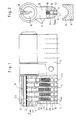
- the lock cylinder housing of a double lock cylinder is generally designated 10.
- This lock cylinder housing has a so-called Hahn profile with a profile web 12, the bag bottom surface of which is designated 14.
- the lock cylinder 10 also has a core bore 16 which receives a lock cylinder core 18 with a key insertion slot 20.
- This tumbler pin pair 22 consists of a core pin 22a and a housing pin 22b.
- the core pin 22a is received in a core pin bore 24a of the lock cylinder core 18, while the housing pin 22b is received by a housing pin bore 24b of the lock cylinder housing 10.
- the core pin 22a and the housing pin 22b are aligned with one another.
- the separation point 22c between the core pin 22a and the housing pin 22b is, when a key adapted for a locking secret is inserted, in the separation surface 28, which is defined by the inner peripheral surface of the core bore 16 and the outer peripheral surface of the lock cylinder core 18. If the separation points of all the pairs of pin cylinders lie in the separation surface 28, the lock cylinder core can be rotated by means of the key.
- the housing pin bore 24b is drilled from the bag bottom surface 14 into the lock cylinder housing 10 until it intersects with the core bore 16.
- the lower end of the housing pin bore 24b is closed by a locking ball 30 with an end surface 30a which is pressed into the housing pin bore 24b with a slight oversize.
- the locking balls 30 of the individual housing pin pairs can be pressed in by a common tool 32, which is shown in FIG.
- This housing has a thrust surface 34 which is precisely adapted to the sack bottom surface 14 and which, when the tool 32 approaches the sack bottom surface 14, bears against it and thereby brings the balls 30 into a position in which their apex regions S pointing downward each have a virtual surface V lie, which complements the bag bottom surface 14 with a corresponding curvature.
- the upper and lower ends of the helical compression spring 38 are wound closer than the middle section, so that these end sections find a defined contact with the filling ball 36 and the lower end of the housing pin 22b.
- the housing pin pairs can have different shapes as indicated in the figure.
- the separating point 22c which with the key fitted to the secret, is adapted must lie in the separating surface 28, does not necessarily have to be formed by the facing ends of the pins 22a and 22b themselves, but can also be formed by one of these pins and an intermediate plate which can be used in varying thicknesses for the closure variation.
- the separation point can also be formed between two adjacent intermediate plates (not shown).
- Lock cylinder core 18 and lock cylinder housing are manufactured separately.
- the lock cylinder core is provided with the bores 24a.
- the housing pin bores are drilled from the sack bottom surface 14 until the respective drilling instrument enters the core bore 16.
- the locking cylinder core 18 is then fitted with the core pins 22a and inserted into the core bore 16, wherein it is rotated relative to the basic position according to FIG. 1.
- the housing pin 22b, the helical compression spring 38, the filling ball 36 and the closure ball 30 can be inserted one after the other through the housing bore 24b.
- the housing pin 22b enters the core pin bore 24a.
- FIGS. 3 and 4 differs from that according to FIGS. 1 and 2 only in that 36 filler pins 136 are provided instead of the filler balls.
- the length of the cylindrical filler pins can be predetermined in accordance with the respective space requirement.
- locking pins can also be used (not shown in the drawing) which have a convexly curved, in particular spherical, end face at at least one end. Such locking pins are preferably made at both ends with identical convex surfaces in order to simplify the automatic feeding.
Landscapes
- Lock And Its Accessories (AREA)
- Pistons, Piston Rings, And Cylinders (AREA)
- Fluid-Damping Devices (AREA)
- Cylinder Crankcases Of Internal Combustion Engines (AREA)
- Pens And Brushes (AREA)
- Taps Or Cocks (AREA)
- Nitrogen Condensed Heterocyclic Rings (AREA)
- Plural Heterocyclic Compounds (AREA)
- Forklifts And Lifting Vehicles (AREA)
- Vehicle Body Suspensions (AREA)
- Actuator (AREA)
- Refuge Islands, Traffic Blockers, Or Guard Fence (AREA)
- Bending Of Plates, Rods, And Pipes (AREA)
- Diaphragms For Electromechanical Transducers (AREA)
- Automatic Assembly (AREA)
Applications Claiming Priority (2)
| Application Number | Priority Date | Filing Date | Title |
|---|---|---|---|
| DE4237565A DE4237565C2 (de) | 1992-11-06 | 1992-11-06 | Schließzylinder und Verfahren zur Herstellung des Schließzylinders |
| DE4237565 | 1992-11-06 |
Publications (2)
| Publication Number | Publication Date |
|---|---|
| EP0596480A1 true EP0596480A1 (fr) | 1994-05-11 |
| EP0596480B1 EP0596480B1 (fr) | 1996-02-21 |
Family
ID=6472305
Family Applications (1)
| Application Number | Title | Priority Date | Filing Date |
|---|---|---|---|
| EP93117831A Expired - Lifetime EP0596480B1 (fr) | 1992-11-06 | 1993-11-03 | Cylindre de fermeture et procédé pour fabriquer ce cylindre de fermeture |
Country Status (9)
| Country | Link |
|---|---|
| EP (1) | EP0596480B1 (fr) |
| AT (1) | ATE134413T1 (fr) |
| CZ (1) | CZ289740B6 (fr) |
| DE (2) | DE4237565C2 (fr) |
| ES (1) | ES2087634T3 (fr) |
| FI (1) | FI934892A7 (fr) |
| NO (1) | NO933925L (fr) |
| PL (1) | PL172701B1 (fr) |
| SK (1) | SK280825B6 (fr) |
Cited By (2)
| Publication number | Priority date | Publication date | Assignee | Title |
|---|---|---|---|---|
| WO2012005714A1 (fr) * | 2010-07-08 | 2012-01-12 | Streltsov Sergey Nikolayevich | Tête secrète pour dispositif de fermeture mécanique |
| CN109667478A (zh) * | 2019-01-21 | 2019-04-23 | 朱金勇 | 一种新型的葫芦锁胆机器制作工艺 |
Families Citing this family (1)
| Publication number | Priority date | Publication date | Assignee | Title |
|---|---|---|---|---|
| DE102010012342B4 (de) * | 2010-03-23 | 2020-03-26 | Airbus Operations Gmbh | Versteifungsbauteil und Verfahren sowie Kammwerkzeug |
Citations (3)
| Publication number | Priority date | Publication date | Assignee | Title |
|---|---|---|---|---|
| EP0226252A2 (fr) * | 1985-12-19 | 1987-06-24 | RIELDA SERRATURE s.r.l. | Serrure à cylindre avec clé interchangeable |
| EP0364660A2 (fr) * | 1988-10-21 | 1990-04-25 | Erich Mundhenke | Serrure cylindrique |
| EP0449177A2 (fr) * | 1990-03-27 | 1991-10-02 | Aug. Winkhaus GmbH & Co. KG | Barillet |
Family Cites Families (1)
| Publication number | Priority date | Publication date | Assignee | Title |
|---|---|---|---|---|
| GB2128670B (en) * | 1982-10-25 | 1985-10-23 | Talleres Escoriaza Sa | Cylinder lock |
-
1992
- 1992-11-06 DE DE4237565A patent/DE4237565C2/de not_active Expired - Fee Related
-
1993
- 1993-10-27 SK SK1200-93A patent/SK280825B6/sk unknown
- 1993-10-29 NO NO933925A patent/NO933925L/no not_active Application Discontinuation
- 1993-11-03 ES ES93117831T patent/ES2087634T3/es not_active Expired - Lifetime
- 1993-11-03 DE DE59301678T patent/DE59301678D1/de not_active Expired - Fee Related
- 1993-11-03 EP EP93117831A patent/EP0596480B1/fr not_active Expired - Lifetime
- 1993-11-03 AT AT93117831T patent/ATE134413T1/de not_active IP Right Cessation
- 1993-11-04 PL PL93300936A patent/PL172701B1/pl not_active IP Right Cessation
- 1993-11-04 CZ CZ19932350A patent/CZ289740B6/cs not_active IP Right Cessation
- 1993-11-05 FI FI934892A patent/FI934892A7/fi unknown
Patent Citations (3)
| Publication number | Priority date | Publication date | Assignee | Title |
|---|---|---|---|---|
| EP0226252A2 (fr) * | 1985-12-19 | 1987-06-24 | RIELDA SERRATURE s.r.l. | Serrure à cylindre avec clé interchangeable |
| EP0364660A2 (fr) * | 1988-10-21 | 1990-04-25 | Erich Mundhenke | Serrure cylindrique |
| EP0449177A2 (fr) * | 1990-03-27 | 1991-10-02 | Aug. Winkhaus GmbH & Co. KG | Barillet |
Cited By (3)
| Publication number | Priority date | Publication date | Assignee | Title |
|---|---|---|---|---|
| WO2012005714A1 (fr) * | 2010-07-08 | 2012-01-12 | Streltsov Sergey Nikolayevich | Tête secrète pour dispositif de fermeture mécanique |
| RU2462572C1 (ru) * | 2010-07-08 | 2012-09-27 | Сергей Николаевич Стрельцов | Секретная головка механического запирающего устройства |
| CN109667478A (zh) * | 2019-01-21 | 2019-04-23 | 朱金勇 | 一种新型的葫芦锁胆机器制作工艺 |
Also Published As
| Publication number | Publication date |
|---|---|
| ATE134413T1 (de) | 1996-03-15 |
| SK280825B6 (sk) | 2000-08-14 |
| DE4237565C2 (de) | 1995-04-06 |
| DE59301678D1 (de) | 1996-03-28 |
| EP0596480B1 (fr) | 1996-02-21 |
| ES2087634T3 (es) | 1996-07-16 |
| NO933925D0 (no) | 1993-10-29 |
| NO933925L (no) | 1994-05-09 |
| FI934892A7 (fi) | 1994-05-07 |
| SK120093A3 (en) | 1994-08-10 |
| CZ289740B6 (cs) | 2002-03-13 |
| PL300936A1 (en) | 1994-05-16 |
| FI934892A0 (fi) | 1993-11-05 |
| CZ235093A3 (en) | 1994-06-15 |
| DE4237565A1 (de) | 1994-05-11 |
| PL172701B1 (pl) | 1997-11-28 |
Similar Documents
| Publication | Publication Date | Title |
|---|---|---|
| AT392818B (de) | Schliesssystem | |
| DE69111409T2 (de) | Zylinderschlösser, mit auswechselbaren Zylindern. | |
| DE3503660A1 (de) | Schliessvorrichtung mit schliesszylinder und flachschluessel | |
| EP3153648B1 (fr) | Cadenas | |
| DE2533494C3 (de) | SchlieBzylinder mit Stiftzuhaltungen und Schlüssel | |
| DE3338713C2 (de) | Schließzylinder | |
| DE2815585C2 (de) | Schließzylinder | |
| EP1333136B1 (fr) | Serrure cylindrique | |
| EP0596480B1 (fr) | Cylindre de fermeture et procédé pour fabriquer ce cylindre de fermeture | |
| DE2700350A1 (de) | Aufbruchsichere schliessvorrichtung | |
| DE2038039A1 (de) | Schließzylinder | |
| EP0625624A1 (fr) | Serrure cylindrique | |
| AT403607B (de) | Schliesseinrichtung mit einem zylinderschloss und einem wendeflachschlüssel | |
| EP0307347B1 (fr) | Dispositif protecteur pour serrure | |
| AT523792B1 (de) | Flachschlüssel für ein Zylinderschloss | |
| EP0620340B1 (fr) | Combinaison d'une clé plate et d'une serrure cylindrique | |
| EP0191342B1 (fr) | Verrou cylindrique à éléments préassemblés | |
| EP1333135B1 (fr) | Serrure cylindrique | |
| DE9307547U1 (de) | Schließzylinder | |
| EP1057953B1 (fr) | Serrure cylindrique et clé correspondante | |
| EP1785558B1 (fr) | Serrure, en particulier pour coffre-fort | |
| DE2622961A1 (de) | Schloss mit mindestens einem beim einfuehren des schluessels ausweichenden schliessorgan und verfahren zur erstellung dieses schlosses | |
| EP0430185A2 (fr) | Dispositif de fixation de carré de poignée pour l'actionnement d'une porte ou similaire | |
| DE19745834A1 (de) | Wendeschlüssel | |
| EP1132551B1 (fr) | Dispositif de verrouillage avec clé réversible |
Legal Events
| Date | Code | Title | Description |
|---|---|---|---|
| PUAI | Public reference made under article 153(3) epc to a published international application that has entered the european phase |
Free format text: ORIGINAL CODE: 0009012 |
|
| AK | Designated contracting states |
Kind code of ref document: A1 Designated state(s): AT BE CH DE DK ES FR GB GR IE IT LI LU MC NL PT SE |
|
| 17P | Request for examination filed |
Effective date: 19940520 |
|
| 17Q | First examination report despatched |
Effective date: 19950523 |
|
| GRAA | (expected) grant |
Free format text: ORIGINAL CODE: 0009210 |
|
| AK | Designated contracting states |
Kind code of ref document: B1 Designated state(s): AT BE CH DE DK ES FR GB GR IE IT LI LU MC NL PT SE |
|
| PG25 | Lapsed in a contracting state [announced via postgrant information from national office to epo] |
Ref country code: GR Free format text: LAPSE BECAUSE OF FAILURE TO SUBMIT A TRANSLATION OF THE DESCRIPTION OR TO PAY THE FEE WITHIN THE PRESCRIBED TIME-LIMIT Effective date: 19960221 Ref country code: DK Effective date: 19960221 |
|
| REF | Corresponds to: |
Ref document number: 134413 Country of ref document: AT Date of ref document: 19960315 Kind code of ref document: T |
|
| ITF | It: translation for a ep patent filed | ||
| REG | Reference to a national code |
Ref country code: IE Ref legal event code: FG4D Free format text: 67306 |
|
| REF | Corresponds to: |
Ref document number: 59301678 Country of ref document: DE Date of ref document: 19960328 |
|
| REG | Reference to a national code |
Ref country code: CH Ref legal event code: NV Representative=s name: E. BLUM & CO. PATENTANWAELTE |
|
| GBT | Gb: translation of ep patent filed (gb section 77(6)(a)/1977) |
Effective date: 19960328 |
|
| PG25 | Lapsed in a contracting state [announced via postgrant information from national office to epo] |
Ref country code: SE Effective date: 19960521 Ref country code: PT Effective date: 19960521 |
|
| REG | Reference to a national code |
Ref country code: ES Ref legal event code: BA2A Ref document number: 2087634 Country of ref document: ES Kind code of ref document: T3 |
|
| ET | Fr: translation filed | ||
| REG | Reference to a national code |
Ref country code: ES Ref legal event code: FG2A Ref document number: 2087634 Country of ref document: ES Kind code of ref document: T3 |
|
| REG | Reference to a national code |
Ref country code: IE Ref legal event code: FD4D Ref document number: 67306 Country of ref document: IE |
|
| PG25 | Lapsed in a contracting state [announced via postgrant information from national office to epo] |
Ref country code: IE Free format text: LAPSE BECAUSE OF NON-PAYMENT OF DUE FEES Effective date: 19961106 |
|
| PG25 | Lapsed in a contracting state [announced via postgrant information from national office to epo] |
Ref country code: LU Free format text: LAPSE BECAUSE OF NON-PAYMENT OF DUE FEES Effective date: 19961130 |
|
| PLBE | No opposition filed within time limit |
Free format text: ORIGINAL CODE: 0009261 |
|
| STAA | Information on the status of an ep patent application or granted ep patent |
Free format text: STATUS: NO OPPOSITION FILED WITHIN TIME LIMIT |
|
| 26N | No opposition filed | ||
| PG25 | Lapsed in a contracting state [announced via postgrant information from national office to epo] |
Ref country code: MC Effective date: 19970531 |
|
| PGFP | Annual fee paid to national office [announced via postgrant information from national office to epo] |
Ref country code: ES Payment date: 20011114 Year of fee payment: 9 |
|
| PGFP | Annual fee paid to national office [announced via postgrant information from national office to epo] |
Ref country code: BE Payment date: 20011127 Year of fee payment: 9 |
|
| PGFP | Annual fee paid to national office [announced via postgrant information from national office to epo] |
Ref country code: CH Payment date: 20011207 Year of fee payment: 9 |
|
| REG | Reference to a national code |
Ref country code: GB Ref legal event code: IF02 |
|
| PG25 | Lapsed in a contracting state [announced via postgrant information from national office to epo] |
Ref country code: ES Free format text: LAPSE BECAUSE OF NON-PAYMENT OF DUE FEES Effective date: 20021104 |
|
| PG25 | Lapsed in a contracting state [announced via postgrant information from national office to epo] |
Ref country code: LI Free format text: LAPSE BECAUSE OF NON-PAYMENT OF DUE FEES Effective date: 20021130 Ref country code: CH Free format text: LAPSE BECAUSE OF NON-PAYMENT OF DUE FEES Effective date: 20021130 Ref country code: BE Free format text: LAPSE BECAUSE OF NON-PAYMENT OF DUE FEES Effective date: 20021130 |
|
| BERE | Be: lapsed |
Owner name: AUG. *WINKHAUS G.M.B.H. & CO. K.G. Effective date: 20021130 |
|
| REG | Reference to a national code |
Ref country code: CH Ref legal event code: PL |
|
| REG | Reference to a national code |
Ref country code: ES Ref legal event code: FD2A Effective date: 20031213 |
|
| PGFP | Annual fee paid to national office [announced via postgrant information from national office to epo] |
Ref country code: GB Payment date: 20061017 Year of fee payment: 14 |
|
| PGFP | Annual fee paid to national office [announced via postgrant information from national office to epo] |
Ref country code: FR Payment date: 20061127 Year of fee payment: 14 |
|
| PGFP | Annual fee paid to national office [announced via postgrant information from national office to epo] |
Ref country code: NL Payment date: 20061130 Year of fee payment: 14 Ref country code: IT Payment date: 20061130 Year of fee payment: 14 |
|
| GBPC | Gb: european patent ceased through non-payment of renewal fee |
Effective date: 20071103 |
|
| NLV4 | Nl: lapsed or anulled due to non-payment of the annual fee |
Effective date: 20080601 |
|
| PG25 | Lapsed in a contracting state [announced via postgrant information from national office to epo] |
Ref country code: NL Free format text: LAPSE BECAUSE OF NON-PAYMENT OF DUE FEES Effective date: 20080601 |
|
| REG | Reference to a national code |
Ref country code: FR Ref legal event code: ST Effective date: 20080930 |
|
| PG25 | Lapsed in a contracting state [announced via postgrant information from national office to epo] |
Ref country code: GB Free format text: LAPSE BECAUSE OF NON-PAYMENT OF DUE FEES Effective date: 20071103 |
|
| PGFP | Annual fee paid to national office [announced via postgrant information from national office to epo] |
Ref country code: DE Payment date: 20081210 Year of fee payment: 16 |
|
| PGFP | Annual fee paid to national office [announced via postgrant information from national office to epo] |
Ref country code: AT Payment date: 20081118 Year of fee payment: 16 |
|
| PG25 | Lapsed in a contracting state [announced via postgrant information from national office to epo] |
Ref country code: FR Free format text: LAPSE BECAUSE OF NON-PAYMENT OF DUE FEES Effective date: 20071130 |
|
| PG25 | Lapsed in a contracting state [announced via postgrant information from national office to epo] |
Ref country code: IT Free format text: LAPSE BECAUSE OF NON-PAYMENT OF DUE FEES Effective date: 20071103 |
|
| PG25 | Lapsed in a contracting state [announced via postgrant information from national office to epo] |
Ref country code: AT Free format text: LAPSE BECAUSE OF NON-PAYMENT OF DUE FEES Effective date: 20091103 |
|
| PG25 | Lapsed in a contracting state [announced via postgrant information from national office to epo] |
Ref country code: DE Free format text: LAPSE BECAUSE OF NON-PAYMENT OF DUE FEES Effective date: 20100601 |