EP0596538A1 - Echangeur de chaleur comportant un dispositif pour distribuer des billes d'acier - Google Patents
Echangeur de chaleur comportant un dispositif pour distribuer des billes d'acier Download PDFInfo
- Publication number
- EP0596538A1 EP0596538A1 EP93118919A EP93118919A EP0596538A1 EP 0596538 A1 EP0596538 A1 EP 0596538A1 EP 93118919 A EP93118919 A EP 93118919A EP 93118919 A EP93118919 A EP 93118919A EP 0596538 A1 EP0596538 A1 EP 0596538A1
- Authority
- EP
- European Patent Office
- Prior art keywords
- steel ball
- heat transfer
- heat
- scatterer
- exchanger
- Prior art date
- Legal status (The legal status is an assumption and is not a legal conclusion. Google has not performed a legal analysis and makes no representation as to the accuracy of the status listed.)
- Granted
Links
- 229910000831 Steel Inorganic materials 0.000 title claims abstract description 100
- 239000010959 steel Substances 0.000 title claims abstract description 100
- 239000004071 soot Substances 0.000 claims abstract description 18
- 239000000428 dust Substances 0.000 claims description 9
- 239000000463 material Substances 0.000 claims description 6
- 239000007769 metal material Substances 0.000 claims description 2
- 230000001012 protector Effects 0.000 description 13
- 230000000694 effects Effects 0.000 description 3
- 238000010586 diagram Methods 0.000 description 2
- 230000002035 prolonged effect Effects 0.000 description 2
- 230000001105 regulatory effect Effects 0.000 description 2
- 230000001133 acceleration Effects 0.000 description 1
- 230000000052 comparative effect Effects 0.000 description 1
- 238000011109 contamination Methods 0.000 description 1
- 230000000593 degrading effect Effects 0.000 description 1
- 230000002542 deteriorative effect Effects 0.000 description 1
- 230000005484 gravity Effects 0.000 description 1
- 238000000034 method Methods 0.000 description 1
- 238000000790 scattering method Methods 0.000 description 1
- 238000011144 upstream manufacturing Methods 0.000 description 1
Images



Classifications
-
- F—MECHANICAL ENGINEERING; LIGHTING; HEATING; WEAPONS; BLASTING
- F28—HEAT EXCHANGE IN GENERAL
- F28G—CLEANING OF INTERNAL OR EXTERNAL SURFACES OF HEAT-EXCHANGE OR HEAT-TRANSFER CONDUITS, e.g. WATER TUBES OR BOILERS
- F28G1/00—Non-rotary, e.g. reciprocated, appliances
- F28G1/12—Fluid-propelled scrapers, bullets, or like solid bodies
Definitions
- the present invention relates to a heat-exchanger provided with a steel ball scatterer.
- a heat-exchanger having a steel ball scattering device assembled therein has heretofore come into practical use.
- Fig. 1 is a general vertical cross-section view showing one example of such heat-exchanger in the prior art
- Fig. 2 is a perspective view partly cut away of the same heat-exchanger.
- reference numeral 1 designates a main body casing of a heat-exchanger, in which heat transfer tube groups 2 are disposed and steel ball scatterers 3 are provided above (on the upstream of) the heat transfer tube groups.
- steel ball scatterers 3 To these steel ball scatterers 3 are fed steel balls from a steel ball feeder 4. The steel balls scattered by the steel ball scatterers 3 would fall while removing soot or the like adhered to the heat transfer groups 2. Then they would be returned to the above-mentioned steel ball feeder 4 by a steel ball conveyor 5.
- Reference numeral 6 designates a gas inlet
- numeral 7 designates a gas outlet
- the gas inlet 6 is provided at one end of the heat-exchanger main body 1 above the steel ball scatterers 3
- the gas outlet 7 is provided at one side portion of the heat-exchanger main body 1 lower than the heat transfer tube groups 2.
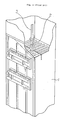
- Fig. 3 is a perspective view showing one example of the steel ball scatterer 3, and in this figure, reference numeral 3a designates a steel ball feed pipe having a square cross-section and numeral 3b designates a scattering plate, whose upper surface configuration forms a part of a spherical surface.
- the number of steel ball scatterers 3 disposed within the heat-exchanger is determined depending upon a projection cross-section area of the heat transfer tube groups and a steel ball scattering area of one steel ball scatterer, and if the steel ball scattering area of one steel ball scatterer is broad, the number of the disposed steel ball scatterers can be made small.
- a scattering rate and a scattering method of steel balls are regulated depending upon the amount of soot or the like adhered to the heat transfer tubes. More particularly, in the case where the adhered amount is much (an adhering rate is large), unless steel balls are continuously scattered at a large rate, the adhered amount of soot or the like would increase and a predetermined heat transfer performance could not be maintained. On the other hand, in the case where the adhered amount is little, a heat transfer performance could be maintained even if the scattering rate is made small or even if intermittent scattering at a long time interval is effected.
- a scattering range and a scattering height of steel balls of a steel ball scatterer are, in
- a scattering range as well as a scattering height are related to the velocity (v o ) of a steel ball when it collides with a scattering plate.
- This collision velocity (v o ) is proportional to a square root of a height of fall in the case of natural falling.
- FIG. 4 is a longitudinal cross-section view showing a part of a finned heat transfer tube 8
- Fig. 5 is a transverse cross-section view of the same.
- a top portion of a fin 8b mounted to a pipe 8a is damaged and deformed by collision with a falling steel ball as shown at 8c in Fig. 4. This damage depends upon a colliding velocity of a steel ball, and the larger the colliding velocity is, the greater is the damage.
- a colliding velocity of a steel ball against a fin depends upon a height of natural falling of a steel ball as described above, and it also relates to a scattering height of a steel ball. Accordingly, as a scattering range of steel balls by a steel ball scatterer is broadened, a scattering height would become higher and damage of a fin would become larger. However, if it is tried to prevent damage of fins by sacrificing a scattering range of steel balls, a number of disposed steel scatterers must be remarkably increased, and this is practically impossible.
- a heat-exchanger provided with a steel ball scatterer, wherein a group of heat transfer tubes and a steel ball scatterer above the heat transfer tube group are provided within a main body casing through which gas containing soot and dust flows, improved in that a plurality of steel ball collision preventing plates having their central portions warped upwards are provided between the steel ball scatterer and the heat transfer tube group.
- gas containing soot or the like is introduced through a gas inlet 6, and after the gas has been made to perform heat-exchange at the heat transfer tube group 2, it is made to flow out through a gas outlet 7. Then soot or the like would adhere to the heat transfer tubes in the heat transfer group 2, and would degrade a heat transfer performance of the tubes.
- a scattering rate can be chosen small at the time of commencing the scattering, thereafter the scattering rate can be increased either in a stepwise manner or continuously as by regulating a rotational speed of a rotary ejector associated with a steel ball feeder 4, and eventually a predetermined amount of steel balls are scattered to recover the heat transfer performance.
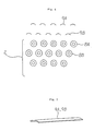
- Fig. 6 is a schematic transverse cross-section view showing the proximity of a heat transfer tube group
- Fig. 7 is a perspective view of a steel ball collision preventing plate in the same preferred embodiment.
- reference numeral 2 designates a heat transfer tube group, which is composed of a plurality of finned heat transfer tubes 8A, 8B, arranged in a zig-zag manner at a plurality of levels.
- first-level protectors (steel ball collision preventing plates) 9A and second-level protectors 9B are disposed respectively above first-level finned heat transfer tubes 8A and second-level finned heat transfer tubes 8B.
- Each of these protectors 9A and 9B is a steel plate having an upwardly convex curvature as shown in Fig.
- protectors 9A and 9B are disposed a steel ball scatterer similar to that in the prior art as described above with reference to Figs. 1 and 2, for example, a steel ball scatterer as illustrated in Fig. 3.
- steel balls fed through steel ball feeder pipes in a steel ball scatterer would fall and collide against a scattering plate and would fly and disperse in the circumferential direction, and they would fall towards the heat transfer tube group 2 under the scattering plate. And after they have once collided with the protectors 9A or 9B, they would be scattered again. In this way, while repeating collision and rescattering, the steel balls would fall through the heat transfer tube group 2 and thus remove soot and dust adhered to the finned heat transfer tubes 8A, 8B,---.
- an impact force of a steel ball scattered and dispersed by the steel ball scatterer is weakened by making it once collide with a protector, and so, even if it subsequently collides with a heat transfer tube, damage of a fin can be suppressed to minimum because its impact force has been weakened.
- a scattered density can be maintained uniform by employing the collision preventing plates 9A and 9B warped upwards.
- the material for the collision preventing plate not only metallic materials such as a steel plate or the like but also synthetic high-molecular material such as FRP or the like could be used depending upon a used temperature condition.
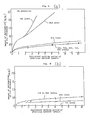
- test conditions are as follows:
- results of comparative tests for a damaged condition of a fin of a heat transfer tube are shown in Fig. 8.
- amounts of deformation of the fins on the heat transfer tubes at the first and second levels are such that after operation equivalent to working of a practical machine for about 2 years, deformation on one side of 1 mm is resulted, and similarly for about 4 years, deformation on one side of 1.7 - 2.3 mm is resulted.
- the present invention can bring about the following effects and advantages. That is, according to the present invention, in the case of removing soot and dust adhered to surfaces of heat transfer tubes in a heat-exchanger by scattering steel balls towards the heat transfer tubes, damage of the fins of the heat transfer tubes can be suppressed to minimum without largely degrading scattering characteristics of the steel balls, and so, a life of the heat transfer tubes can be greatly prolonged.
Landscapes
- Engineering & Computer Science (AREA)
- Chemical & Material Sciences (AREA)
- Combustion & Propulsion (AREA)
- Mechanical Engineering (AREA)
- General Engineering & Computer Science (AREA)
- Incineration Of Waste (AREA)
Applications Claiming Priority (5)
| Application Number | Priority Date | Filing Date | Title |
|---|---|---|---|
| JP52147/90U | 1990-05-21 | ||
| JP129292/90 | 1990-05-21 | ||
| JP5214790U JPH0417296U (fr) | 1990-05-21 | 1990-05-21 | |
| JP12929290A JP2691047B2 (ja) | 1990-05-21 | 1990-05-21 | 鋼球散布除煤方法 |
| EP91108180A EP0458263B1 (fr) | 1990-05-21 | 1991-05-21 | Méthode d'élimination de la suie par la distribution de billes d'acier dans un échangeur de chaleur |
Related Parent Applications (1)
| Application Number | Title | Priority Date | Filing Date |
|---|---|---|---|
| EP91108180.0 Division | 1991-05-21 |
Publications (2)
| Publication Number | Publication Date |
|---|---|
| EP0596538A1 true EP0596538A1 (fr) | 1994-05-11 |
| EP0596538B1 EP0596538B1 (fr) | 1997-09-10 |
Family
ID=26392763
Family Applications (2)
| Application Number | Title | Priority Date | Filing Date |
|---|---|---|---|
| EP93118919A Expired - Lifetime EP0596538B1 (fr) | 1990-05-21 | 1991-05-21 | Echangeur de chaleur comportant un dispositif pour distribuer des billes d'acier |
| EP91108180A Expired - Lifetime EP0458263B1 (fr) | 1990-05-21 | 1991-05-21 | Méthode d'élimination de la suie par la distribution de billes d'acier dans un échangeur de chaleur |
Family Applications After (1)
| Application Number | Title | Priority Date | Filing Date |
|---|---|---|---|
| EP91108180A Expired - Lifetime EP0458263B1 (fr) | 1990-05-21 | 1991-05-21 | Méthode d'élimination de la suie par la distribution de billes d'acier dans un échangeur de chaleur |
Country Status (4)
| Country | Link |
|---|---|
| US (1) | US5148857A (fr) |
| EP (2) | EP0596538B1 (fr) |
| DE (2) | DE69105819T2 (fr) |
| DK (2) | DK0596538T3 (fr) |
Families Citing this family (3)
| Publication number | Priority date | Publication date | Assignee | Title |
|---|---|---|---|---|
| CN101813430B (zh) * | 2009-02-20 | 2012-05-30 | 武汉东海石化重型装备有限公司 | 钢球换热系统 |
| US10371470B2 (en) | 2015-11-12 | 2019-08-06 | DOOSAN Heavy Industries Construction Co., LTD | Condenser tube cleaning apparatus |
| CN117249445A (zh) * | 2023-09-14 | 2023-12-19 | 中化节能技术(北京)有限公司 | 烟气换热清灰装置及烟气处理系统 |
Citations (2)
| Publication number | Priority date | Publication date | Assignee | Title |
|---|---|---|---|---|
| DE1263969B (de) * | 1965-03-19 | 1968-03-21 | Hoesch Ag | Prallverteiler fuer eine Kugelregenanlage |
| FR2022919A1 (fr) * | 1968-11-08 | 1970-08-07 | Husqvarna Licensing Ab |
Family Cites Families (9)
| Publication number | Priority date | Publication date | Assignee | Title |
|---|---|---|---|---|
| US2665118A (en) * | 1949-01-19 | 1954-01-05 | Ekstroems Maskinaffaer Ab | Apparatus for cleaning gas swept heating surfaces |
| US2665119A (en) * | 1949-03-08 | 1954-01-05 | Bror O Broman | Method and apparatus for cleaning gas-swept heating surfaces |
| US2809018A (en) * | 1951-11-15 | 1957-10-08 | Ekstroems Maskinaffaer Ab | Apparatus for distributing cleaning particles over gas-swept surfaces in heat exchangers and the like |
| US2949282A (en) * | 1954-11-23 | 1960-08-16 | Babcock & Wilcox Co | Apparatus for cleaning heat exchange means |
| US2962264A (en) * | 1956-04-21 | 1960-11-29 | K E Patenter Ab | Means for cleaning heating surfaces in economizers and similar equipment |
| DE2818006C2 (de) * | 1978-04-25 | 1980-04-24 | Ludwig Taprogge, Reinigungsanlagen Fuer Roehren-Waermeaustauscher, 4000 Duesseldorf | Röhrenwärmetauscher mit einer Reinigungseinrichtung |
| US4203778A (en) * | 1978-05-17 | 1980-05-20 | Union Carbide Corporation | Method for decoking fired heater tubes |
| NL186273C (nl) * | 1983-06-30 | 1990-10-16 | Ishikawajima Harima Heavy Ind | Inrichting voor het reinigen van de in hoofdzaak in horizontale richting lopende, buizen van een warmtewisselaar. |
| US4886112A (en) * | 1988-01-21 | 1989-12-12 | Ashland Oil, Inc. | Method for cleaning exterior surfaces of fire-heated tubes |
-
1991
- 1991-05-21 EP EP93118919A patent/EP0596538B1/fr not_active Expired - Lifetime
- 1991-05-21 EP EP91108180A patent/EP0458263B1/fr not_active Expired - Lifetime
- 1991-05-21 DK DK93118919.5T patent/DK0596538T3/da active
- 1991-05-21 DK DK91108180.0T patent/DK0458263T3/da active
- 1991-05-21 DE DE69105819T patent/DE69105819T2/de not_active Expired - Fee Related
- 1991-05-21 DE DE69127639T patent/DE69127639T2/de not_active Expired - Lifetime
- 1991-05-21 US US07/703,774 patent/US5148857A/en not_active Expired - Fee Related
Patent Citations (2)
| Publication number | Priority date | Publication date | Assignee | Title |
|---|---|---|---|---|
| DE1263969B (de) * | 1965-03-19 | 1968-03-21 | Hoesch Ag | Prallverteiler fuer eine Kugelregenanlage |
| FR2022919A1 (fr) * | 1968-11-08 | 1970-08-07 | Husqvarna Licensing Ab |
Also Published As
| Publication number | Publication date |
|---|---|
| EP0458263A1 (fr) | 1991-11-27 |
| EP0596538B1 (fr) | 1997-09-10 |
| DE69127639D1 (de) | 1997-10-16 |
| DK0596538T3 (da) | 1998-04-27 |
| DE69105819D1 (de) | 1995-01-26 |
| DE69127639T2 (de) | 1998-03-12 |
| US5148857A (en) | 1992-09-22 |
| EP0458263B1 (fr) | 1994-12-14 |
| DE69105819T2 (de) | 1995-06-08 |
| DK0458263T3 (da) | 1995-05-29 |
Similar Documents
| Publication | Publication Date | Title |
|---|---|---|
| Mitha et al. | The grain-bed impact process in aeolian saltation | |
| US3912471A (en) | High velocity moisture eliminator | |
| US7691349B2 (en) | Exhaust gas treating method | |
| US5584901A (en) | Dispersed phase separator | |
| US20050150439A1 (en) | Baffle for increased capture of popcorn ash in economizer hoppers | |
| CN111672859B (zh) | 用于高温气冷堆的收屑装置 | |
| EP0596538B1 (fr) | Echangeur de chaleur comportant un dispositif pour distribuer des billes d'acier | |
| US4580624A (en) | Louver fin evaporator | |
| US5172757A (en) | Method for removing soot by scattering steel balls in a heat-exchanger and heat-exchanger provided with a steel ball scatterer | |
| US4268287A (en) | Apparatus for improving particle separator efficiency | |
| EP0338928B1 (fr) | Echangeur de chaleur à caloducs | |
| US3275072A (en) | Radiator core guard | |
| US2876862A (en) | Dust separator | |
| US5372277A (en) | Ball dispensing unit | |
| US3534805A (en) | Method of cleaning the gas-swept heating surfaces in heat exchangers | |
| GB2142407A (en) | Cleaning heat exchangers | |
| EP3064833A1 (fr) | Appareil de collecte de cendres à grosses particules dans une installation d'énergie thermique | |
| US5507172A (en) | Apparatus to measure particle distribution of a shot stream | |
| JPH0233039Y2 (fr) | ||
| Pan et al. | Effects of target curvature on the impact characteristics of simulated hailstones | |
| JPH05223237A (ja) | 鋼球散布式除煤装置 | |
| JP3160433B2 (ja) | 鋼球散布除塵方法 | |
| JPS5918082B2 (ja) | 気液接触用充填材 | |
| JPH01249180A (ja) | 球状粒子の選別方法および選別装置 | |
| JP3310750B2 (ja) | 鋼球散布量制御方法 |
Legal Events
| Date | Code | Title | Description |
|---|---|---|---|
| PUAI | Public reference made under article 153(3) epc to a published international application that has entered the european phase |
Free format text: ORIGINAL CODE: 0009012 |
|
| 17P | Request for examination filed |
Effective date: 19931221 |
|
| AC | Divisional application: reference to earlier application |
Ref document number: 458263 Country of ref document: EP |
|
| AK | Designated contracting states |
Kind code of ref document: A1 Designated state(s): DE DK FR GB |
|
| 17Q | First examination report despatched |
Effective date: 19960710 |
|
| GRAG | Despatch of communication of intention to grant |
Free format text: ORIGINAL CODE: EPIDOS AGRA |
|
| GRAH | Despatch of communication of intention to grant a patent |
Free format text: ORIGINAL CODE: EPIDOS IGRA |
|
| GRAH | Despatch of communication of intention to grant a patent |
Free format text: ORIGINAL CODE: EPIDOS IGRA |
|
| GRAA | (expected) grant |
Free format text: ORIGINAL CODE: 0009210 |
|
| AC | Divisional application: reference to earlier application |
Ref document number: 458263 Country of ref document: EP |
|
| AK | Designated contracting states |
Kind code of ref document: B1 Designated state(s): DE DK FR GB |
|
| REF | Corresponds to: |
Ref document number: 69127639 Country of ref document: DE Date of ref document: 19971016 |
|
| ET | Fr: translation filed | ||
| REG | Reference to a national code |
Ref country code: DK Ref legal event code: T3 |
|
| PLBE | No opposition filed within time limit |
Free format text: ORIGINAL CODE: 0009261 |
|
| STAA | Information on the status of an ep patent application or granted ep patent |
Free format text: STATUS: NO OPPOSITION FILED WITHIN TIME LIMIT |
|
| 26N | No opposition filed | ||
| GBPC | Gb: european patent ceased through non-payment of renewal fee |
Effective date: 20000521 |
|
| REG | Reference to a national code |
Ref country code: DK Ref legal event code: EBP |
|
| REG | Reference to a national code |
Ref country code: FR Ref legal event code: ST |
|
| REG | Reference to a national code |
Ref country code: FR Ref legal event code: RN |
|
| REG | Reference to a national code |
Ref country code: GB Ref legal event code: 728V |
|
| REG | Reference to a national code |
Ref country code: FR Ref legal event code: FC |
|
| REG | Reference to a national code |
Ref country code: GB Ref legal event code: IF02 |
|
| REG | Reference to a national code |
Ref country code: GB Ref legal event code: 728Y |
|
| REG | Reference to a national code |
Ref country code: DK Ref legal event code: EGE |
|
| PGFP | Annual fee paid to national office [announced via postgrant information from national office to epo] |
Ref country code: GB Payment date: 20020502 Year of fee payment: 12 |
|
| PG25 | Lapsed in a contracting state [announced via postgrant information from national office to epo] |
Ref country code: GB Free format text: LAPSE BECAUSE OF NON-PAYMENT OF DUE FEES Effective date: 20030521 |
|
| GBPC | Gb: european patent ceased through non-payment of renewal fee |
Effective date: 20030521 |
|
| PGFP | Annual fee paid to national office [announced via postgrant information from national office to epo] |
Ref country code: FR Payment date: 20100525 Year of fee payment: 20 Ref country code: DK Payment date: 20100512 Year of fee payment: 20 |
|
| PGFP | Annual fee paid to national office [announced via postgrant information from national office to epo] |
Ref country code: DE Payment date: 20100519 Year of fee payment: 20 |
|
| REG | Reference to a national code |
Ref country code: DE Ref legal event code: R071 Ref document number: 69127639 Country of ref document: DE |
|
| REG | Reference to a national code |
Ref country code: DK Ref legal event code: EUP |
|
| PG25 | Lapsed in a contracting state [announced via postgrant information from national office to epo] |
Ref country code: DE Free format text: LAPSE BECAUSE OF EXPIRATION OF PROTECTION Effective date: 20110522 |