EP0596576A1 - Belüfteter Tank - Google Patents
Belüfteter Tank Download PDFInfo
- Publication number
- EP0596576A1 EP0596576A1 EP93203071A EP93203071A EP0596576A1 EP 0596576 A1 EP0596576 A1 EP 0596576A1 EP 93203071 A EP93203071 A EP 93203071A EP 93203071 A EP93203071 A EP 93203071A EP 0596576 A1 EP0596576 A1 EP 0596576A1
- Authority
- EP
- European Patent Office
- Prior art keywords
- tank
- duct
- vessel
- vessel according
- internal space
- Prior art date
- Legal status (The legal status is an assumption and is not a legal conclusion. Google has not performed a legal analysis and makes no representation as to the accuracy of the status listed.)
- Granted
Links
Images


Classifications
-
- B—PERFORMING OPERATIONS; TRANSPORTING
- B65—CONVEYING; PACKING; STORING; HANDLING THIN OR FILAMENTARY MATERIAL
- B65D—CONTAINERS FOR STORAGE OR TRANSPORT OF ARTICLES OR MATERIALS, e.g. BAGS, BARRELS, BOTTLES, BOXES, CANS, CARTONS, CRATES, DRUMS, JARS, TANKS, HOPPERS, FORWARDING CONTAINERS; ACCESSORIES, CLOSURES, OR FITTINGS THEREFOR; PACKAGING ELEMENTS; PACKAGES
- B65D90/00—Component parts, details or accessories for large containers
- B65D90/22—Safety features
- B65D90/32—Arrangements for preventing, or minimising the effect of, excessive or insufficient pressure
- B65D90/34—Venting means
Definitions
- the present invention relates to an unpressurised vessel for containing liquids which comprises a safety vent which allows venting to the atmosphere in such a way that, should the attitude of the vessel change, for instance following an accident involving a vehicle carrying the vessel, then the contents will be retained within the vessel with the minimum of loss.
- the invention is of particular use for transporting hot and/or dangerous liquids such as road dressing materials.
- US Patent No. 4,492,244 discloses a non-spill liquid fuel tank with a filler and a non-return vent arranged to vent the tank when in a generally upright attitude, comprising a fuel outlet duct extending to circuit the base of the tank, a first outlet duct vent having access to the outlet duct and extending to terminate at a position symmetrically disposed across the base of the tank to the access above the highest portion of the tank when in an upright attitude and a second outlet duct vent having access to the outlet duct beneath the position at which the first vent terminates and extending to terminate over the position at which the first vent has access to the outlet duct above the highest portion of the tank when in an upright attitude (Column 1, lines 41 to 54).
- the fuel tank is vented by means of a non-return vent consisting of a valve which allows air to enter the fuel tank to compensate for outflow of fuel through the fuel outlet duct, without allowing fuel to pass in the opposite direction (Column 3, lines 15 to 19).
- the fuel outlet duct and associated vents are arranged so that fuel is displaced from the fuel outlet duct by air drawn into the fuel outlet duct from the outlet duct vents when the tank is tilted from a generally upright attitude, thus preventing the unwanted escape of fuel from the fuel outlet duct (see Column 6, lines 8 to 13).
- non-spill tank described in US Patent No. 4,492,244 would be entirely unsuitable for transporting hot and/or dangerous liquids such as road dressing materials, as pressure build-up in the tank, being unable to vent to the atmosphere through the non-return vent, would act on the liquid contained in the tank causing it to be expelled from the outlet duct vents and to spill onto the roadway.
- the present invention seeks to provide a simple safety vent which overcomes the above problems.
- an unpressurised vessel for containing liquids comprising a tank having tank walls defining an internal space and having a safety vent which comprises a continuous duct having first and second ends, in which an orifice defines an outlet from the internal space, positioned towards the top of the internal space when the vessel is in its normal use orientation, and leads into the first end of the duct, and in which the duct extends around the tank tracing substantially the whole of the tank perimeter leading to the second duct end which is open to the atmosphere.
- the second duct end may be in a horizontal plane lower than the first duct end at the outlet from the internal space, it is preferable that the second duct end should in approximately the same horizontal plane as the first duct end, that is whilst the vessel is in its normal use orientation.
- the tank has first and second tank ends and the second duct end is located adjacent to the second tank end.
- the outlet from the internal space may conveniently be located adjacent to the first tank end or at a position between the first and second tank ends.
- the duct adjacent the first duct end the duct forms an inverted U-shape.
- an anti-siphoning device is provided inside the duct at the elbow of the U-shape section. Anti-siphoning devices are known and work by preventing any part of the channel inside the duct completely filling with liquid to the exclusion of all air, thereby preventing a condition under which siphoning could occur.
- the lowermost part of the duct or of each of two or more portions of the duct is furnished with a drainage valve. Should any liquid be ejected from internal space of the tank into the channel formed by the duct during normal operation, it can easily be removed via the drainage valves.
- the duct is in heat conduction contact with the internal space, which is usually heated.
- the heat conduction contact allows transfer of heat from the internal space of the tank through the duct walls so that any liquid in the channel is kept hot. This may be by forming the duct so that it forms part of the internal surface confining the internal space. Effectively therefore the duct is provided (i.e. located or positioned) inside the walls of the tank, i.e. the duct is provided internally of the tank walls.
- the heat conduction contact may be through the duct and the tank walls, that is where the duct is formed outside the tank walls, i.e. the duct is provided (i.e. located or positioned) externally of the tank walls.
- the walls of the tank and of the duct are made of metal e.g. steel.
- the duct is preferred for minimising the likelihood of spillage it is preferred for the duct to be provided on the outside (externally) of the tank walls.
- the invention is of particular use where the liquid contained in the tank is hot and/or dangerous.
- the liquids may therefore be a hydrocarbon fuel product or especially a road dressing material, for instance an emulsion or a liquid thermoplastic material.
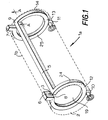
- FIG. 1 shows a vessel 1a comprising a circular cylindrical tank 1 b (denoted by a broken line) having tank walls defining an internal space 19 and having a safety vent which comprises a continuous duct 5 having a first duct end 6 and a second duct end 7.
- the vessel 1a is shown in its normal use orientation, wherein the longitudinal axis of the tank 1 is in a substantially horizontal orientation.
- the tank 1 has a first tank end 2 and a second tank end 14.
- the duct 5 then passes in an anti-clockwise direction substantially all around the inner circumference of the tank 1 b adjacent the first tank end 2 to the top point 8 adjacent the first tank end 2, from where it passes substantially horizontally inside the tank 1 to the top point 9 adjacent the second tank end 14, where it passes in a clockwise direction substantially all around the inner circumference of the tank 1 b adjacent the second tank end 14 to the second duct end 7.
- the second duct end 7 is open to the atmosphere.
- the duct 5 thus extends around the tank 1 tracing substantially the whole of the tank perimeter.
- the pathway for gas or vapour escape defined by a section 24 of the duct adjacent the first tank end extends in a different direction about the tank from that defined by a further section (25) of the duct adjacent the second tank end. In this way, a helical pathway for gas or vapour escape is avoided and thus there is less likelihood of spillage of liquid tank content if there is a change of orientation of the vessel, for example roll-over of the tank following an accident involving capsize of a vehicle carrying the vessel.
- drainage valves 10, 11 are located at the lowermost parts of the duct 5 adjacent the first 2 and second 14 tank ends.
- FIG 2 shows a section through the tank 1 b and the duct 5 of Figure 1 adjacent the second tank end 14.
- the duct 5 is formed of a substantially U-section strip of material 15, which is attached to the wall 4 of the tank 1 b via the arms of the U 16, 17.
- the tank wall 4 and the U-section strip of material 15 are for instance formed of steel or other suitable metal.
- the duct 5 forms a channel 18.
- the duct 5 is in heat conducting contact with the internal space 19 within the tank 1 b, heat being able to be conducted through the wall 15 of the duct 5.
- FIG. 3 an alternative mode of construction of duct is illustrated.
- a substantially square section duct 20 is attached externally of the wall 4 of the tank, via a U-section retaining strip 21 provided with flanges 22 which can be attached to the tank wall 4 by welding, rivetting or other suitable means.
- the duct 20 forms a channel 18a.
- the duct 20 is in direct contact with the wall 4 of the tank along contacting surface 23. Heat conduction can take place between the duct 20 and the internal space 19a via the contacting surface 23.
- Figure 4 shows a vessel 1 similar to that of Figure 1, except that the orifice 3 defining an outlet from the internal space 19 of the tank 1 b is located towards the top of the internal space 19 at a position between and substantially equidistant from the first tank end 2 and the second tank end 14.
- the tank In the venting mode, under normal transport conditions, the tank is vented via the orifice 3 into U-section of the duct. Due to pressure any gas or vapour is forced around the channel within the duct around the end 2 of the tank, and along the continuous channel to the second end 7 of the duct, where it is vented to the atmosphere through the open end or via a flame-arresting device.
Landscapes
- Engineering & Computer Science (AREA)
- Mechanical Engineering (AREA)
- Cooling, Air Intake And Gas Exhaust, And Fuel Tank Arrangements In Propulsion Units (AREA)
Applications Claiming Priority (2)
| Application Number | Priority Date | Filing Date | Title |
|---|---|---|---|
| EP92310082 | 1992-11-04 | ||
| EP92310082 | 1992-11-04 |
Publications (2)
| Publication Number | Publication Date |
|---|---|
| EP0596576A1 true EP0596576A1 (de) | 1994-05-11 |
| EP0596576B1 EP0596576B1 (de) | 1997-03-26 |
Family
ID=8211544
Family Applications (1)
| Application Number | Title | Priority Date | Filing Date |
|---|---|---|---|
| EP19930203071 Expired - Lifetime EP0596576B1 (de) | 1992-11-04 | 1993-11-02 | Belüfteter Tank |
Country Status (2)
| Country | Link |
|---|---|
| EP (1) | EP0596576B1 (de) |
| DE (1) | DE69309218D1 (de) |
Citations (3)
| Publication number | Priority date | Publication date | Assignee | Title |
|---|---|---|---|---|
| US3966078A (en) * | 1973-10-09 | 1976-06-29 | Brown-Minneapolis Tank & Fabricating Co. | Tank vent |
| JPS57167826A (en) * | 1981-11-27 | 1982-10-15 | Toyota Motor Corp | Fuel vapor pipe of automobile fuel tank |
| US4492244A (en) * | 1982-03-29 | 1985-01-08 | Secretary of State for Her Majesty's Government of the United Kingdom and Britain | Non-spill liquid fuel tanks |
-
1993
- 1993-11-02 EP EP19930203071 patent/EP0596576B1/de not_active Expired - Lifetime
- 1993-11-02 DE DE69309218T patent/DE69309218D1/de not_active Expired - Lifetime
Patent Citations (3)
| Publication number | Priority date | Publication date | Assignee | Title |
|---|---|---|---|---|
| US3966078A (en) * | 1973-10-09 | 1976-06-29 | Brown-Minneapolis Tank & Fabricating Co. | Tank vent |
| JPS57167826A (en) * | 1981-11-27 | 1982-10-15 | Toyota Motor Corp | Fuel vapor pipe of automobile fuel tank |
| US4492244A (en) * | 1982-03-29 | 1985-01-08 | Secretary of State for Her Majesty's Government of the United Kingdom and Britain | Non-spill liquid fuel tanks |
Non-Patent Citations (1)
| Title |
|---|
| PATENT ABSTRACTS OF JAPAN vol. 7, no. 9 (M - 185)<1154> 14 January 1983 (1983-01-14) * |
Also Published As
| Publication number | Publication date |
|---|---|
| EP0596576B1 (de) | 1997-03-26 |
| DE69309218D1 (de) | 1997-04-30 |
Similar Documents
| Publication | Publication Date | Title |
|---|---|---|
| EP0569222B1 (de) | Aussgiesser | |
| EP0534752B1 (de) | Ausgiesser | |
| EP0437053A1 (de) | Austrittsverhindernde Brennstoff-Füllvorrichtung | |
| US4347878A (en) | Funnel | |
| US5381923A (en) | Overflow control for liquid storage tanks | |
| US5597097A (en) | Fluid dispensing container | |
| US3917109A (en) | Evaporative emission controls | |
| US6213170B1 (en) | Valveless fuel tank assembly | |
| US3542239A (en) | Fuel tank vapor separator system | |
| US5507328A (en) | Pouring spout | |
| US4120414A (en) | Self-venting cap | |
| US4457443A (en) | Motor vehicle fuel tank venting device | |
| JPS5828129B2 (ja) | トクニジドウシヤヨウヨウ ノ ネンリヨウヨウキ ノ カンキソウチ | |
| US5894809A (en) | Fuel overflow prevention device and method | |
| US4842152A (en) | Spill proof plug | |
| EP0596576A1 (de) | Belüfteter Tank | |
| CA1280980C (en) | Fuel tank for an off-road vehicle | |
| JPH0747372B2 (ja) | 自動車の燃料タンク用ガス抜き装置 | |
| US3698160A (en) | Motor vehicle fuel tank venting | |
| US5404903A (en) | Smart vent valve for cargo tanks employed in transporting hazardous commodities | |
| GB2248228A (en) | A fuel tank assembly | |
| US4318348A (en) | Railroad tank car | |
| EP0090537B1 (de) | Auslaufsicherer Kraftstoffbehälter | |
| US3927702A (en) | Emergency over-fill assembly for marine vessels | |
| EP0042214B1 (de) | Flüssigkeitsbehälter, eingerichtet zur Begrenzung unerwünschter Entleerung |
Legal Events
| Date | Code | Title | Description |
|---|---|---|---|
| PUAI | Public reference made under article 153(3) epc to a published international application that has entered the european phase |
Free format text: ORIGINAL CODE: 0009012 |
|
| AK | Designated contracting states |
Kind code of ref document: A1 Designated state(s): DE ES FR GB IT |
|
| 17P | Request for examination filed |
Effective date: 19940906 |
|
| 17Q | First examination report despatched |
Effective date: 19950920 |
|
| RAP1 | Party data changed (applicant data changed or rights of an application transferred) |
Owner name: COLAS S.A. |
|
| GRAG | Despatch of communication of intention to grant |
Free format text: ORIGINAL CODE: EPIDOS AGRA |
|
| GRAH | Despatch of communication of intention to grant a patent |
Free format text: ORIGINAL CODE: EPIDOS IGRA |
|
| GRAH | Despatch of communication of intention to grant a patent |
Free format text: ORIGINAL CODE: EPIDOS IGRA |
|
| GRAA | (expected) grant |
Free format text: ORIGINAL CODE: 0009210 |
|
| AK | Designated contracting states |
Kind code of ref document: B1 Designated state(s): DE ES FR GB IT |
|
| PG25 | Lapsed in a contracting state [announced via postgrant information from national office to epo] |
Ref country code: IT Free format text: LAPSE BECAUSE OF FAILURE TO SUBMIT A TRANSLATION OF THE DESCRIPTION OR TO PAY THE FEE WITHIN THE PRESCRIBED TIME-LIMIT;WARNING: LAPSES OF ITALIAN PATENTS WITH EFFECTIVE DATE BEFORE 2007 MAY HAVE OCCURRED AT ANY TIME BEFORE 2007. THE CORRECT EFFECTIVE DATE MAY BE DIFFERENT FROM THE ONE RECORDED. Effective date: 19970326 Ref country code: FR Effective date: 19970326 Ref country code: ES Free format text: THE PATENT HAS BEEN ANNULLED BY A DECISION OF A NATIONAL AUTHORITY Effective date: 19970326 |
|
| REF | Corresponds to: |
Ref document number: 69309218 Country of ref document: DE Date of ref document: 19970430 |
|
| PG25 | Lapsed in a contracting state [announced via postgrant information from national office to epo] |
Ref country code: DE Effective date: 19970627 |
|
| EN | Fr: translation not filed | ||
| PLBE | No opposition filed within time limit |
Free format text: ORIGINAL CODE: 0009261 |
|
| 26N | No opposition filed | ||
| REG | Reference to a national code |
Ref country code: GB Ref legal event code: IF02 |
|
| PGFP | Annual fee paid to national office [announced via postgrant information from national office to epo] |
Ref country code: GB Payment date: 20021030 Year of fee payment: 10 |
|
| PG25 | Lapsed in a contracting state [announced via postgrant information from national office to epo] |
Ref country code: GB Free format text: LAPSE BECAUSE OF NON-PAYMENT OF DUE FEES Effective date: 20031102 |
|
| GBPC | Gb: european patent ceased through non-payment of renewal fee |
Effective date: 20031102 |