EP0596608A2 - Support de câble accessible par le côté - Google Patents
Support de câble accessible par le côté Download PDFInfo
- Publication number
- EP0596608A2 EP0596608A2 EP93308049A EP93308049A EP0596608A2 EP 0596608 A2 EP0596608 A2 EP 0596608A2 EP 93308049 A EP93308049 A EP 93308049A EP 93308049 A EP93308049 A EP 93308049A EP 0596608 A2 EP0596608 A2 EP 0596608A2
- Authority
- EP
- European Patent Office
- Prior art keywords
- support fitting
- assembly
- conduit
- set forth
- further characterized
- Prior art date
- Legal status (The legal status is an assumption and is not a legal conclusion. Google has not performed a legal analysis and makes no representation as to the accuracy of the status listed.)
- Withdrawn
Links
Images

Classifications
-
- F—MECHANICAL ENGINEERING; LIGHTING; HEATING; WEAPONS; BLASTING
- F16—ENGINEERING ELEMENTS AND UNITS; GENERAL MEASURES FOR PRODUCING AND MAINTAINING EFFECTIVE FUNCTIONING OF MACHINES OR INSTALLATIONS; THERMAL INSULATION IN GENERAL
- F16C—SHAFTS; FLEXIBLE SHAFTS; ELEMENTS OR CRANKSHAFT MECHANISMS; ROTARY BODIES OTHER THAN GEARING ELEMENTS; BEARINGS
- F16C1/00—Flexible shafts; Mechanical means for transmitting movement in a flexible sheathing
- F16C1/10—Means for transmitting linear movement in a flexible sheathing, e.g. "Bowden-mechanisms"
- F16C1/106—Plurality of transmitting means, e.g. two or more parallel "Bowden cables"
-
- F—MECHANICAL ENGINEERING; LIGHTING; HEATING; WEAPONS; BLASTING
- F16—ENGINEERING ELEMENTS AND UNITS; GENERAL MEASURES FOR PRODUCING AND MAINTAINING EFFECTIVE FUNCTIONING OF MACHINES OR INSTALLATIONS; THERMAL INSULATION IN GENERAL
- F16C—SHAFTS; FLEXIBLE SHAFTS; ELEMENTS OR CRANKSHAFT MECHANISMS; ROTARY BODIES OTHER THAN GEARING ELEMENTS; BEARINGS
- F16C1/00—Flexible shafts; Mechanical means for transmitting movement in a flexible sheathing
- F16C1/10—Means for transmitting linear movement in a flexible sheathing, e.g. "Bowden-mechanisms"
- F16C1/102—Arrangements to mount end fittings of the sheathings to support walls or brackets
- F16C1/105—Arrangements to mount end fittings of the sheathings to support walls or brackets to a slot in the bracket
-
- F—MECHANICAL ENGINEERING; LIGHTING; HEATING; WEAPONS; BLASTING
- F16—ENGINEERING ELEMENTS AND UNITS; GENERAL MEASURES FOR PRODUCING AND MAINTAINING EFFECTIVE FUNCTIONING OF MACHINES OR INSTALLATIONS; THERMAL INSULATION IN GENERAL
- F16C—SHAFTS; FLEXIBLE SHAFTS; ELEMENTS OR CRANKSHAFT MECHANISMS; ROTARY BODIES OTHER THAN GEARING ELEMENTS; BEARINGS
- F16C1/00—Flexible shafts; Mechanical means for transmitting movement in a flexible sheathing
- F16C1/26—Construction of guiding-sheathings or guiding-tubes
- F16C1/262—End fittings; Attachment thereof to the sheathing or tube
-
- F—MECHANICAL ENGINEERING; LIGHTING; HEATING; WEAPONS; BLASTING
- F16—ENGINEERING ELEMENTS AND UNITS; GENERAL MEASURES FOR PRODUCING AND MAINTAINING EFFECTIVE FUNCTIONING OF MACHINES OR INSTALLATIONS; THERMAL INSULATION IN GENERAL
- F16C—SHAFTS; FLEXIBLE SHAFTS; ELEMENTS OR CRANKSHAFT MECHANISMS; ROTARY BODIES OTHER THAN GEARING ELEMENTS; BEARINGS
- F16C2226/00—Joining parts; Fastening; Assembling or mounting parts
- F16C2226/50—Positive connections
- F16C2226/70—Positive connections with complementary interlocking parts
- F16C2226/74—Positive connections with complementary interlocking parts with snap-fit, e.g. by clips
-
- F—MECHANICAL ENGINEERING; LIGHTING; HEATING; WEAPONS; BLASTING
- F16—ENGINEERING ELEMENTS AND UNITS; GENERAL MEASURES FOR PRODUCING AND MAINTAINING EFFECTIVE FUNCTIONING OF MACHINES OR INSTALLATIONS; THERMAL INSULATION IN GENERAL
- F16C—SHAFTS; FLEXIBLE SHAFTS; ELEMENTS OR CRANKSHAFT MECHANISMS; ROTARY BODIES OTHER THAN GEARING ELEMENTS; BEARINGS
- F16C2300/00—Application independent of particular apparatuses
- F16C2300/02—General use or purpose, i.e. no use, purpose, special adaptation or modification indicated or a wide variety of uses mentioned
-
- Y—GENERAL TAGGING OF NEW TECHNOLOGICAL DEVELOPMENTS; GENERAL TAGGING OF CROSS-SECTIONAL TECHNOLOGIES SPANNING OVER SEVERAL SECTIONS OF THE IPC; TECHNICAL SUBJECTS COVERED BY FORMER USPC CROSS-REFERENCE ART COLLECTIONS [XRACs] AND DIGESTS
- Y10—TECHNICAL SUBJECTS COVERED BY FORMER USPC
- Y10T—TECHNICAL SUBJECTS COVERED BY FORMER US CLASSIFICATION
- Y10T24/00—Buckles, buttons, clasps, etc.
- Y10T24/34—Combined diverse multipart fasteners
- Y10T24/3427—Clasp
- Y10T24/3439—Plural clasps
- Y10T24/344—Resilient type clasp
- Y10T24/3444—Circular work engageable
-
- Y—GENERAL TAGGING OF NEW TECHNOLOGICAL DEVELOPMENTS; GENERAL TAGGING OF CROSS-SECTIONAL TECHNOLOGIES SPANNING OVER SEVERAL SECTIONS OF THE IPC; TECHNICAL SUBJECTS COVERED BY FORMER USPC CROSS-REFERENCE ART COLLECTIONS [XRACs] AND DIGESTS
- Y10—TECHNICAL SUBJECTS COVERED BY FORMER USPC
- Y10T—TECHNICAL SUBJECTS COVERED BY FORMER US CLASSIFICATION
- Y10T24/00—Buckles, buttons, clasps, etc.
- Y10T24/39—Cord and rope holders
- Y10T24/3969—Sliding part or wedge
- Y10T24/3973—Rope clamped between cone and socket
-
- Y—GENERAL TAGGING OF NEW TECHNOLOGICAL DEVELOPMENTS; GENERAL TAGGING OF CROSS-SECTIONAL TECHNOLOGIES SPANNING OVER SEVERAL SECTIONS OF THE IPC; TECHNICAL SUBJECTS COVERED BY FORMER USPC CROSS-REFERENCE ART COLLECTIONS [XRACs] AND DIGESTS
- Y10—TECHNICAL SUBJECTS COVERED BY FORMER USPC
- Y10T—TECHNICAL SUBJECTS COVERED BY FORMER US CLASSIFICATION
- Y10T74/00—Machine element or mechanism
- Y10T74/20—Control lever and linkage systems
- Y10T74/20396—Hand operated
- Y10T74/20402—Flexible transmitter [e.g., Bowden cable]
- Y10T74/2045—Flexible transmitter [e.g., Bowden cable] and sheath support, connector, or anchor
-
- Y—GENERAL TAGGING OF NEW TECHNOLOGICAL DEVELOPMENTS; GENERAL TAGGING OF CROSS-SECTIONAL TECHNOLOGIES SPANNING OVER SEVERAL SECTIONS OF THE IPC; TECHNICAL SUBJECTS COVERED BY FORMER USPC CROSS-REFERENCE ART COLLECTIONS [XRACs] AND DIGESTS
- Y10—TECHNICAL SUBJECTS COVERED BY FORMER USPC
- Y10T—TECHNICAL SUBJECTS COVERED BY FORMER US CLASSIFICATION
- Y10T74/00—Machine element or mechanism
- Y10T74/20—Control lever and linkage systems
- Y10T74/20396—Hand operated
- Y10T74/20402—Flexible transmitter [e.g., Bowden cable]
- Y10T74/20462—Specific cable connector or guide
Definitions
- the subject invention relates to motion transmitting remote control cable assemblies of the type for transmitting motion in a curved path by means of a flexible motion transmitting core element, and more particularly to assemblies for supporting motion transmitting cables as they pass through a support structure.
- Motion transmitting remote control cables require support brackets for support as they pass through a support structure such as a bulkhead. It is well known in the art to mold a bracket or support fitting around one or more conduits of a cable system. However, this molding process is time consuming, expensive, and not flexible enough to easily meet the needs of customers. Support fittings of the type described in U.S. Patent number 4,951,524, of common assignee herewith, allow the support fitting to be molded separate from the conduit, and thus many of the problems described above can be avoided. In this case, the conduit can snap into an opening in the fitting at whatever stage in the manufacturing process this is desired.
- a motion transmitting remote control cable assembly for transmitting motion in a curved path comprises a first core element and a first motion transmitting core element slideably supported in the first conduit.
- the assembly also includes a support fitting for supporting the first conduit as the first conduit passes through a slot in a support structure.
- the support fitting includes first and second sides with guides along the sides for sliding into engagement with the slot in the support structure and retaining the support fitting in the slot.
- the assembly is characterized by the support fitting including receiving means extending transversely to the first side for receiving at least one conduit transversely of the sides.
- this type of support fitting can support several conduits as they pass through the support structure.
- the assembly 10 also includes a support fitting generally indicated at 20 for supporting the first conduit 14 as the first conduit passes through a slot 22 in a support structure 24.
- the support fitting 20 includes first and second sides 26,28 with guides 30 along the sides for sliding into engagement with the slot 22 in the support structure 24 and retaining the support fitting in the slot.
- the assembly 10 is characterized by the support fitting 20 including receiving means 32 extending transversely to the first side 26 for receiving at least one conduit 14 transversely of the sides 26,28.
- the assembly 10 includes a second conduit 18 and a second motion transmitting core element 16 slideably suppported in the second conduit 18, where the second conduit 18 passes through the slot 22 in the support structure 24 generally parallel to the first conduit 14.
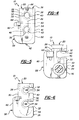
- the first embodiment is a "side slide yoke" version (shown in Figures 1,2,3,5 and 6) where one or more conduits 14,18 each slide into a "U” shaped opening 32 in the side of the support fitting 20;
- the second embodiment is a hinged version (shown in Figure 4) where one or more conduits 14,18 each slide into a "U” shaped opening 32 in the side of the support fitting 20, and then the side of the support fitting is closed with closing means generally indicated at 36 prior to inserting the support fitting into the slot 22 in the support fitting.
- the support fitting 20 is molded around one or more of the conduits 14,18, while there is one "U" shaped opening 32 in the first side 26 of the support fitting for receiving an additional conduit.
- the two conduits 14,18 pass through the support fitting 20 in an over-and-under coaxial type of arrangement.
- the receiving means 32 includes two "U" shaped openings in the first side 26 of the support fitting 20 each for slideably receiving a conduit 14,18. None of the conduits 14,18 are molded to the support fitting 20. Instead, both can slide into place in the support fitting 20. These openings 32 are also in over-and-under coaxial arrangement.
- the "U" shaped opening or openings 32 in the first side 26 of the supportfitting 20 have a constriction 34 constricting the "U" shaped opening or openings 32 for allowing one of the conduits 14,18 to snap into each of the openings and for retaining the conduit within the opening 32.
- the wall of each of the openings 32 defines a throat 34 in the opening 32.
- the throat or constriction 34 can widen or deform under a predetermined force to receive the conduit 14,18 and then snap back into place. In this way, the conduit 14,18 will be retained within the opening 32 by the constriction 34 or throat.
- the constriction 34 serves mainly to retain the conduit during shipping and pre-assembly.
- the conduit will be retained in the opening 34 by the wall of the support structure 24, and the constrictions 34 become superfluous.
- the hinged embodiment of the support fitting 20 (shown in Figure 4) includes closing means generally indicated at 36 for closing the "U" shaped openings 32 and retaining the conduits 14,18 within the support fitting.
- the closing means 36 includes a closing member 38 contacting the first side 26 of the support fitting 20 and closing the "U" shaped openings 32.
- the closing member 38 includes first and second semicircular pockets 40 corresponding with the first and second "U" shaped openings 32 on the support fitting 20 for retaining the conduits 14,18 between the supportfitting and the closing member 38 when the pockets 40 on the closing member are aligned with the "U" shaped openings 32 on the support fitting.
- the closing means 36 includes a hinge 42 interconnecting the support fitting 20 and the closing member 38.
- the closing means 36 also includes retaining means 44 for retaining the support fitting 20 and the closing member 38 together and preventing the movement of same about the hinge 42.
- the retaining means 44 includes a clip 44 disposed on an end of the support fitting 20 opposite the hinge 42 for clipping the supportfitting and the closing member38 together.
- the hinge 42 is disposed so that the closing member 38 and the support fitting 20 can rotate about an axis which is parallel to the axes through the openings 32.
- Each conduit 14,16 includes a flange 46 disposed therearound at a predetermined point along the length of the conduit.
- the support fitting 20 includes a groove 48 following the contour of each of the "U" shaped openings 32 for guiding and retaining the flange 46 on the conduit 14,18.
- the conduit 14,18 will include a ferrule end fitting 15 for sliding into engagement with the openings 32.
- This type of end fitting includes the flange 46 and a parallel flange 47 parallel to the flange 46. When the conduit slides into the opening 32, the flange 46 will fit in the groove 48, and the parallel flange 47 will engage the front or back of the support fitting.
- This two flange design provides a firm connection between the conduit 14,16 and the support fitting 20.
- All embodiments and versions of the support fitting 20 include a body 50 having a first side, a second side, a top, a bottom, a front and a back.
- the guides 30 include spaced apart front and back flanges 52,54 disposed adjacent the front and back, respectively, and extending away from the body 50 and down the first side, around the bottom side and up the second side.
- the spaced apart flanges 52,54 define a guide track 56 for receiving the support structure 24, guiding the support fitting 20 as same slides in bottom-first fashion into the slot 22 (as shown in Figure 1)and for bracing the support fitting against back and forth movement within the slot by retaining the support structure 24 between the flanges.
- the body 50 is the support fitting 20 itself. But in the "hinged” embodiment, the body 50 is actually the support fitting 20 and the closing member 38 together.
- the guide track 56 extends down the side of the closing member 38 opposite the side engaging the support fitting 20: the guide track 56 then extends along the bottom of the closing member 38, along the bottom of the support fitting 20, and up the side of the support fitting opposite the side engaging the closing member 38.
- the end fitting 15 on the conduits 14,18 has a "D" shape adapted to fill the "U" shaped opening 32 in the support fitting 20.
- the upright portion of the "D" shaped fitting 15 includes spaced apart flanges defining a track 57.
- the track 57 is flush with the portion of the guide track 56 which runs down the first side 26 of the end fitting 20. In this way a track 56,57 will extend in unbroken fashion down the first side 26 of the support fitting 20.
- All embodiments of the assembly 10 further include locking means generally indicated at 58 for locking the support fitting 20 to the support structure 24.
- the locking means 58 includes a locking arm 60 extending away from the second side of the support fitting 20, the locking arm being flexible to allow the arm to deflect with respect to the support fitting.
- the locking arm 60 usually extends from the rearflange 54 on the second side 28 of the support fitting 20, though it can also be adapted to extend from the front flange 52 as well.
- the locking means 58 also includes a locking finger 62 extending generally perpendicularly away from the locking arm 60 for positioning in a hole 64 in the support structure 24.
- the locking finger 62 is generally cylindrical in shape, but it includes a tapered lower surface 66 to prevent the finger from catching on the wall of the support structure 24 when the support fitting 20 is slid into the slot 22 through the support structure.
- the assembly 10 finally includes a back stop 68 extending from the second side of the support fitting 20 behind the locking arm 60.
- the back stop 68 is spaced apart from the back side of the locking arm 60 behind the locking finger 62 to prevent damage to the locking arm in two ways: the back stop prevents the locking arm from deflecting more than a predetermined distance when a force is applied to the locking arm at the front side; and the back stop 68 prevents objects from even touching the locking arm from the back side.
- the deflection of the locking arm 68 is controlled when the support fitting 20 is inserted in the support structure 24.
- the back stop 68 also protects the locking arm 60 during shipping by preventing excess bending of the locking arm while the support fitting 20 is in a box with many other support fittings.
- the support fitting 20 will be molded to include a molding hole 70 between the places where the two conduits 14,18, pass through.
- the support fitting 20 is molded with the molding hole 70 to facilitate the molding of the part by ensuring uniformity of wall thickness and strength.
- the existence of the molding hole 70 also saves on material. This molding practice is well known in the plastic molding art.
- each conduit 14,16 is inserted in its respective opening 32 in the first side of the support fitting 20. If there is only one opening 32, then only one conduit is inserted. If there are two openings 32, then two conduits 14,18 are inserted, one in each opening. This of course varies with the embodiment or version of the assembly being used. If the hinged embodiment is used, the conduits 14,18 are inserted into their respective openings 32, and the closing member 38 rotates about the hinge 42 into engagement with the support fitting 20 and the clip 44 snaps the closing member and the support fitting together. Then, the assembly 10 (regardless of embodiment or version) is inserted into the slot 22 in the support structure 24 so that the wall of the support fitting 24 slides in the track 56.
- the tapered surface 66 of the locking finger 62 hits the wall of the support structure 24.
- the downward movement of the assembly 10 into the slot 22 forces the finger, and thus the locking arm 60 to deflect back to prevent the finger 62 from catching on the wait.
- the elasticity orflexibility of the locking arm 60 biases the finger 62 against the wall as the assembly 10 slides further into place.
- the finger will find the hole 64 in the wall and the locking arm 60 will bias the finger 62 into the hole 64. Now, the assembly 10 is fully inserted in the slot 22 and the locking finger 62 retains the assembly in this position.
- the conduit or conduits 14,18 are fixed within the support fitting 20 in all versions and embodiments: in the case of the "side slide yoke," the wall of the support structure 24 closes each opening 32 in which a conduit 14,18 is inserted; in the case of the hinged version, the walls of the support structure 24 defining the slot 22 maintain the support fitting 20 and the closing member 38 together, and thus retain the conduit or conduits 14,18 within the support fitting.
Landscapes
- Engineering & Computer Science (AREA)
- General Engineering & Computer Science (AREA)
- Health & Medical Sciences (AREA)
- Oral & Maxillofacial Surgery (AREA)
- Mechanical Engineering (AREA)
- Supports For Pipes And Cables (AREA)
Applications Claiming Priority (2)
| Application Number | Priority Date | Filing Date | Title |
|---|---|---|---|
| US972846 | 1992-11-06 | ||
| US07/972,846 US5272934A (en) | 1992-11-06 | 1992-11-06 | Side access conduit support fitting |
Publications (2)
| Publication Number | Publication Date |
|---|---|
| EP0596608A2 true EP0596608A2 (fr) | 1994-05-11 |
| EP0596608A3 EP0596608A3 (en) | 1994-06-29 |
Family
ID=25520217
Family Applications (1)
| Application Number | Title | Priority Date | Filing Date |
|---|---|---|---|
| EP19930308049 Withdrawn EP0596608A3 (en) | 1992-11-06 | 1993-10-08 | Side access conduit support fitting |
Country Status (3)
| Country | Link |
|---|---|
| US (1) | US5272934A (fr) |
| EP (1) | EP0596608A3 (fr) |
| CA (1) | CA2108220A1 (fr) |
Cited By (1)
| Publication number | Priority date | Publication date | Assignee | Title |
|---|---|---|---|---|
| CN1311598C (zh) * | 2002-02-18 | 2007-04-18 | 株式会社大井制作所 | 控制电缆的安装装置 |
Families Citing this family (28)
| Publication number | Priority date | Publication date | Assignee | Title |
|---|---|---|---|---|
| JP2848730B2 (ja) * | 1992-01-21 | 1999-01-20 | 日産自動車株式会社 | コントロールケーブルの調整装置 |
| US5371969A (en) * | 1993-10-08 | 1994-12-13 | C. A. P., Inc. | Spray shield |
| US5553818A (en) * | 1994-08-29 | 1996-09-10 | Hi-Lex Corporation | Conduit end fitting with lock condition indicator |
| DE4438057C1 (de) * | 1994-10-25 | 1995-12-07 | Bauknecht Hausgeraete | Vorrichtung zum Festlegen eines Ablaufschlauches und eines Zulaufschlauches oder Zulaufventils bei einem Haushaltgerät, wie Waschmaschine, Geschirrspüler u. dgl. |
| US5596908A (en) * | 1995-08-28 | 1997-01-28 | Teleflex Incorporated | Lock for slide and lock L-arm |
| US5579662A (en) * | 1995-08-29 | 1996-12-03 | Teleflex Incorporated | Low force slide-n-snap high force retention |
| US5613406A (en) * | 1995-10-26 | 1997-03-25 | Teleflex Incorporated | Rotating slide-n-snap |
| US5615584A (en) * | 1995-11-21 | 1997-04-01 | Teleflex Incorporated | Slide n' snap with living hinge lock |
| USD417135S (en) | 1996-06-10 | 1999-11-30 | Zardoz Pty Limited | Conduit positioning device |
| FR2751722B1 (fr) * | 1996-07-24 | 1998-09-18 | Bundy | Dispositif de fixation destine a assujettir un organe de jonction de tubes a une plaquette qu'il traverse par une ouverture associee |
| ES2117956B1 (es) * | 1996-12-03 | 1999-04-01 | Fico Cables Sa | Terminal de funda para cables de mando. |
| US5836212A (en) * | 1997-05-21 | 1998-11-17 | Teleflex, Inc. | Interlocking grommet with gross hole and method of assembly |
| US5953963A (en) * | 1998-07-06 | 1999-09-21 | General Motors Corporation | Cable-to-lever connection for motion-transmitting mechanism |
| US6092436A (en) * | 1998-07-28 | 2000-07-25 | General Motors Corporation | Anchorage for motion-transmitting cable assembly |
| US6171014B1 (en) | 1998-11-03 | 2001-01-09 | Illinois Tool Works, Inc. | Clip with sliding lid for an automotive seat and similar applications |
| US6508440B2 (en) | 2000-12-08 | 2003-01-21 | Beverly Manufacturing Co. | One-piece conduit hanger |
| JP2003092820A (ja) * | 2001-09-19 | 2003-03-28 | Mitsumi Electric Co Ltd | ケーブル取付構造 |
| EP1498620B1 (fr) | 2003-07-18 | 2008-11-05 | Fico Triad | Elément de montage pour un cable Bowden |
| US20080196531A1 (en) * | 2004-02-23 | 2008-08-21 | Dura Global Technologies, Inc. | Terminal connectors and terminal connector assemblies |
| US20090211388A1 (en) * | 2008-02-21 | 2009-08-27 | Patrick Eugene Meysenburg | Pull-pull type shifter control cable |
| CN102317636B (zh) | 2008-12-15 | 2014-07-30 | 康斯博动力传动系统公司 | 具有固定夹的装配件 |
| DE102009002197A1 (de) * | 2009-04-06 | 2010-10-14 | Robert Bosch Gmbh | Befestigungseinrichtung für ein Kabel |
| KR101251981B1 (ko) * | 2011-12-05 | 2013-04-08 | 주식회사 대동시스템 | 자동차 케이블 지지클립 |
| IN2012DE00583A (fr) * | 2012-03-01 | 2015-08-21 | Inteva Products Llc | |
| KR101495512B1 (ko) * | 2013-05-06 | 2015-02-25 | 경창산업주식회사 | 역조립 방지 케이블 고정용 클립 |
| CN114086840A (zh) | 2014-12-27 | 2022-02-25 | 因特瓦产品有限责任公司 | 用于车辆锁闩中的窗板按钮界面的整体杆结构 |
| DE102015108193A1 (de) * | 2015-05-22 | 2016-11-24 | Huf Hülsbeck & Fürst Gmbh & Co. Kg | Aufnahmeelement für eine Türgriffvorrichtung |
| TWI621383B (zh) * | 2016-03-30 | 2018-04-11 | 群光電能科技股份有限公司 | 電子裝置及其組配方法 |
Family Cites Families (18)
| Publication number | Priority date | Publication date | Assignee | Title |
|---|---|---|---|---|
| US2542442A (en) * | 1945-07-23 | 1951-02-20 | Hughes Tool Co | Tube support |
| GB1075301A (en) * | 1964-02-12 | 1967-07-12 | Ft Products Ltd | Improvements in and relating to fasteners |
| DE1500924A1 (de) * | 1966-12-12 | 1969-08-28 | Raymond A Fa | Klammer zur Befestigung von zylindrisch oder annaehernd zylindrisch ausgebildeten Teilen,insbesondere von Kabeln und Rohren |
| US3751579A (en) * | 1972-02-04 | 1973-08-07 | Honeywell Inc | Electrical wiring bushing with strain relief |
| US4339213A (en) * | 1980-06-04 | 1982-07-13 | Acco Industries Inc. | Termination anchorage |
| DE3029975A1 (de) * | 1980-08-07 | 1982-03-04 | Tucker Gmbh, 6300 Giessen | Rohrklemme |
| GB2080676A (en) * | 1980-08-02 | 1982-02-10 | Micro Mesh Engineering Ltd | Clips for holding round-section elongate members |
| US4400992A (en) * | 1980-09-29 | 1983-08-30 | Allis-Chalmers Corporation | Cable retainer clip |
| US4509710A (en) * | 1983-12-23 | 1985-04-09 | Amp Incorporated | Cable clamp |
| US4763541A (en) * | 1985-11-08 | 1988-08-16 | Teleflex Incorporated | Remote control assembly including side snap in |
| US4967987A (en) * | 1988-03-15 | 1990-11-06 | The Fluorocarbon Company | Cable mounting system |
| DE3902499A1 (de) * | 1989-01-27 | 1990-08-02 | United Carr Gmbh Trw | Halteelement aus kunststoff |
| JPH02292591A (ja) * | 1989-05-02 | 1990-12-04 | Nissan Motor Co Ltd | チューブ類の防振支持用インシュレータ |
| JPH034086A (ja) * | 1989-05-31 | 1991-01-10 | Hitachi Constr Mach Co Ltd | 配管用のクランプ |
| US4951524A (en) * | 1989-07-18 | 1990-08-28 | Teleflex Incorporated | Remote control assembly including rotating slide snap |
| US4936161A (en) * | 1989-08-07 | 1990-06-26 | Vdoyazaki Corporation | Cable length adjuster with push and lock attachment |
| US5113717A (en) * | 1991-01-30 | 1992-05-19 | Teleflex Incorporated | Motion transmitting remote control assembly with a conduit locator connecting means |
| US5172878A (en) * | 1991-09-03 | 1992-12-22 | General Motors Corporation | Motion transmitting remote control assembly with improved retainers |
-
1992
- 1992-11-06 US US07/972,846 patent/US5272934A/en not_active Expired - Fee Related
-
1993
- 1993-10-08 EP EP19930308049 patent/EP0596608A3/en not_active Withdrawn
- 1993-10-12 CA CA002108220A patent/CA2108220A1/fr not_active Abandoned
Cited By (1)
| Publication number | Priority date | Publication date | Assignee | Title |
|---|---|---|---|---|
| CN1311598C (zh) * | 2002-02-18 | 2007-04-18 | 株式会社大井制作所 | 控制电缆的安装装置 |
Also Published As
| Publication number | Publication date |
|---|---|
| EP0596608A3 (en) | 1994-06-29 |
| CA2108220A1 (fr) | 1994-05-07 |
| US5272934A (en) | 1993-12-28 |
Similar Documents
| Publication | Publication Date | Title |
|---|---|---|
| US5272934A (en) | Side access conduit support fitting | |
| US7226022B2 (en) | Cable duct coupler | |
| US4763541A (en) | Remote control assembly including side snap in | |
| US5689606A (en) | Fiber routing and retention assembly with modular fiber connector support | |
| US5877936A (en) | Expansion structure for door mounted circuit bodies | |
| US5640476A (en) | Guide sleeve for fiber optic cable | |
| US5113717A (en) | Motion transmitting remote control assembly with a conduit locator connecting means | |
| US5994645A (en) | Wiring harness arranging construction | |
| US5902961A (en) | Cable manager | |
| US5579662A (en) | Low force slide-n-snap high force retention | |
| US5615584A (en) | Slide n' snap with living hinge lock | |
| US4333361A (en) | Remote control (swivel joint) | |
| US5553818A (en) | Conduit end fitting with lock condition indicator | |
| CA2321065A1 (fr) | Oscillateur a cristal a controle du cycle de travail | |
| EP1251379A2 (fr) | Manchon guidant pour cable a fibre optique | |
| US20070228768A1 (en) | Connector connecting construction, a clamping member and a method of mounting a connector connecting construction | |
| ZA200302337B (en) | Optical fiber connection housing. | |
| MXPA00002155A (es) | Sistema de red electrica que tiene una cubierta giratoria sobre un eje vertical. | |
| US7494376B1 (en) | Multiple direction wire cover with positioning latch and position assurance lock | |
| US20020039476A1 (en) | Cable retention and bend radius control apparatus | |
| US5939680A (en) | Arcuate cable support | |
| US20060219446A1 (en) | System for passing cables between the body and a door of a motor vehicle, and vehicle comprising said system | |
| US7418765B2 (en) | Grommet | |
| US5615583A (en) | C-shaped pin-connector with flex holes | |
| US11619076B2 (en) | Cable return assist assembly for vehicle latch mechanism |
Legal Events
| Date | Code | Title | Description |
|---|---|---|---|
| PUAI | Public reference made under article 153(3) epc to a published international application that has entered the european phase |
Free format text: ORIGINAL CODE: 0009012 |
|
| PUAL | Search report despatched |
Free format text: ORIGINAL CODE: 0009013 |
|
| AK | Designated contracting states |
Kind code of ref document: A2 Designated state(s): DE ES FR GB IT |
|
| AK | Designated contracting states |
Kind code of ref document: A3 Designated state(s): DE ES FR GB IT |
|
| 17P | Request for examination filed |
Effective date: 19940803 |
|
| 18W | Application withdrawn |
Withdrawal date: 19941118 |