EP0596626A2 - Méthode et appareil de reproductions de signaux digitaux - Google Patents
Méthode et appareil de reproductions de signaux digitaux Download PDFInfo
- Publication number
- EP0596626A2 EP0596626A2 EP93308373A EP93308373A EP0596626A2 EP 0596626 A2 EP0596626 A2 EP 0596626A2 EP 93308373 A EP93308373 A EP 93308373A EP 93308373 A EP93308373 A EP 93308373A EP 0596626 A2 EP0596626 A2 EP 0596626A2
- Authority
- EP
- European Patent Office
- Prior art keywords
- signal
- dropout
- amplitude
- digital signal
- digital
- Prior art date
- Legal status (The legal status is an assumption and is not a legal conclusion. Google has not performed a legal analysis and makes no representation as to the accuracy of the status listed.)
- Granted
Links
Images


Classifications
-
- G—PHYSICS
- G11—INFORMATION STORAGE
- G11B—INFORMATION STORAGE BASED ON RELATIVE MOVEMENT BETWEEN RECORD CARRIER AND TRANSDUCER
- G11B20/00—Signal processing not specific to the method of recording or reproducing; Circuits therefor
- G11B20/10—Digital recording or reproducing
- G11B20/10009—Improvement or modification of read or write signals
-
- G—PHYSICS
- G11—INFORMATION STORAGE
- G11B—INFORMATION STORAGE BASED ON RELATIVE MOVEMENT BETWEEN RECORD CARRIER AND TRANSDUCER
- G11B20/00—Signal processing not specific to the method of recording or reproducing; Circuits therefor
- G11B20/10—Digital recording or reproducing
- G11B20/18—Error detection or correction; Testing, e.g. of drop-outs
-
- H—ELECTRICITY
- H04—ELECTRIC COMMUNICATION TECHNIQUE
- H04N—PICTORIAL COMMUNICATION, e.g. TELEVISION
- H04N5/00—Details of television systems
- H04N5/76—Television signal recording
- H04N5/91—Television signal processing therefor
- H04N5/92—Transformation of the television signal for recording, e.g. modulation, frequency changing; Inverse transformation for playback
- H04N5/926—Transformation of the television signal for recording, e.g. modulation, frequency changing; Inverse transformation for playback by pulse code modulation
-
- H—ELECTRICITY
- H04—ELECTRIC COMMUNICATION TECHNIQUE
- H04N—PICTORIAL COMMUNICATION, e.g. TELEVISION
- H04N5/00—Details of television systems
- H04N5/76—Television signal recording
- H04N5/91—Television signal processing therefor
- H04N5/93—Regeneration of the television signal or of selected parts thereof
- H04N5/931—Regeneration of the television signal or of selected parts thereof for restoring the level of the reproduced signal
-
- H—ELECTRICITY
- H04—ELECTRIC COMMUNICATION TECHNIQUE
- H04N—PICTORIAL COMMUNICATION, e.g. TELEVISION
- H04N5/00—Details of television systems
- H04N5/76—Television signal recording
- H04N5/91—Television signal processing therefor
- H04N5/93—Regeneration of the television signal or of selected parts thereof
- H04N5/94—Signal drop-out compensation
Definitions
- the present invention relates to a method and an apparatus for reproducing a digital signal.
- a filter known as a reproduction equalizer for obtaining, from the reproduced signal, data equal to the recorded digital data composed of "1" and "0" bits.
- Fig. 5 shows an exemplary constitution of a reproducing section in a conventional VTR.
- the reproduced signal obtained by reading out the recorded data from a magnetic tape 2 by means of a magnetic head 4 is amplified by a reproduction amplifier 8 after being processed through a rotary transformer 6, and then its waveform is shaped to eliminate the intercode interference by a reproduction equalizer 10.
- a clock signal S12 synchronized with a nonequalized reproduced signal S8 from the amplifier 8 is extracted by a PLL (phase-locked loop) circuit 12, and an equalized reproduced signal S10 is supplied to a threshold discriminator 14 where the signal S10 is threshold-discriminated by the use of a clock signal S12, so that the original binary digital data is resumed.
- PLL phase-locked loop
- the equalizer 10 is so adjusted as to minimize the errors after the discrimination with respect to a normal reproduced signal.
- the magnetic recording medium such as the magnetic tape 2 used here, it is likely that extremely small defects are included in the surface of the magnetic layer. And there may occur a disadvantageous occasion that minute dust or the like is deposited on the magnetic tape 2.
- Such defects or deposition of dust may cause a phenomenon of dropout that brings about temporary diminution of the amplitude of the reproduced signal.
- the test evaluation was executed by first equalizing a reproduced signal obtained from a digital of the D2 format, then converting the reproduced signal by an analog-to-digital converter 26 in accordance with a clock signal extracted by a PLL 12, and feeding such reproduced digital signal data into a computer 40.
- the successive reproduced signal data was composed approximately of 750 Kbits corresponding to 1 track.
- the data obtained by threshold discrimination of the reproduced signal was compared with the recorded data, and it was found that 53 errors were existent to signify an error rate of 7.1E-5 (7 x 10⁻⁵).
- Fig. 7 graphically shows the envelope of the reproduced signal with the dropouts existent therein, where the abscissa and the ordinate denote the time and the amplitude respectively.
- the amplitude is deteriorated approximately in a range of 2000 bits and is diminished to be nearly zero at the center of the range.
- Fig. 8 is an enlarged graphic diagram showing the dropout portions of the reproduced signal shown in Fig. 7, wherein 53 bits recognized as errors after the discrimination are represented by vertical lines.
- the present invention is concerned with the problem of reducing or eliminating dropouts to thereby reduce the errors derived from such dropouts.
- a circuit for monitoring the amplitude of a reproduced signal a reproduction equalizer capable of changing the equalization characteristic by a control signal, wherein any dropout of the reproduced signal derived from defect of a recording medium is detected, and the characteristic of the equalizer is temporarily changed to thereby reduce errors caused concentratively during the dropout period.
- a digital signal reproducing method which, in reproduction of a digital signal recorded on a recording medium, detects the dropout component of the signal read from the recording medium and changes the equalization characteristic.
- a digital signal reproducing apparatus which comprises means for reading a digital signal recorded on a recording medium; means for equalizing the read signal; means for detecting the amplitude of the nonequalized or equalized read signal and changing the characteristic of the equalizing means on the basis of the signal representing the detected amplitude; means for extracting a clock signal from the equalized signal; and means for threshold-discriminating the equalized signal in accordance with the extracted clock signal.
- a simplified circuit configuration is capable of detecting dropout and then compensating for the detected dropout to thereby reduce the errors derived from the dropout.
- the requisite condition relative to a recording medium such as a magnetic tape can be alleviated to consequently facilitate quality control of the recording medium with another advantage of curtailing the production cost.
- Fig. 1 is a fundamental block diagram of a digital VTR as a first embodiment representing the digital signal reproducing apparatus of the present invention.
- an amplitude detector 16 is additionally employed in the digital VTR of Fig. 1.
- the digital VTR shown in Fig. 1 comprises a magnetic head 4 for reading recorded data from a magnetic tape 2, a rotary transformer 6, a reproduction amplifier 8 for amplifying the output signal of the rotary transformer 6 and delivering a nonequalized reproduced signal S8, a reproduction equalizer 10 for equalizing the nonequalized reproduced signal S8, a PLL 12 for extracting a clock signal S12 from the equalized reproduced signal S10 by phase lock; a threshold discriminator 14 for extracting reproduced data S14 by threshold-discriminating the equalized reproduced signal S10 in accordance with the clock signal S12; and an amplitude detector 16 for generating an equalization characteristic control signal S16 by detecting the amplitude of the nonequalized reproduced signal S8 inputted thereto.
- the nonequalized reproduced signal S8 is equalized on the basis of the equalization characteristic control signal S16.
- the characteristic of the equalizer 10 is changed in conformity with the amplitude of the nonequalized reproduced signal S8 by the control signal S16 outputted from the amplitude detector 16.
- the amplitude detector 16 employed in this circuit constitution is so contrived as to detect the amplitude of the nonequalized reproduced signal S8, there is no difference if the detector 16 is so connected as to detect the amplitude of the equalized reproduced signal S10. Namely, the amplitude detector 16 may detect either the amplitude of the nonequalized reproduced signal S8 or that of the equalized reproduced signal S10.
- the embodiment described below represents an exemplary case of detecting the amplitude of the nonequalized reproduced signal S8 for detection of any dropout.
- the equalization characteristic control signal S16 outputted from the amplitude detector 16 may be a voltage or current proportional to the amplitude of the reproduced signal S8 (or S10), or may be a voltage or current of a staircase waveform.
- the simplest method comprises the procedure of first detecting that the amplitude of the reproduced signal has become smaller than a preset value continuously for a predetermined period of time, then regarding it as a dropout, and outputting a flag indicative of such dropout.
- the characteristic of the reproduction equalizer may be continuously changed in accordance with the equalization characteristic control signal S16 along a predetermined curve, or may be selectively switched stepwise.
- the simplest method comprises the procedure of switching the reproduction equalizer 10 temporarily to another equalizer of different characteristic in response to a dropout-indicating flag outputted from the amplitude detector 16.
- the constitution of the digital VTR shown in Fig. 1 is fairly similar to that of an automatic gain controller (AGC) with respect to the function of controlling the circuit on the basis of detection of the signal amplitude.
- AGC automatic gain controller
- the object of the AGC is to keep the output signal amplitude constant by controlling the entire gain while maintaining the fixed frequency characteristic.
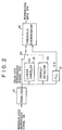
- a first embodiment having a circuit constitution of Fig. 2 is contrived by combining the simplest of the fundamental circuits mentioned above.
- the digital VTR of Fig. 2 comprises a magnetic head 4, a rotary transformer 6, a reproduction amplifier 8 (all not shown), a reproduction equalizer 10, a PLL 12 and a threshold discriminator 14.
- the digital VTR further includes a linear canceller 18, a dropout detector 20 and a switch 24 which are connected in parallel to the PLL 12.
- the linear canceller 18 is disposed next to the equalizer 10 in the digital VTR, and the output of the equalizer 10 is discriminated either directly in the absence of any dropout or after being passed through the linear canceller 18 in the presence of any dropout, whereby errors derived from the dropout are reduced.
- the linear canceller 18 serves as an additional equalizer sufficiently to compensate for the characteristic deterioration in the vicinity of the dropout.
- the dropout detector 20 has a function of selectively changing the switch 24 by detecting that the amplitude of the equalized reproduced signal S10 has become smaller continuously than a preset value for a predetermined period of time.
- Fig. 3 shows a digital VTR as a second embodiment of the present invention.
- This digital VTR comprises a magnetic head 4, a rotary transformer 6, a reproduction amplifier 8 (all not shown), a reproduction equalizer 10, a PLL 12, an A-D converter 26, a digital linear canceller 28, a digital dropout detector 30, a switch 32 and a threshold discriminator 14.
- the linear canceller 18 can be realized with extreme facility by the use of a digital circuit. Therefore, the circuit configuration is so arranged that the equalized reproduced signal S10 obtained from the equalizer 10 is digitized by the A-D converter 26 in accordance with the sampling clock signal S12 outputted from the PLL 12, and each of the digital linear canceller 28 functionally equivalent to the linear canceller 18 and the digital dropout detector 30 functionally equivalent to the dropout detector 20 is composed of a digital circuit.
- a preset value is added to the reproduced signal in accordance with the result of discriminating the preceding and following bits, and another discrimination is executed.
- Cn coefficient to following bit
- Cb coefficient to preceding bit
- A'[k] result of kth rediscrimination (1 or 0)
- Fig. 4 graphically shows the result of verifying the operation in the digital VTR of Fig. 3 by using the data obtained through a computer 40 (not shown) which is disposed next to a threshold discriminator 14 (not shown) in the digital VTR of Fig. 3 as in the aforementioned constitution of Fig. 5.
- the embodiments mentioned above represent examples of using a magnetic tape 2 as a recording medium.
- the recording medium is not limited to such magnetic tape alone, and any other recording medium such as a magnetic disk is applicable as well.
- a video signal is recorded as an exemplary digital signal on the recording medium in the description
- the apparatus of the invention is usable for reproduction of any other digital signal in addition to the video signal mentioned.
Landscapes
- Engineering & Computer Science (AREA)
- Signal Processing (AREA)
- Multimedia (AREA)
- Signal Processing For Digital Recording And Reproducing (AREA)
- Digital Magnetic Recording (AREA)
Applications Claiming Priority (2)
| Application Number | Priority Date | Filing Date | Title |
|---|---|---|---|
| JP317851/92 | 1992-11-02 | ||
| JP4317851A JPH06150216A (ja) | 1992-11-02 | 1992-11-02 | ディジタル信号再生方法とその装置 |
Publications (3)
| Publication Number | Publication Date |
|---|---|
| EP0596626A2 true EP0596626A2 (fr) | 1994-05-11 |
| EP0596626A3 EP0596626A3 (fr) | 1994-11-23 |
| EP0596626B1 EP0596626B1 (fr) | 1998-06-03 |
Family
ID=18092767
Family Applications (1)
| Application Number | Title | Priority Date | Filing Date |
|---|---|---|---|
| EP93308373A Expired - Lifetime EP0596626B1 (fr) | 1992-11-02 | 1993-10-21 | Appareil de reproductions de signaux digitaux |
Country Status (4)
| Country | Link |
|---|---|
| US (1) | US5469306A (fr) |
| EP (1) | EP0596626B1 (fr) |
| JP (1) | JPH06150216A (fr) |
| DE (1) | DE69318929T2 (fr) |
Cited By (1)
| Publication number | Priority date | Publication date | Assignee | Title |
|---|---|---|---|---|
| GB2377316A (en) * | 2001-07-07 | 2003-01-08 | Hewlett Packard Co | Drop-out management in a data read channel |
Families Citing this family (7)
| Publication number | Priority date | Publication date | Assignee | Title |
|---|---|---|---|---|
| KR0183704B1 (ko) * | 1994-12-19 | 1999-04-15 | 김광호 | 디지탈 기록/재생시스템에 있어서 데이타 검출방법 및 장치 |
| US6172827B1 (en) | 1995-09-30 | 2001-01-09 | Samsung Electronics Co., Ltd. | Device for recording signal so as to facilitate effective dropout compensation |
| US6310660B1 (en) | 1998-03-18 | 2001-10-30 | Sony Corporation | Video signal dropout detector |
| US6304400B1 (en) | 1999-03-08 | 2001-10-16 | Storage Technology Corporation | Signal dropout compensation |
| US8027378B1 (en) * | 2006-06-29 | 2011-09-27 | Marvell International Ltd. | Circuits, architectures, apparatuses, systems, algorithms and methods and software for amplitude drop detection |
| JP5333517B2 (ja) * | 2011-05-26 | 2013-11-06 | ヤマハ株式会社 | データ処理装置およびプログラム |
| CN119984349B (zh) * | 2025-01-16 | 2025-10-28 | 重庆理工大学 | 基于鉴幅式旋转变压器的数字角度解算系统和方法 |
Family Cites Families (10)
| Publication number | Priority date | Publication date | Assignee | Title |
|---|---|---|---|---|
| JPS58211312A (ja) * | 1982-05-31 | 1983-12-08 | Akai Electric Co Ltd | ビデオpcm再生装置におけるドロツプアウト補償回路 |
| JPS639005A (ja) * | 1986-06-30 | 1988-01-14 | Toshiba Corp | 磁気記録再生装置 |
| JPS63305686A (ja) * | 1987-06-08 | 1988-12-13 | Sony Corp | ドロップアウト検出回路 |
| JP2509626B2 (ja) * | 1987-07-03 | 1996-06-26 | 株式会社東芝 | 磁気記録再生装置 |
| JPH01229516A (ja) * | 1988-03-10 | 1989-09-13 | Sony Corp | 自動等化器 |
| US5177734A (en) * | 1988-05-02 | 1993-01-05 | Itt Corporation | Multirate wire line modem apparatus |
| JP2610954B2 (ja) * | 1988-08-24 | 1997-05-14 | 富士通株式会社 | イコライザ特性補正方式 |
| JPH0821164B2 (ja) * | 1990-01-09 | 1996-03-04 | 富士通株式会社 | 磁気テープ再生回路 |
| JP2746721B2 (ja) * | 1990-03-23 | 1998-05-06 | 松下電器産業株式会社 | ディジタル信号記録再生装置 |
| US5220466A (en) * | 1991-05-21 | 1993-06-15 | International Business Machines Corporation | Method and apparatus for digital filter control in a partial-response maximum-likelihood disk drive system |
-
1992
- 1992-11-02 JP JP4317851A patent/JPH06150216A/ja active Pending
-
1993
- 1993-10-21 EP EP93308373A patent/EP0596626B1/fr not_active Expired - Lifetime
- 1993-10-21 DE DE69318929T patent/DE69318929T2/de not_active Expired - Fee Related
- 1993-10-22 US US08/139,750 patent/US5469306A/en not_active Expired - Fee Related
Cited By (3)
| Publication number | Priority date | Publication date | Assignee | Title |
|---|---|---|---|---|
| GB2377316A (en) * | 2001-07-07 | 2003-01-08 | Hewlett Packard Co | Drop-out management in a data read channel |
| GB2378568A (en) * | 2001-07-07 | 2003-02-12 | Hewlett Packard Co | Drop-out management in a data read channel |
| GB2378568B (en) * | 2001-07-07 | 2004-08-25 | Hewlett Packard Co | Drop-out management system and method |
Also Published As
| Publication number | Publication date |
|---|---|
| US5469306A (en) | 1995-11-21 |
| EP0596626A3 (fr) | 1994-11-23 |
| JPH06150216A (ja) | 1994-05-31 |
| DE69318929T2 (de) | 1998-10-01 |
| DE69318929D1 (de) | 1998-07-09 |
| EP0596626B1 (fr) | 1998-06-03 |
Similar Documents
| Publication | Publication Date | Title |
|---|---|---|
| EP0831480B1 (fr) | Appareil et procédé de traitement d'information | |
| GB2104756A (en) | Automatic threshold tracking system | |
| EP0681771A1 (fr) | Circuit a commande de gain pour l'echantillonnage synchrone de formes d'onde | |
| US5625632A (en) | Magnetic disk drive including a data discrimination apparatus capable of correcting signal waveform distortion due to intersymbol interference | |
| US5469306A (en) | Digital signal reproducing method and apparatus | |
| US5436771A (en) | Apparatus for correcting a pick-up signal of a digital magnetic recording and reproducing apparatus | |
| US20020012308A1 (en) | Information reproducing apparatus and phase lock control apparatus | |
| US4531165A (en) | Automatic amplitude equalizer based upon monitoring of channel power loss | |
| US5615060A (en) | Automatic clock signal phase adjusting circuit utilizing level detector and pattern detector | |
| EP1040473B1 (fr) | Effacement adaptatif et selectif des interferences intersymboles d'un canal de lecture dans les technologies des memoires | |
| US6549352B1 (en) | Signal processing apparatus utilizing a partial response method, and signal processing method, information recording apparatus, and information reproduction apparatus therefore | |
| JP2763454B2 (ja) | データ検出装置 | |
| KR100192236B1 (ko) | 디지탈 자기기록 재생장치 | |
| KR101044767B1 (ko) | Rf 신호 디지털 부분 응답 비대칭 보상 | |
| US20040250194A1 (en) | Method for bit recovery in an asymmetric data channel | |
| JP3543556B2 (ja) | ディジタル同期分離装置 | |
| JP3430831B2 (ja) | 雑音除去回路 | |
| JP3053963B2 (ja) | 磁気記録再生装置 | |
| JPH0528655A (ja) | データ再生装置 | |
| JP2001291327A (ja) | ディジタル信号再生装置 | |
| JPH05274610A (ja) | ハイファイ音声付きvtrの記録電流設定回路 | |
| JPS63113981A (ja) | デジタル信号検出回路 | |
| JPH04268255A (ja) | 記憶装置の再生信号レベル判定器 | |
| JPH08161838A (ja) | データ記録再生装置 | |
| JPH05210913A (ja) | データ再生回路及びこれを用いたデータ記憶装置 |
Legal Events
| Date | Code | Title | Description |
|---|---|---|---|
| PUAI | Public reference made under article 153(3) epc to a published international application that has entered the european phase |
Free format text: ORIGINAL CODE: 0009012 |
|
| AK | Designated contracting states |
Kind code of ref document: A2 Designated state(s): DE FR GB |
|
| PUAL | Search report despatched |
Free format text: ORIGINAL CODE: 0009013 |
|
| AK | Designated contracting states |
Kind code of ref document: A3 Designated state(s): DE FR GB |
|
| 17P | Request for examination filed |
Effective date: 19950420 |
|
| 17Q | First examination report despatched |
Effective date: 19960731 |
|
| GRAG | Despatch of communication of intention to grant |
Free format text: ORIGINAL CODE: EPIDOS AGRA |
|
| GRAG | Despatch of communication of intention to grant |
Free format text: ORIGINAL CODE: EPIDOS AGRA |
|
| GRAH | Despatch of communication of intention to grant a patent |
Free format text: ORIGINAL CODE: EPIDOS IGRA |
|
| GRAH | Despatch of communication of intention to grant a patent |
Free format text: ORIGINAL CODE: EPIDOS IGRA |
|
| GRAA | (expected) grant |
Free format text: ORIGINAL CODE: 0009210 |
|
| AK | Designated contracting states |
Kind code of ref document: B1 Designated state(s): DE FR GB |
|
| REF | Corresponds to: |
Ref document number: 69318929 Country of ref document: DE Date of ref document: 19980709 |
|
| ET | Fr: translation filed | ||
| PLBE | No opposition filed within time limit |
Free format text: ORIGINAL CODE: 0009261 |
|
| 26N | No opposition filed | ||
| PGFP | Annual fee paid to national office [announced via postgrant information from national office to epo] |
Ref country code: FR Payment date: 20001010 Year of fee payment: 8 |
|
| PGFP | Annual fee paid to national office [announced via postgrant information from national office to epo] |
Ref country code: DE Payment date: 20001016 Year of fee payment: 8 |
|
| PGFP | Annual fee paid to national office [announced via postgrant information from national office to epo] |
Ref country code: GB Payment date: 20001018 Year of fee payment: 8 |
|
| PG25 | Lapsed in a contracting state [announced via postgrant information from national office to epo] |
Ref country code: GB Free format text: LAPSE BECAUSE OF NON-PAYMENT OF DUE FEES Effective date: 20011021 |
|
| REG | Reference to a national code |
Ref country code: GB Ref legal event code: IF02 |
|
| GBPC | Gb: european patent ceased through non-payment of renewal fee |
Effective date: 20011021 |
|
| PG25 | Lapsed in a contracting state [announced via postgrant information from national office to epo] |
Ref country code: FR Free format text: LAPSE BECAUSE OF NON-PAYMENT OF DUE FEES Effective date: 20020628 |
|
| PG25 | Lapsed in a contracting state [announced via postgrant information from national office to epo] |
Ref country code: DE Free format text: LAPSE BECAUSE OF NON-PAYMENT OF DUE FEES Effective date: 20020702 |
|
| REG | Reference to a national code |
Ref country code: FR Ref legal event code: ST |