EP0596638A1 - Système d'interconnexion à tolérance réduite - Google Patents
Système d'interconnexion à tolérance réduite Download PDFInfo
- Publication number
- EP0596638A1 EP0596638A1 EP93308507A EP93308507A EP0596638A1 EP 0596638 A1 EP0596638 A1 EP 0596638A1 EP 93308507 A EP93308507 A EP 93308507A EP 93308507 A EP93308507 A EP 93308507A EP 0596638 A1 EP0596638 A1 EP 0596638A1
- Authority
- EP
- European Patent Office
- Prior art keywords
- backplane
- enclosure
- recesses
- center portion
- end portions
- Prior art date
- Legal status (The legal status is an assumption and is not a legal conclusion. Google has not performed a legal analysis and makes no representation as to the accuracy of the status listed.)
- Withdrawn
Links
Images




Classifications
-
- H—ELECTRICITY
- H05—ELECTRIC TECHNIQUES NOT OTHERWISE PROVIDED FOR
- H05K—PRINTED CIRCUITS; CASINGS OR CONSTRUCTIONAL DETAILS OF ELECTRIC APPARATUS; MANUFACTURE OF ASSEMBLAGES OF ELECTRICAL COMPONENTS
- H05K7/00—Constructional details common to different types of electric apparatus
- H05K7/14—Mounting supporting structure in casing or on frame or rack
- H05K7/1422—Printed circuit boards receptacles, e.g. stacked structures, electronic circuit modules or box like frames
- H05K7/1424—Card cages
- H05K7/1425—Card cages of standardised dimensions, e.g. 19"-subrack
Definitions
- This invention relates generally to blind mate interconnect systems, and particularly to a reduced tolerance enclosure providing simple, low cost blind mate interconnections.
- Blind mate interconnect systems provide automatic mating between connector elements on a backplane and connector elements on hardware modules, such as storage devices, when the modules are installed in an enclosure.
- the connection is typically made in an interior region of the enclosure, which is usually not easily accessible.
- One difficulty resulting from the use of a blind mate interconnect is assuring that the two mating connector elements are properly aligned so that the connection will be reliably made, especially in an environment requiring hot swap of components such as disk drives.
- the enclosure consists of enclosure sections holding a backplane containing connectors with which the module connectors mate on installation.
- the backplane must be installed in the enclosure in such a way as to guarantee a proper blind mate interconnection when a module is installed.
- mechanical tolerances involved in constructing the typical enclosure and backplane assembly are larger than that which can guarantee a proper installation without special hardware or post-construction adjustments to the positioning of the backplane within the enclosure.
- the present invention provides a new and improved enclosure in which a blind mate interconnection of a hardware module with the backplane may be guaranteed without the need for assembly fixtures or floating connectors.
- the invention in its broad form resides in a connector enclosure as recited in claim 1 and a method of producing an enclosure as recited in claim 10.
- the enclosure includes identical, interchangeable enclosure sections and requires no screws or other hardware for securing the backplane, thus further reducing the cost and complexity of the system.
- Described hereinafter is an apparatus and method for producing a simple, low cost, reduced tolerance enclosure in which a blind mate interconnect between modules and the backplane may be guaranteed without the need for assembly fixtures or floating connectors.
- a preferred embodiment provides an enclosure including two matching enclosure sections for aligning and securing a backplane.
- the backplane has spaced apart recesses on opposing edges.
- Each enclosure section includes alignment protrusions spaced apart to engage the backplane recesses. These protrusions have curved apex regions and a height greater than the depth of the backplane recesses.
- Means for latching the enclosure sections together are provided, the enclosure sections being effective such that when the enclosure sections are closed around the backplane, the protrusions from the enclosure sections are urged against the recesses on the backplane. The resulting multi-point-of-contact interference fit between the backplane recesses and alignment protrusions automatically centers the backplane in the enclosure.
- the backplane recesses and the protrusions both have arcuate contours, the apex regions of the protrusions being more arcuate than the bottoms of the recesses.
- the recesses in the backplane are created by drilling holes in a panel from which the backplanes are routed.
- the drilled holes result in arcuate recesses on the backplane edge.
- each enclosure section is constructed of injection molded plastic. The molding process is normally controlled such that the center portion of each enclosure section is flat to convex. The center portion also contains module guide channels for guiding the modules to the backplane connectors on installation.
- FIG 1 there is shown a fully loaded enclosure 10 embodying the principles of the invention, in which modules 12, which may be for example storage devices such as disk drives, are connected to a backplane 14 (see Figure 2).
- the modules 12 are connected to the backplane 14 by means of a blind mate interconnection.
- FIG 2 shows an exploded view of the enclosure 10 of Figure 1, showing a backplane 14 to which the modules 12 are electrically connected during operation.
- the backplane 14 includes recesses 15 spaced along opposing edges.
- the enclosure 10 includes enclosure sections 16 and 18, each of which as shown include a center portion 20 and end portions 22.
- Each of the enclosure sections 16 and 18 further includes spaced apart alignment protrusions 23, one of which is shown on the enclosure section 18 of Figure 2, for engaging the backplane recesses 15.
- Means for latching the enclosure sections 16 and 18 together around the backplane are included on the end portions 22, here shown as conventional alternating male and female snap latches 24 and 25 respectively.
- the enclosure sections 16 and 18 are effective such that when the enclosure sections 16 and 18 are closed around the backplane 14, the protrusions 23 are urged against the recesses 15, creating an interference fit for accurately positioning and holding the backplane 14 in place within the enclosure 10.
- module guide rails 26 are included on the interior portion of the center portion 20 of each of enclosure sections 16 and 18 for guiding the modules 12 towards the backplane 14 to mate with the backplane connectors. Also included near an edge of the center portion 20 of each of the enclosure sections 16 and 18 is a backplane guide channel 28, extending transversely from the module guide rails 26.
- alignment protrusions 23 are spaced apart.
- the alignment protrusions 23 are spaced to engage the recesses on the backplane 14 in the assembled enclosure 10. As shown, the protrusions 23 have curved apex regions and a height greater than the depth of the recesses 15 on the backplane 14.
- the backplane 14 is positioned within the backplane guide channel 28 of each enclosure section 16 and 18 such that the alignment protrusions 23 engage the bottoms of the backplane recesses 15. As shown, the enclosure sections 16 and 18 are held together by snap latches 24. The enclosure sections 16 and 18 are effective such that the backplane 14 is held in place by the urging of the alignment protrusions 23 of the enclosure sections 16 and 18 against the recesses 15 of the backplane 14.
- Figure 3 is an exploded view of a portion of one of the enclosure sections 16 or 18 and the backplane 14 of Figure 1, showing in more detail the backplane guide channel 28 and alignment protrusions 23, the module guide rails 26, and the backplane recesses 15.
- the recesses 15 have a generally arcuate contour.
- the apex regions of the alignment protrusions 23 are also arcuate, and are more arcuate than the contact surfaces of the recesses 15.
- the alignment protrusions 23 have a height greater than the depth of the recesses 15. This dimensioning guarantees that, when the enclosure 10 is assembled, the effective pressure points of contact between the backplane 14 and the enclosure sections 16 and 18 occur between the shelf alignment protrusions 23 and the backplane recesses 15, as is more clearly detailed by the dotted lines in Figure 3, which represent the backplane 14 position relative to the enclosure section 18 when installed. This multi-point-of-contact interference fit serves to accurately center the backplane 14 between the enclosure sections 16 and 18.
- the urging of the alignment protrusions 23 against the backplane recesses 15 has been advantageously provided by dimensional characteristics of the various parts.
- the dimension between the end portions 22 and the apex of the protrusions 23, designated 'a' in Figure 4 is shown as slightly less than the one-half widthwise dimension between the backplane 14 and the bottom of the recess 15, designated 'b' in Figure 4. This dimensional difference requires that the enclosure sections 16 and 18 be forced about the backplane 14, providing the interference fit.
- the center portion 20 of each of the enclosure sections 16 and 18 is flexible and may be of a flat to convex contour. In the embodiment shown in the Figures, this construction allows the enclosure sections 16 and 18 be bent to some extent around the backplane 14 in order to fully engage the latching means 24.
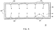
- the enclosure sections 16 and 18 serve to force alignment protrusions 23 towards the bottom center of the recesses 15 in the backplane 14. Moreover, as shown, the protrusions 23 and recesses 15 are aligned equidistantly along the length of the assembly 10, so equal and opposing forces are exerted by the shelf protrusions 23 against the backplane 14 at contact points within recesses 15, shown by the arrows in Figure 5.
- This interference fit between the enclosure sections 16 and 18 and the backplane 14 centers the backplane 14 vertically and horizontally between the enclosure sections 16 and 18. The backplane 14 is thus held firmly in position within the enclosure 10 without the need for screws or extra mounting hardware.
- backplane templates are used to drill and etch multiple backplanes on a panel 32.
- the recessions 15 are then created by drilling rows of drilled holes 34 under computer numerical control at precise locations on the panel, and then routed in a conventional manner, where the routing path crosses the drilled holes 34.
- Each resulting backplane 14 is then left with arcuate recessions 15, for example recesses that are quarter circle arcs, drilled along its edge.
- Another step in the method of producing the high tolerance enclosure 10 involves producing identical enclosure sections 16 and 18, and is accomplished by making the enclosure sections 16 and 18 as unitary injection molded plastic pieces of a suitable plastic, for example, a glass reinforced plastic sold by General Electric Company under the trade name LEXAN.
- a suitable plastic for example, a glass reinforced plastic sold by General Electric Company under the trade name LEXAN.
- protrusions 23 every 9.46mm (3.725 inches) starting 3.299mm (1.299 inches) from a reference edge.
- the apex of each protrusion 23 is spaced at 6.38 mm +/- 0.005mm (2.512 inches +/- .002 inches) from the end of the end portion 22 (shown as dimension 'a' of Figure 4), which is the contact point between the enclosure sections 16 and 18 when they are latched together, and thus the midpoint of the enclosure.
- the space between opposing recesses 15 on the backplane is positive to .016 inches greater than the space between opposing protrusions 23 on the enclosure sections 16 and 18.
- the radius of the apex of the protrusions 23 is .090 inches, as compared to the 3.2mm (.125 inch) radius of the recesses 15.
- Means for latching the end portions of the enclosure sections together are provided as part of the unitary molded enclosure section 16. While a variety of methods may be used, it has been convenient to utilize molded male and female snap latches 24 and 25, as can be seen in Figure 1. Each male latch 24 on one end portion 22 has a corresponding female latch 25 on the opposite end portion 22 at the same position, so that when two enclosure sections 16 and 18 are positioned to be latched together, the male latches 24 of the enclosure section 16 will engage the female latches 25 of enclosure section 18 and vice-versa.
- the resulting enclosure 10 has reduced tolerances over previous enclosures due to a combination of results of the described process.
- the contact points on backplane 14 for engaging enclosure sections 16 and 18 are drilled hole edges. Drilled holes are more tightly toleranced, on the order of thousandths of an inch, than routed edges, which are toleranced on the order of hundredths of an inch.
- the multi-point-of-contact interference fit which centers the backplane 14 between enclosure sections 16 and 18 results in much more accurate positioning of the backplane 14 than can be achieved by relying on screws through larger diameter, relatively loosely toleranced backplane holes.
- the flat to convex bow in the center portion 20 of each enclosure section 16 and 18 guarantees that an interference fit will occur.
- the enclosure sections 16 and 18 are produced of single unit injection molded plastic. Dimensions in the injection molded process may be very tightly controlled; thus, the module guide rails 26 are spaced very accurately from the alignment protrusions 23.
- FIG. 7 there is shown a double-height enclosure 40 including four enclosure sections; the outer enclosure sections 16 and 18 of Figure 1, and inner enclosure sections 44 and 46. All four enclosure sections 16, 18, 44, and 46 are manufactured according to the above described process.
- the two inner enclosure sections 44 and 46 further include slots 48 cut through their center portions at a location corresponding to the backplane channel 28 of outer enclosure sections 16 and 18 as shown in Figure 2.
- the two inner enclosure sections 44 and 46 are bolted together (not shown), and latched to the outer enclosure section 18.
- a double height backplane 50, including recesses 52 shown in Figure 8, is then inserted through the slots 48 such that the recesses 52 engage protrusions 23 as previously described.
- Outer enclosure section 16 is then latched around backplane 50, also such that protrusions 23 engage recesses 52. Again, an interference fit accurately positions and retains double-height backplane 50 within enclosure 40.
- This double-height enclosure 50 may be used, for example, for mounting disk drives which blind-mate with backplane connectors on the lower half of backplane 50, while also mounting card cages containing disk controller modules which blind-mate with backplane connectors on the top half of backplane 50. It is possible to add further inner enclosure sections like enclosure sections 44 and 46 for uses such as stacking multiple rows of disk drives.
Landscapes
- Engineering & Computer Science (AREA)
- Microelectronics & Electronic Packaging (AREA)
- Casings For Electric Apparatus (AREA)
- Mounting Of Printed Circuit Boards And The Like (AREA)
Applications Claiming Priority (2)
| Application Number | Priority Date | Filing Date | Title |
|---|---|---|---|
| US07/970,721 US5313369A (en) | 1992-11-03 | 1992-11-03 | Reduced tolerance interconnect system |
| US970721 | 1992-11-03 |
Publications (1)
| Publication Number | Publication Date |
|---|---|
| EP0596638A1 true EP0596638A1 (fr) | 1994-05-11 |
Family
ID=25517397
Family Applications (1)
| Application Number | Title | Priority Date | Filing Date |
|---|---|---|---|
| EP93308507A Withdrawn EP0596638A1 (fr) | 1992-11-03 | 1993-10-26 | Système d'interconnexion à tolérance réduite |
Country Status (2)
| Country | Link |
|---|---|
| US (1) | US5313369A (fr) |
| EP (1) | EP0596638A1 (fr) |
Cited By (1)
| Publication number | Priority date | Publication date | Assignee | Title |
|---|---|---|---|---|
| WO2013034434A3 (fr) * | 2011-09-05 | 2013-05-23 | Fujitsu Technology Solutions Intellectual Property Gmbh | Cage de montage pour ordinateur, pourvue d'un fond de panier, et procédé |
Families Citing this family (21)
| Publication number | Priority date | Publication date | Assignee | Title |
|---|---|---|---|---|
| EP0738102B1 (fr) * | 1995-04-12 | 1999-09-01 | Digital Equipment Corporation | Enceinte antistatique pour disques RAID |
| TW397272U (en) * | 1998-12-31 | 2000-07-01 | Hon Hai Prec Ind Co Ltd | Modular box for universal communication port |
| US6288902B1 (en) * | 1999-05-25 | 2001-09-11 | Hewlett-Packard Company | Modular data storage system for reducing mechanical shock and vibrations |
| US6256205B1 (en) * | 1999-12-29 | 2001-07-03 | Marconi Communications, Inc. | Fastenerless card cage for circuit cards |
| WO2001072173A1 (fr) * | 2000-03-25 | 2001-10-04 | Eurologic Systems | Boitier d'un systeme de stockage de donnees relatives au reseau |
| IES20010399A2 (en) * | 2000-05-16 | 2002-02-06 | Richmount Computers Ltd | A protocol for a power supply unit controller |
| US6832324B2 (en) * | 2000-05-16 | 2004-12-14 | Richmount Computers Limited | Method for providing a device communicating to a backplane the current status of an associated power supply unit connected to the backplane |
| IES20010398A2 (en) * | 2000-07-06 | 2002-02-06 | Richmount Computers Ltd | Improved power supply unit controller |
| IES20010396A2 (en) * | 2000-07-06 | 2002-02-06 | Richmount Computers Ltd | Fibre channel diagnostics in a storage enclosure |
| IES20010395A2 (en) * | 2000-07-26 | 2002-02-06 | Richmount Computers Ltd | Crosspoint switch for a fibre channel arbitrated loop |
| US6975590B2 (en) * | 2000-09-07 | 2005-12-13 | Eurologic Systems Limited | Fiber-channel arbitrated-loop split loop operation |
| IES20010611A2 (en) * | 2001-03-08 | 2002-09-18 | Richmount Computers Ltd | Distributed lock management chip |
| IES20010610A2 (en) * | 2001-03-08 | 2002-09-18 | Richmount Computers Ltd | Reset facility for redundant processor using a fibre channel loop |
| IES20010783A2 (en) * | 2001-04-26 | 2002-09-18 | Richmount Computers Ltd | Data storage apparatus |
| US7089345B1 (en) | 2002-04-23 | 2006-08-08 | Adaptec, Inc. | Method and apparatus for dual porting a single port serial ATA disk drive |
| USD494578S1 (en) | 2002-06-18 | 2004-08-17 | Sun Microsystems, Inc. | Computer equipment |
| USD481384S1 (en) | 2002-11-14 | 2003-10-28 | International Business Machines Corporation | Server module enclosure |
| US7193863B2 (en) * | 2005-01-28 | 2007-03-20 | Honeywell International Inc. | Electronics packaging assembly with parallel circuit boards and a vibration stiffener |
| US8760878B2 (en) | 2010-08-17 | 2014-06-24 | Rockwell Automation Technologies, Inc. | Floating circuit board alignment |
| US9214194B2 (en) * | 2013-03-01 | 2015-12-15 | Greentec-Usa, Inc. | External drive chassis storage array |
| CN118739786A (zh) * | 2023-03-31 | 2024-10-01 | 台达电子工业股份有限公司 | 并联式模块驱动器 |
Citations (2)
| Publication number | Priority date | Publication date | Assignee | Title |
|---|---|---|---|---|
| US4232356A (en) * | 1979-02-07 | 1980-11-04 | Burroughs Corporation | Logic card frame |
| US5023754A (en) * | 1990-01-19 | 1991-06-11 | International Business Machines Corporation | Double-sided backplane assembly |
Family Cites Families (9)
| Publication number | Priority date | Publication date | Assignee | Title |
|---|---|---|---|---|
| US4353614A (en) * | 1980-03-14 | 1982-10-12 | Western Electric Company, Inc. | Unitary molded plastic connector plug support member |
| FR2502447A1 (fr) * | 1981-03-19 | 1982-09-24 | Atomelec | Boitier destine a des montages electroniques ou electriques |
| DE3323604A1 (de) * | 1982-01-19 | 1985-01-03 | Siemens AG, 1000 Berlin und 8000 München | Gehaeuse fuer eine elektrische schaltungsanordnung |
| FR2521814B1 (fr) * | 1982-02-16 | 1985-09-27 | Transrack | Bac pour cartes de circuits, destine notamment aux coffrets et baies d'appareillages electroniques |
| US4405972A (en) * | 1982-03-08 | 1983-09-20 | Burroughs Corporation | Clamp device for retaining printed circuit boards under high shock conditions |
| US4652969A (en) * | 1985-07-05 | 1987-03-24 | Racal Data Communications Inc. | Secure universal housing arrangement for enclosing electronic circuits |
| US4878153A (en) * | 1988-05-23 | 1989-10-31 | Rockwell International Corporation | Electronic shelf assembly |
| GB2219693B (en) * | 1988-06-10 | 1992-09-02 | Schlumberger Electronics | Case structure |
| US5128830A (en) * | 1990-07-02 | 1992-07-07 | Digital Equipment Corporation | Integrated installation assembly with self aligning connector |
-
1992
- 1992-11-03 US US07/970,721 patent/US5313369A/en not_active Expired - Lifetime
-
1993
- 1993-10-26 EP EP93308507A patent/EP0596638A1/fr not_active Withdrawn
Patent Citations (2)
| Publication number | Priority date | Publication date | Assignee | Title |
|---|---|---|---|---|
| US4232356A (en) * | 1979-02-07 | 1980-11-04 | Burroughs Corporation | Logic card frame |
| US5023754A (en) * | 1990-01-19 | 1991-06-11 | International Business Machines Corporation | Double-sided backplane assembly |
Non-Patent Citations (1)
| Title |
|---|
| "Card alignment and location system using high I/O count connectors", IBM TECHNICAL DISCLOSURE BULLETIN., vol. 32, no. 12, May 1990 (1990-05-01), NEW YORK US, pages 10 - 13, XP000105051 * |
Cited By (1)
| Publication number | Priority date | Publication date | Assignee | Title |
|---|---|---|---|---|
| WO2013034434A3 (fr) * | 2011-09-05 | 2013-05-23 | Fujitsu Technology Solutions Intellectual Property Gmbh | Cage de montage pour ordinateur, pourvue d'un fond de panier, et procédé |
Also Published As
| Publication number | Publication date |
|---|---|
| US5313369A (en) | 1994-05-17 |
Similar Documents
| Publication | Publication Date | Title |
|---|---|---|
| US5313369A (en) | Reduced tolerance interconnect system | |
| US5580283A (en) | Electrical connector having terminal modules | |
| US6935868B1 (en) | Adjustable-width, dual-connector card module | |
| US6234817B1 (en) | Blind-mate, floatable connectors assembly | |
| US5124886A (en) | Drive canister mounting module | |
| US5184961A (en) | Modular connector frame | |
| US11437746B2 (en) | Board-end connector and wire-end connector | |
| US5545051A (en) | Board to board matable assembly | |
| US5128830A (en) | Integrated installation assembly with self aligning connector | |
| US6195262B1 (en) | Low profile computer or communications network interconnecting device and housing therefor | |
| KR920005464B1 (ko) | 시스템 케이블 조립체 및 부품 패키징 | |
| EP0248949A2 (fr) | Plateau support de carte de circuit | |
| CN1013728B (zh) | 三步自定位结构 | |
| US5774343A (en) | Hinged front panel assembly for circuit cards | |
| JP2005536831A (ja) | 複数のプロセッサを収容するシャシ装置で使用する単純構造電力及びデータコネクタ | |
| US5642264A (en) | Apparatus for supporting circuit cards in slot locations | |
| US5172306A (en) | Adaptive card mounting system | |
| US4398779A (en) | Keying apparatus for interconnecting electrical components | |
| US5358413A (en) | Right-angle board-mountable electrical connector with precision terminal positioning | |
| US12237615B2 (en) | MUTOA and quad floating connector | |
| JP2003142854A (ja) | 密な間隔でプリント回路カードを挿入するためのガイド構造 | |
| US6241539B1 (en) | Connector driving apparatus for driving a plurality of connectors relatively to a plurality of mating connectors | |
| TW202406239A (zh) | 浮動電連接器 | |
| US6000954A (en) | Two piece pin connector | |
| GB2243247A (en) | Printed circuit board assemblies |
Legal Events
| Date | Code | Title | Description |
|---|---|---|---|
| PUAI | Public reference made under article 153(3) epc to a published international application that has entered the european phase |
Free format text: ORIGINAL CODE: 0009012 |
|
| AK | Designated contracting states |
Kind code of ref document: A1 Designated state(s): DE FR GB IT |
|
| 17P | Request for examination filed |
Effective date: 19940627 |
|
| 17Q | First examination report despatched |
Effective date: 19950310 |
|
| 18W | Application withdrawn |
Withdrawal date: 19950522 |