EP0596669A1 - Schraubenzieher - Google Patents
Schraubenzieher Download PDFInfo
- Publication number
- EP0596669A1 EP0596669A1 EP93308673A EP93308673A EP0596669A1 EP 0596669 A1 EP0596669 A1 EP 0596669A1 EP 93308673 A EP93308673 A EP 93308673A EP 93308673 A EP93308673 A EP 93308673A EP 0596669 A1 EP0596669 A1 EP 0596669A1
- Authority
- EP
- European Patent Office
- Prior art keywords
- screwdriver
- sleeve device
- adaptor
- fitment
- shaft portion
- Prior art date
- Legal status (The legal status is an assumption and is not a legal conclusion. Google has not performed a legal analysis and makes no representation as to the accuracy of the status listed.)
- Granted
Links
Images


Classifications
-
- B—PERFORMING OPERATIONS; TRANSPORTING
- B25—HAND TOOLS; PORTABLE POWER-DRIVEN TOOLS; MANIPULATORS
- B25B—TOOLS OR BENCH DEVICES NOT OTHERWISE PROVIDED FOR, FOR FASTENING, CONNECTING, DISENGAGING OR HOLDING
- B25B23/00—Details of, or accessories for, spanners, wrenches, screwdrivers
- B25B23/02—Arrangements for handling screws or nuts
- B25B23/08—Arrangements for handling screws or nuts for holding or positioning screw or nut prior to or during its rotation
- B25B23/10—Arrangements for handling screws or nuts for holding or positioning screw or nut prior to or during its rotation using mechanical gripping means
- B25B23/101—Arrangements for handling screws or nuts for holding or positioning screw or nut prior to or during its rotation using mechanical gripping means for hand-driven screw-drivers
-
- B—PERFORMING OPERATIONS; TRANSPORTING
- B25—HAND TOOLS; PORTABLE POWER-DRIVEN TOOLS; MANIPULATORS
- B25B—TOOLS OR BENCH DEVICES NOT OTHERWISE PROVIDED FOR, FOR FASTENING, CONNECTING, DISENGAGING OR HOLDING
- B25B23/00—Details of, or accessories for, spanners, wrenches, screwdrivers
- B25B23/005—Screw guiding means
-
- B—PERFORMING OPERATIONS; TRANSPORTING
- B25—HAND TOOLS; PORTABLE POWER-DRIVEN TOOLS; MANIPULATORS
- B25B—TOOLS OR BENCH DEVICES NOT OTHERWISE PROVIDED FOR, FOR FASTENING, CONNECTING, DISENGAGING OR HOLDING
- B25B23/00—Details of, or accessories for, spanners, wrenches, screwdrivers
- B25B23/02—Arrangements for handling screws or nuts
- B25B23/08—Arrangements for handling screws or nuts for holding or positioning screw or nut prior to or during its rotation
- B25B23/12—Arrangements for handling screws or nuts for holding or positioning screw or nut prior to or during its rotation using magnetic means
-
- B—PERFORMING OPERATIONS; TRANSPORTING
- B25—HAND TOOLS; PORTABLE POWER-DRIVEN TOOLS; MANIPULATORS
- B25G—HANDLES FOR HAND IMPLEMENTS
- B25G1/00—Handle constructions
- B25G1/08—Handle constructions with provision for storing tool elements
- B25G1/085—Handle constructions with provision for storing tool elements for screwdrivers, wrenches or spanners
Definitions
- the invention relates to screwdrivers, in particular, although not exclusively, to screwdrivers for driving single slotted screws.
- a particular hazard when driving screws of the single slotted variety is that of the blade of the screwdriver slipping off the screw head and scoring the surface of or alongside the member (possibly an expensive hardwood door or the like) into which the screw is being driven. This hazard is much reduced when using screwdrivers of the "Phillips" type to drive screws having a cruciform type of driving slot, but is not entirely eliminated.
- a further problem is that, unless a pilot hole has either been drilled or produced by a bradawl for example, a screw cannot easily be started in its required location because any substantial axial force applied to the screw by the screwdriver tends to tilt the screw out of line and to cause the disengagement of the screwdriver and screw.
- Sleeve devices have in the past been provided for fitment on screwdriver blades. Such devices have, however, been of only limited assistance in that the screwdriver blade may have been located centrally of the screw head by such a sleeve device but the starting of the screw has not been facilitated thereby.
- the invention as claimed is intended to provide a remedy. It solves the problem of how to prevent the blade of a screwdriver from slipping off a screw head and of how to ensure that the screw is not tilted out of line by axial force applied to the screw by a screwdriver.
- the advantages offered by the invention are, mainly, that it provides a means whereby, during the driving of a screw a screwdriver can be prevented from slipping off the screw and can be driven with substantial axial force from the start.
- the invention in addition enables a screwdriver to be driven two handed when the screw is to be finally tightened.
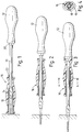
- the screwdriver there illustrated has a cylindrical shaft portion 10 with a handle 12 at one end and blade portion 14 at the other.
- a sleeve device is freely rotatable on the shaft portion 10.
- Said sleeve device made mainly of a synthetic plastics material, has a metal liner 18 which extends rather more than halfway along the length of the device from its end remote from the handle.
- the sleeve is in fact somewhat longer than a wood screw which is shown in chain-dotted lines within the front end of the sleeve device, the screw being of average length having regard to its diameter.
- the bore of the sleeve device is a stepped bore so that said sleeve device is held captive on the shaft portion by the widening of the blade.
- the underside of the handle 12 is provided with a hexagonal driving nut portion 20 and the rear end of the sleeve device has a hexagonal socket 22 in which said nut portion can be engaged.
- the screwdriver is shown in Figure 1 in a first mode of use, that is to say, with the sleeve in a forward position in which it prevents the screwdriver blade from slipping sideways out of engagement with the screw head.
- the sleeve device shrouds the full length of the screw and extends a somewhat longer distance along the shaft portion of the screwdriver, the screw is supported against any tendency to tilt. Consequently, despite the fact that it is not being started in a pilot hole drilled or formed by a bradawl for example, the screw can be driven hard with substantial axial force without fear of the screw tilting. The average time required to drive each screw can therefore be expected to be much reduced.
- the screwdriver is shown in a second mode of use, the sleeve device having been relocated to a position intermediate the ends of the shaft portion where it can be used as a spinner.
- the sleeve device can be held by the user to provide a steady for the screwdriver blade.
- the screwdriver is shown in a third mode of use when the screw has been almost completely driven into position, that is to say with the sleeve device re-located so that its rear end engages the handle non-rotatably.
- the user of the screwdriver can thus use both hands for extra torque to drive the screw home.
- the sleeve device can be used with a segmental action.
- the sleeve device is of non-circular external shape so as to facilitate the way in which it can be grasped and turned, it can be angularly re-located with the handle after each small turning movement to suit the personal preference of the user. (The screwdriver can of course be used in reverse, that is to say when unscrewing).
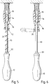
- FIG 5 this illustrates a possible modification of the screwdriver of Figures 1 to 4, the modification being the provision of a coil compression spring 24 for urging the sleeve device away from the handle 12.
- the spring 24 embraces the shaft portion 10 of the screwdriver; at one end it abuts against the sleeve device and at its other end it abuts against the driving nut portion 20 at the underside of the handle.
- this modified form of screwdriver can be used one-handed to insert a screw in an overhead location where this could only otherwise be done with great difficulty (as for example by drilling a pilot hole and starting the screw by hand before using the screwdriver).
- the spring is a relatively weak spring. That is to say, although it can support the weight of the sleeve device the spring is quite easily compressed by the user as the screw is screwed into position. The spring can be removed when the sleeve device is to be brought into engagement with the driving nut portion 20 at the underside of the handle, the sleeve device in this case not being captive on the shaft portion of the screwdriver.
- FIG. 6 there is illustrated the provision of means for producing a resistance to axial sliding of the sleeve device along the cylindrical shaft portion of the screwdriver, these means taking the form of a resilient clip element 26 which can be snap fitted on said shaft portion beneath the sleeve device.
- the sleeve device will have means located within its bore for acting very lightly against the cylindrical shaft portion of the screwdriver, this producing an initial resistance to axial sliding of said sleeve device, the fitment of said resilient clip element 26 on said shaft portion then providing a somewhat greater resistance to axial sliding of said sleeve device.
- FIG 7 there is illustrated a rather different embodiment of the invention, this being an adaptor unit for fitment to a screwdriver.
- the screwdriver to which the adaptor unit is shown being fitted in Figure 7 is a pump action spiral screwdriver but it will be understood that it could equally well be a motor driven screwdriver).
- the adaptor unit illustrated in Figure 7 has a cylindrical shaft portion 110 with a plug-in type adaptor spindle 112 at one end and an axial recess 114 at the other end for the reception of a selected one of a plurality of screwdriver bits 115.
- the shaft portion 110 has been magnetised to retain the ferrous screwdriver bit in position.
- a sleeve device, generally indicated 116, is freely rotatable on the shaft portion 110 and is of similar form to the sleeve device 16 of the first described embodiment, having a hexagonal socket 122 at its rear end which can be engaged with a hexagonal driving nut portion 120 formed adjacent the adaptor spindle 112 of the cylindrical shaft portion.
- the sleeve device of this embodiment can be used in a generally similar way to the sleeve device of the first described embodiment.
- said sleeve device can embrace the screwdriver bit and can contain a screw engaged by said screwdriver bit for the starting of the screw.
- the sleeve device can be used as a spinner for steadying the shaft portion 110 as the latter is rotationally driven by the pump action spiral screwdriver illustrated (or motor driven screwdriver as the case may be).
- the sleeve device is engaged with the driving nut portion and said sleeve device can then be used for the final tightening of the screw. (In a case where the adaptor unit is fitted to a battery powered screwdriver, it may be that the battery power is not sufficient to tighten the screw and the adaptor unit will be especially useful in such circumstances).
- the rear end of the sleeve device has been adapted to form a convenient carrier for the plurality of screwdriver bits 115 which can be used selectively in the adaptor unit of Figure 7.
- the bits 115 are plugged into respective cavities equally spaced around a pitch circle diameter at the rear end of said sleeve device and retained therein either by being a push fit in their respective cavities or by magnetic means for example.
- FIGs 9 to 12 there is illustrated a further modification of the sleeve device just described (although in fact in this case the sleeve device has been shown in Figure 9 to have been fitted to the cylindrical shaft portion 110 for use as a hand held screwdriver the sleeve device having been reversed with respect to the shaft portion).
- the further modification in this case is the addition of a cylindrical shroud member 124 at the rear end of said sleeve device to retain the plurality of bits 115 in position, the bits thus being able to be loosely located in their respective cavities.
- an aperture 126 in an end wall 128 of the shroud member can be brought into line with a required one of the different bits 115 so that it can be allowed to fall into the users hand.
- the shroud can be located with the aperture 126 midway between an adjacent pair of bit locations as shown in Figure 10.
- FIG. 11 and 12 Means whereby the shroud member can be "clicked” around to be retained in any required position are shown in Figures 11 and 12 and includes a ridge element 130 extending across a circumferential groove 132 surrounding the sleeve device.
- An inwardly directed flange formed at the end of the shroud member remote from the end wall 128 is snapped in position in the groove 132 and has a plurality of notches 134 which can be engaged in turn by the ridge element 130.
- the sleeve device it is not essential for the sleeve device to be provided with a metal liner, or indeed for the sleeve device to have a stepped bore so as to be captive on the shaft portion.
- the sleeve device could be of complementary internal shape to be slidably mounted but non-rotatable thereon. The sleeve device would then have only two modes of use and could not be used as a spinner to steady the rotation of the shaft portion as shown in Figure 2.
- the embodiment illustrated in Figure 1 to 4 could be modified by having the driving nut portion 20 formed on the end of the sleeve device and the complementary socket 22 formed in the handle 12.
- an advantage of the illustrated embodiment is that a spanner can be applied to the nut portion formed beneath the handle for extra torque whereas this would not be possible with the reversed arrangement.
- the metal liner 18, if made of a ferrous material, may be magnetised to retain ferrous screws within it by magnetic attraction. In an arrangement otherwise than that illustrated in Figure 5, that is to say provided with a spring 24, this could also be useful in lightly retaining the sleeve device in a required position along the screwdriver blade. Furthermore, the front end of the sleeve device could be fitted with an elastomeric abutment member to protect any vulnerable surface with which it might come into contact and to avoid slipping.
- the sleeve device could incorporate an adjustable torque device by means of which, after a screw has been first driven home by the screwdriver handle it could be 'torqued up' to the desired setting by said sleeve device.
- a screwdriver or sleeve device for fitment to a screwdriver, by means of which the task of driving a screw is considerably simplified and made safer.
- the sleeve device protects the user against injury when trying to start a screw. It is particularly useful when using screws which are too small to hold between finger and thumb or when securing screws in small or inaccessible spaces.
Landscapes
- Engineering & Computer Science (AREA)
- Mechanical Engineering (AREA)
- Details Of Spanners, Wrenches, And Screw Drivers And Accessories (AREA)
Applications Claiming Priority (2)
| Application Number | Priority Date | Filing Date | Title |
|---|---|---|---|
| GB9223045 | 1992-11-04 | ||
| GB929223045A GB9223045D0 (en) | 1992-11-04 | 1992-11-04 | Screwdrivers |
Publications (2)
| Publication Number | Publication Date |
|---|---|
| EP0596669A1 true EP0596669A1 (de) | 1994-05-11 |
| EP0596669B1 EP0596669B1 (de) | 1997-09-10 |
Family
ID=10724480
Family Applications (1)
| Application Number | Title | Priority Date | Filing Date |
|---|---|---|---|
| EP93308673A Expired - Lifetime EP0596669B1 (de) | 1992-11-04 | 1993-10-29 | Schraubenzieher |
Country Status (4)
| Country | Link |
|---|---|
| US (1) | US5458030A (de) |
| EP (1) | EP0596669B1 (de) |
| DE (1) | DE69313780D1 (de) |
| GB (1) | GB9223045D0 (de) |
Cited By (11)
| Publication number | Priority date | Publication date | Assignee | Title |
|---|---|---|---|---|
| WO1996041702A1 (de) * | 1995-06-09 | 1996-12-27 | Wera Werk Hermann Werner Gmbh & Co. | Winkelschraubendreher |
| WO2001003890A1 (fr) * | 1999-07-07 | 2001-01-18 | Avanti Sa | Dispositif applique aux outils electroportatifs permettant le vissage |
| FR2801237A1 (fr) * | 1999-11-22 | 2001-05-25 | Avanti Sa | Dispositif permettant le vissage applique aux outils electroportatifs |
| EP1207021A3 (de) * | 2000-11-17 | 2003-07-23 | Robert Schröder GmbH & Co. | Griffstück eines Schraubwerkzeugs |
| DE202004016173U1 (de) * | 2004-10-18 | 2006-03-02 | Felo-Werkzeugfabrik Holland-Letz Gmbh | Magnethalter für Schraubendreher |
| US7127972B2 (en) * | 2003-03-05 | 2006-10-31 | Klein David T | Method and apparatus for attaching a rod member to a remote surface |
| EP1880801A1 (de) * | 2006-07-19 | 2008-01-23 | BLACK & DECKER INC. | Multibit-Schrauber mit drehbarer Hülse |
| WO2012127092A1 (es) * | 2011-03-21 | 2012-09-27 | Micaton Ergonomics, S.L. | Elemento tubular de agarre desmontable |
| EP3705232A1 (de) * | 2018-05-29 | 2020-09-09 | Simpson Strong-Tie Company, Inc. | Werkzeuge, systeme und verfahren zur installation von befestigungselementen |
| US10850373B2 (en) | 2018-03-08 | 2020-12-01 | National Nail Corp. | Methods of using a fastener guide to install a fastener |
| US11999032B2 (en) | 2022-08-02 | 2024-06-04 | National Nail Corp. | Clip starter guide and related method of use |
Families Citing this family (22)
| Publication number | Priority date | Publication date | Assignee | Title |
|---|---|---|---|---|
| US5964132A (en) * | 1996-06-24 | 1999-10-12 | Icc Innovative Concepts Corp. | Multi-function utility tool |
| US6161456A (en) * | 1997-11-26 | 2000-12-19 | Langford; Don C. | Shielded spike tool |
| US6128982A (en) * | 1998-04-09 | 2000-10-10 | Gwin, Sr.; Arthur C. | Spring-loaded screwdriver with cover and changeable heads |
| KR200316664Y1 (ko) * | 2003-03-21 | 2003-06-18 | 이영만 | 절연화한 자화 스크루드라이버 |
| US20050098002A1 (en) * | 2003-08-18 | 2005-05-12 | Felo-Werkzeugfabrik Holland-Letz Gmbh | Magnetic screw-holding device |
| US20080184852A1 (en) * | 2007-02-07 | 2008-08-07 | Black & Decker Inc. | Multi-Bit Drive With Drive Guide |
| US20080184854A1 (en) * | 2007-02-07 | 2008-08-07 | Black & Decker Inc. | Multi-Bit Drive With Drywall Dimpler |
| US8845652B2 (en) * | 2007-02-27 | 2014-09-30 | Warsaw Orthopedic, Inc. | Surgical driver |
| US7922725B2 (en) * | 2007-04-19 | 2011-04-12 | Zimmer Spine, Inc. | Method and associated instrumentation for installation of spinal dynamic stabilization system |
| US9277940B2 (en) | 2008-02-05 | 2016-03-08 | Zimmer Spine, Inc. | System and method for insertion of flexible spinal stabilization element |
| US7900304B2 (en) * | 2009-05-06 | 2011-03-08 | Michael Bihlmaier | Multifunction tool for servicing chain saws |
| JP6267955B2 (ja) * | 2013-12-23 | 2018-01-24 | 敬 猪瀬 | アタッチメント型螺合部材保持具 |
| US9415491B1 (en) * | 2014-06-26 | 2016-08-16 | Rda Werks, Llc | Apparatus for rapid installation of threaded fasteners |
| US20160023333A1 (en) * | 2014-07-24 | 2016-01-28 | Jei Mou Industrial Co., Ltd. | Tool Head with a Screw Positioning Sleeve |
| CN106346401A (zh) * | 2016-10-28 | 2017-01-25 | 无锡龙翔印业有限公司 | 一种日用五金螺丝刀 |
| EP3434417B1 (de) | 2017-07-25 | 2021-02-17 | Milwaukee Electric Tool Corporation | Antriebsführung |
| USD907452S1 (en) | 2017-07-25 | 2021-01-12 | Milwaukee Electric Tool Corporation | Drive guide |
| US10576612B2 (en) * | 2018-03-08 | 2020-03-03 | National Nail Corp. | Method of using a fastener guide to install a fastener |
| US10646261B2 (en) * | 2018-07-24 | 2020-05-12 | Warsaw Orthopedic, Inc. | Multi-purpose screwdriver and method of use |
| US11045862B2 (en) | 2019-03-06 | 2021-06-29 | Honda Motor Co., Ltd. | Staking tool and method of using the same |
| CN113199430B (zh) * | 2021-04-08 | 2022-07-22 | 国网山东省电力公司东明县供电公司 | 一种防螺钉掉落螺丝刀 |
| CN115173188A (zh) * | 2022-07-08 | 2022-10-11 | 北京新风航天装备有限公司 | 一种狭小空间插头紧固装置装配工具及使用方法 |
Citations (7)
| Publication number | Priority date | Publication date | Assignee | Title |
|---|---|---|---|---|
| GB414887A (en) * | 1933-07-01 | 1934-08-16 | Henleys Telegraph Works Co Ltd | Improvements in screw drivers |
| DE926360C (de) * | 1953-06-06 | 1955-04-14 | Theodor Hans Bayer | Schraubenzieher |
| WO1983004385A1 (en) * | 1982-06-07 | 1983-12-22 | Marbourg Edgar F Jr | Tool to capture, control and manipulate threaded fasteners |
| DE3704356A1 (de) * | 1986-02-20 | 1987-08-27 | Volkswagen Ag | Fuehrungshuelse auf einem schrauberschaft |
| US4736658A (en) * | 1985-12-13 | 1988-04-12 | Jore Matthew B | Screw holding and driving device |
| DE8803962U1 (de) * | 1988-03-24 | 1988-06-01 | Fa. Robert Schröder, 5600 Wuppertal | Magazin zur Aufnahme von Kleinwerkzeugteilen, insbesondere Bits |
| DE8810923U1 (de) * | 1988-08-30 | 1989-09-28 | W. Holland-Letz GmbH & Co KG, 5608 Radevormwald | Schraubwerkzeug mit Magazin |
Family Cites Families (18)
| Publication number | Priority date | Publication date | Assignee | Title |
|---|---|---|---|---|
| GB230189A (en) * | 1923-12-08 | 1925-03-09 | Frederick William Henning | Improvements in and relating to screwdrivers |
| GB252923A (en) * | 1925-07-10 | 1926-06-10 | Clyde Harrison Stansell | Improvements in or relating to power-driven screw driver |
| GB308955A (en) * | 1927-12-30 | 1929-04-02 | Michael Laurence Bateman | Improvements in screw drivers and like hand tools |
| GB589025A (en) * | 1943-02-23 | 1947-06-10 | John Howard Goode | Improvements in tools for running screws and the like |
| GB620451A (en) * | 1947-01-17 | 1949-03-24 | John Joel | Improvements in and relating to screwdrivers |
| US2688991A (en) * | 1949-10-21 | 1954-09-14 | William V Doyle | Magnetic attachment for screw drivers and the like |
| US2902071A (en) * | 1956-01-12 | 1959-09-01 | Pointe Gabriel M La | Holding screw driver |
| GB797785A (en) * | 1956-08-15 | 1958-07-09 | Cecil John Sutton | A device for use with a screw-driver |
| US3361169A (en) * | 1965-06-21 | 1968-01-02 | Sam H. Charchenko | Screwdriver attachment |
| US3392767A (en) * | 1965-11-15 | 1968-07-16 | Gardner Denver Co | Magnetic tools |
| US3517714A (en) * | 1967-11-03 | 1970-06-30 | Edward W Desbarats | Screwdriver |
| GB2073638A (en) * | 1980-03-11 | 1981-10-21 | Hughes G | Screwdrivers |
| US4800788A (en) * | 1987-04-04 | 1989-01-31 | Innovative Computer Tools, Inc. | Non-slip screwdriver |
| US4809568A (en) * | 1988-04-21 | 1989-03-07 | Demby Industries, Inc. | Barrel assembly for installation tool and method of installation |
| US5029498A (en) * | 1989-01-18 | 1991-07-09 | Kinsey Walter J | Non-slip screwdriver attachment |
| GB8917565D0 (en) * | 1989-08-01 | 1989-09-13 | Pelling Stanley G A | Screwdriver |
| GB9023227D0 (en) * | 1990-10-25 | 1990-12-05 | Hickman Victor | Screwdriver shroud |
| FR2673392B1 (fr) * | 1991-03-01 | 1995-06-02 | Henri Bobillo | Tournevis a tete plate et a guide retractable. |
-
1992
- 1992-11-04 GB GB929223045A patent/GB9223045D0/en active Pending
-
1993
- 1993-10-29 EP EP93308673A patent/EP0596669B1/de not_active Expired - Lifetime
- 1993-10-29 DE DE69313780T patent/DE69313780D1/de not_active Expired - Lifetime
- 1993-11-02 US US08/147,728 patent/US5458030A/en not_active Expired - Fee Related
Patent Citations (7)
| Publication number | Priority date | Publication date | Assignee | Title |
|---|---|---|---|---|
| GB414887A (en) * | 1933-07-01 | 1934-08-16 | Henleys Telegraph Works Co Ltd | Improvements in screw drivers |
| DE926360C (de) * | 1953-06-06 | 1955-04-14 | Theodor Hans Bayer | Schraubenzieher |
| WO1983004385A1 (en) * | 1982-06-07 | 1983-12-22 | Marbourg Edgar F Jr | Tool to capture, control and manipulate threaded fasteners |
| US4736658A (en) * | 1985-12-13 | 1988-04-12 | Jore Matthew B | Screw holding and driving device |
| DE3704356A1 (de) * | 1986-02-20 | 1987-08-27 | Volkswagen Ag | Fuehrungshuelse auf einem schrauberschaft |
| DE8803962U1 (de) * | 1988-03-24 | 1988-06-01 | Fa. Robert Schröder, 5600 Wuppertal | Magazin zur Aufnahme von Kleinwerkzeugteilen, insbesondere Bits |
| DE8810923U1 (de) * | 1988-08-30 | 1989-09-28 | W. Holland-Letz GmbH & Co KG, 5608 Radevormwald | Schraubwerkzeug mit Magazin |
Cited By (15)
| Publication number | Priority date | Publication date | Assignee | Title |
|---|---|---|---|---|
| WO1996041702A1 (de) * | 1995-06-09 | 1996-12-27 | Wera Werk Hermann Werner Gmbh & Co. | Winkelschraubendreher |
| WO2001003890A1 (fr) * | 1999-07-07 | 2001-01-18 | Avanti Sa | Dispositif applique aux outils electroportatifs permettant le vissage |
| FR2801237A1 (fr) * | 1999-11-22 | 2001-05-25 | Avanti Sa | Dispositif permettant le vissage applique aux outils electroportatifs |
| EP1207021A3 (de) * | 2000-11-17 | 2003-07-23 | Robert Schröder GmbH & Co. | Griffstück eines Schraubwerkzeugs |
| US7127972B2 (en) * | 2003-03-05 | 2006-10-31 | Klein David T | Method and apparatus for attaching a rod member to a remote surface |
| DE202004016173U1 (de) * | 2004-10-18 | 2006-03-02 | Felo-Werkzeugfabrik Holland-Letz Gmbh | Magnethalter für Schraubendreher |
| EP1880801A1 (de) * | 2006-07-19 | 2008-01-23 | BLACK & DECKER INC. | Multibit-Schrauber mit drehbarer Hülse |
| WO2012127092A1 (es) * | 2011-03-21 | 2012-09-27 | Micaton Ergonomics, S.L. | Elemento tubular de agarre desmontable |
| ES2397597R1 (es) * | 2011-03-21 | 2013-09-27 | Micaton Ergonomics S L | Elemento tubular de agarre desmontable |
| US9314909B2 (en) | 2011-03-21 | 2016-04-19 | Micaton Ergonomics, S.L. | Dismantleable tubular gripping element |
| US10850373B2 (en) | 2018-03-08 | 2020-12-01 | National Nail Corp. | Methods of using a fastener guide to install a fastener |
| EP3705232A1 (de) * | 2018-05-29 | 2020-09-09 | Simpson Strong-Tie Company, Inc. | Werkzeuge, systeme und verfahren zur installation von befestigungselementen |
| US11458604B2 (en) | 2018-05-29 | 2022-10-04 | Simpson Strong-Tie Company Inc. | Position indicator tools and methods |
| US11999032B2 (en) | 2022-08-02 | 2024-06-04 | National Nail Corp. | Clip starter guide and related method of use |
| US12365065B2 (en) | 2022-08-02 | 2025-07-22 | National Nail Corp. | Clip starter guide and related method of use |
Also Published As
| Publication number | Publication date |
|---|---|
| EP0596669B1 (de) | 1997-09-10 |
| GB9223045D0 (en) | 1992-12-16 |
| US5458030A (en) | 1995-10-17 |
| DE69313780D1 (de) | 1997-10-16 |
Similar Documents
| Publication | Publication Date | Title |
|---|---|---|
| US5458030A (en) | Screwdrivers | |
| US4296656A (en) | Driver bit attachment | |
| US4102375A (en) | Variable-length tool holder | |
| US5638727A (en) | Plastic screwdriver with retaining ring | |
| US5129118A (en) | Accessory tool apparatus for use on power drills | |
| US5438894A (en) | Socket wrench extension | |
| US6029549A (en) | Screwdriver with multi-position shank | |
| US5746298A (en) | Adjustable torque-limiting mini screwdriver | |
| US4944641A (en) | Clutch engager sleeve | |
| US5214987A (en) | Screw fastener and driving tool | |
| US6418821B1 (en) | Working tool | |
| US3888144A (en) | Screw and driver | |
| US6490761B2 (en) | Telescoping tool handle | |
| US5341704A (en) | Depth adjustment assembly for power tool | |
| US4466315A (en) | Combination tool including spanner wrench and screwdriver | |
| US5528966A (en) | Combo screw driver head | |
| US7337697B2 (en) | Depth stop device | |
| US4350064A (en) | Auxiliary tool kit for a socket wrench set | |
| US5427003A (en) | Screwdriver | |
| US4762035A (en) | Depth adjusting device for screwdrivers | |
| US20130269117A1 (en) | Reversible hand tool | |
| GB2274416A (en) | Percussion screwdriver | |
| US6085619A (en) | Tool bit adapter for universal socket tool | |
| US4372263A (en) | Apparatus for starting internal combustion engines | |
| US20030085534A1 (en) | Quick attachment release system for a rotary hand tool |
Legal Events
| Date | Code | Title | Description |
|---|---|---|---|
| PUAI | Public reference made under article 153(3) epc to a published international application that has entered the european phase |
Free format text: ORIGINAL CODE: 0009012 |
|
| AK | Designated contracting states |
Kind code of ref document: A1 Designated state(s): AT BE CH DE FR GB IT LI NL SE |
|
| RBV | Designated contracting states (corrected) |
Designated state(s): DE FR GB |
|
| 17P | Request for examination filed |
Effective date: 19941103 |
|
| 17Q | First examination report despatched |
Effective date: 19951002 |
|
| GRAG | Despatch of communication of intention to grant |
Free format text: ORIGINAL CODE: EPIDOS AGRA |
|
| GRAH | Despatch of communication of intention to grant a patent |
Free format text: ORIGINAL CODE: EPIDOS IGRA |
|
| GRAH | Despatch of communication of intention to grant a patent |
Free format text: ORIGINAL CODE: EPIDOS IGRA |
|
| GRAA | (expected) grant |
Free format text: ORIGINAL CODE: 0009210 |
|
| AK | Designated contracting states |
Kind code of ref document: B1 Designated state(s): DE FR GB |
|
| PG25 | Lapsed in a contracting state [announced via postgrant information from national office to epo] |
Ref country code: FR Free format text: LAPSE BECAUSE OF FAILURE TO SUBMIT A TRANSLATION OF THE DESCRIPTION OR TO PAY THE FEE WITHIN THE PRESCRIBED TIME-LIMIT Effective date: 19970910 |
|
| REF | Corresponds to: |
Ref document number: 69313780 Country of ref document: DE Date of ref document: 19971016 |
|
| PGFP | Annual fee paid to national office [announced via postgrant information from national office to epo] |
Ref country code: GB Payment date: 19971024 Year of fee payment: 5 |
|
| PG25 | Lapsed in a contracting state [announced via postgrant information from national office to epo] |
Ref country code: DE Free format text: LAPSE BECAUSE OF FAILURE TO SUBMIT A TRANSLATION OF THE DESCRIPTION OR TO PAY THE FEE WITHIN THE PRESCRIBED TIME-LIMIT Effective date: 19971211 |
|
| EN | Fr: translation not filed | ||
| PLBE | No opposition filed within time limit |
Free format text: ORIGINAL CODE: 0009261 |
|
| 26N | No opposition filed | ||
| PG25 | Lapsed in a contracting state [announced via postgrant information from national office to epo] |
Ref country code: GB Free format text: LAPSE BECAUSE OF NON-PAYMENT OF DUE FEES Effective date: 19981029 |
|
| GBPC | Gb: european patent ceased through non-payment of renewal fee |
Effective date: 19981029 |