EP0596749A1 - Appareil ophtalmologique - Google Patents
Appareil ophtalmologique Download PDFInfo
- Publication number
- EP0596749A1 EP0596749A1 EP93308866A EP93308866A EP0596749A1 EP 0596749 A1 EP0596749 A1 EP 0596749A1 EP 93308866 A EP93308866 A EP 93308866A EP 93308866 A EP93308866 A EP 93308866A EP 0596749 A1 EP0596749 A1 EP 0596749A1
- Authority
- EP
- European Patent Office
- Prior art keywords
- image
- eye
- examined
- threshold
- pixels
- Prior art date
- Legal status (The legal status is an assumption and is not a legal conclusion. Google has not performed a legal analysis and makes no representation as to the accuracy of the status listed.)
- Granted
Links
Images




Classifications
-
- A—HUMAN NECESSITIES
- A61—MEDICAL OR VETERINARY SCIENCE; HYGIENE
- A61B—DIAGNOSIS; SURGERY; IDENTIFICATION
- A61B3/00—Apparatus for testing the eyes; Instruments for examining the eyes
- A61B3/10—Objective types, i.e. instruments for examining the eyes independent of the patients' perceptions or reactions
- A61B3/107—Objective types, i.e. instruments for examining the eyes independent of the patients' perceptions or reactions for determining the shape or measuring the curvature of the cornea
-
- G—PHYSICS
- G06—COMPUTING OR CALCULATING; COUNTING
- G06T—IMAGE DATA PROCESSING OR GENERATION, IN GENERAL
- G06T7/00—Image analysis
- G06T7/60—Analysis of geometric attributes
- G06T7/64—Analysis of geometric attributes of convexity or concavity
Definitions
- the present invention relates to an ophthalmologic apparatus and, more particularly, to an ophthalmologic apparatus for picking up an image of an eye to be examined, obtaining the position of a bright point formed by a light beam radiated onto the eye to be examined by image processing, and measuring the curvature of a cornea or the eye refracting power.
- a light beam is radiated onto an eye to be examined, and the position of a bright point (a point illuminated with reflected light) formed by light reflected by the cornea or the fundus of the eye of the radiated light beam must be obtained.
- the apparatus comprises a program and an MPU (microprocessor) for obtaining the position of the bright point with high precision, and the program is executed by the MPU.
- the apparatus may comprise a special-purpose hardware arrangement for realizing this processing.
- Fig. 12 is a flow chart showing an example of the program. The operation of this flow chart will be described below.
- Pixels for one frame of the eye to be examined are stored in a memory.
- the memory memorizes luminance data in units of pixels (step S1).
- the image of the eye to be examined is divided into a plurality of regions, each of which is expected to include one bright point.
- the luminance data of all pixels in each region are scanned in units of regions, and are compared with a predetermined threshold to detect pixels exceeding (or equal to or larger than) the threshold.
- the positions of the detected pixels are memorized (steps S2 to S5).
- centroid of the pixels exceeding (or equal to or larger than) the threshold is calculated for each region, and is determined as the position of the bright point (step S6).
- This special-purpose hardware arrangement stores pixels in an image memory, and at the same time, supplies luminance data and position information of pixels exceeding the threshold to the MPU.
- the MPU calculates the centroid of pixels exceeding (or equal to or higher than) the threshold for each region, and determines it to be the position of the bright point.
- the luminance data of all pixels must be scanned, and must be compared with a predetermined threshold to detect pixels exceeding (or equal to or higher than) the threshold. For example, in an image defined by 512 ⁇ 512 pixels, the total number of pixels is 262,144, and even if a high-speed MPU is used, too much time is required for processing.
- the arrangement of the apparatus is complicated, resulting in an expensive apparatus.
- an ophthalmologic apparatus comprising: radiation means for radiating light onto an eye to be examined; image pickup means for picking up an image of the eye to be examined, which is irradiated with light emitted from the radiation means; comparison/memory means for comparing image information obtained from the image pickup means with a threshold determined in advance for the image data, and memorizing the image information larger than the threshold; and calculation means for calculating a measured value of the eye to be examined on the basis of the image information stored in the comparison/memory means.
- the comparison/memory means may comprise: first memory means which stores the threshold; comparison means for comparing the image information directly input from the image pickup means with the threshold memorized in the first memory means; and second memory means for, when the comparison means determines that the image information is larger than the threshold, memorizing the image information.
- the image pickup means may comprise a plurality of pixels, and the comparison/memory means may memorize information associated with at least one pixel from which the image information larger than the threshold is obtained.
- the calculation means may calculate the curvature of the cornea of the eye to be examined or the eye refracting power of the eye to be examined.
- ophthalmologic apparatus of the present invention required measured values of an eye to be examined, whose image is picked up by the image pickup means, can be calculated at high speed, and the apparatus has a simple, inexpensive arrangement.
- the positions of bright points reflected by the cornea of an eye to be examined are calculated to measure the curvature of the cornea.
- the present invention can be applied to an ophthalmologic apparatus for measuring the eye refracting power.
- Fig. 1 shows an optical system of an ophthalmologic apparatus for measuring the curvature of a cornea.
- the optical system comprises a fixation index optical system 100 for fixing the visual axis of an eye 101 to be examined, an illumination means 102 for radiating a light beam onto the eye 101 to be examined, and an image pickup optical system 103 for forming a cornea reflected image formed by the illumination means 102 on an image pickup unit 111.
- the fixation index optical system 100 comprises a total reflection mirror 104, a condenser lens 105, a fixation index 106, and a fixation index illumination light source 107.
- the fixation index 106 and the fixation index illumination light squrce 107 are arranged in a fixation index block 108, which is movable in the optical axis direction.
- the fixation index illumination light source 107 outputs visible light.
- the fixation index block 108 When the fixation index block 108 is moved in the optical axis direction, the diopter of the eye 101 to be examined can be adjusted.
- the illumination means 102 comprises four measurement light sources 102a and 102b (the remaining two light sources are not shown) for radiating a light beam onto the eye 101 to be examined.
- Each measurement light source preferably outputs infrared rays.
- the image pickup optical system 103 comprises a projection lens 109, an aperture 110, and the image pickup unit 111.
- a light splitting member 112 for allowing infrared rays to pass therethrough, and reflecting visible light is arranged along the optical axis between the fixation index optical system 100 and the image pickup optical system 103.
- fixation index block 108 is moved in the optical axis direction to fix the visual axis of the eye 101 to be examined.
- the infrared rays forming the bright points are transmitted through the light splitting member 112, and the images of the bright points are formed on the image pickup unit 111 via the projection lens 109 and the aperture 110.
- Fig. 3 shows in more detail the four bright points formed on the image pickup unit 111 shown in Fig. 2, and is a view for explaining regions as a plurality of groups, each of which is expected to include one bright point formed by the light beam radiated on the eye to be examined and reflected by the cornea.
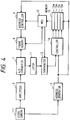
- Fig. 4 is a block diagram of a portion associated with detection of the positions of bright points (bright point position detection unit) of the ophthalmologic apparatus according to the first embodiment of the present invention.
- the bright point position detection unit comprises a video camera 111 as the image pickup unit, an amplifier 6, an A/D converter 7, a frame memory 8, an address controller 9, an MPU (microprocessor unit) 10, a latch 11, a magnitude comparator 12, an address generator 13, an area memory controller 14, and an area memory 15.
- the video camera 111 has a plurality of pixels.
- the image of the eye 101 to be examined is picked up by the video camera 111.
- the picked-up image signals of the eye 101 to be examined are scanned in turn from the upper left pixel to the lower right pixel of the video camera 111, and are output to the amplifier 6.
- a synchronization signal from the video camera 111 is output to the address generator 13.
- This synchronization signal is a signal representing the pixel of the video camera 111 from which the image signal is being read.
- the image signals input to the amplifier 6 are amplified or attenuated, and are then input to the A/D converter 7.
- Image data which are sequentially converted into digital data by the A/D converter 7 are input to and stored (memorized) in the frame memory 8.
- the address generator 13 generates a frame memory address corresponding to the synchronization signal of the pixel which outputs the image signal to the amplifier 6.
- the frame memory address is output to the address controller 9 and the area memory 15.
- the frame memory addresses of required image data are input from the address controller 9 to the frame memory 8.
- the MPU 10 memorizes image data in the frame memory 8
- the MPU 10 inputs the destination frame memory addresses to the frame memory 8.
- the digital image data converted by the A/D converter 7 are held in the data latch 11, and are then input to the magnitude comparator 12.
- the image data are compared with a threshold set in advance in the MPU 10. As a result of comparison, if image data is larger than the threshold, the area memory controller 14 memorizes the frame memory address at that time in the area memory 15.
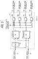
- Fig. 5 shows a circuit of the area memory controller 14 associated with write control to the area memory 15.
- the frame memory address generated by the address generator 13 is output to the area memory controller 14 via a frame memory address X coordinate signal line 31 and a frame memory address Y coordinate signal line 32.
- the area memory controller 14 comprises an inverter 18, magnitude comparators 16 and 17, and AND gates 19a, 19b, 19c, and 19d.
- the frame memory address X coordinate signal line 31 is connected to the inverter 18 and the magnitude comparator 17, and the frame memory address Y coordinate signal line 32 is connected to the magnitude comparators 16 and 17.
- the comparator 16 is connected to the AND gates 19a, 19b, 19c, and 19d, and the comparator 17 is also connected to the AND gates 19a, 19b, 19c, and 19d.
- the comparator 12 is also connected to the AND gates 19a, 19b, 19c, and 19d.
- each of the X coordinate address output from the frame memory address X coordinate signal line 31, and the Y coordinate address output from the address Y coordinate signal line 32 is set to be 9-bit data so as to assume a value ranging from 0 to 51.
- an x ⁇ value is (511 - x).
- the comparator 16 receives the x ⁇ value obtained by inverting the X coordinate address, and a y value as the Y coordinate address.
- the comparator 17 receives the x value of the X coordinate address, and the y value of the Y coordinate address.
- the comparator 16 when the y value is larger than the x ⁇ value, the comparator 16 outputs an H-level signal (1); otherwise, i.e., when the y value is smaller than the x ⁇ value, the comparator 16 outputs an L-level signal (0).
- the comparator 17 When the y value is larger than the x value, the comparator 17 outputs an H-level signal (1); otherwise, it outputs an L-level signal (0).
- a region above or below the straight lines 30 and 40 (Fig. 3) can be expressed by the outputs from the comparators 16 and 17, and can be classified into the regions 1 to 4.
- the frame memory address in the region 1 is memorized in the partial memory 15a; the frame memory address in the region 2 is memorized in the partial memory 15b; the frame memory address in the region 3 is memorized in the partial memory 15c; and the frame memory address in the region 4 is memorized in the partial memory 15d.
- the frame memory address output from the address generator 13 is memorized in one of the partial memories 15a, 15b, 15c, and 15d in correspondence with the writing signals 14a, 14b, 14c, and 14d.
- the partial memories 15a, 15b, 15c, and 15d are memories each for memorizing one frame memory address. A new frame memory address is overwritten on the previously memorized frame memory address.
- the frame memory addresses of the pixels finally scanned in the corresponding regions of the pixels exceeding the threshold in the corresponding regions are respectively memorized in the partial memories 15a to 15d.
- the advantage of allowing the MPU 10 to make read/write accesses of the frame memory 8 is that the MPU 10 can confirm if accurate frame memory addresses are memorized in the area memory 15.
- the MPU 10 reads out the frame memory addresses memorized in the partial memories 15a to 15d, and calculates the centroids of the bright points of the corresponding regions on the basis of the readout frame memory addresses.
- Fig. 6 shows the positional relationship between the bright points memorized in the frame memory 8 and the regions, an enlarged plan view of one bright point, and the light intensity distribution along a line crossing the center of the bright point.
- arrows illustrated on the enlarged view of the bright point 4 represent scanning lines.
- the intensity of the luminance is highest at a center 43 of the bright point 4
- the threshold is equal to the intensity of the luminance at a point 42
- the intensity of the luminance exceeds the noise level at a point 41.
- the frame memory address of the point 1 (of a pixel included therein) in the bright point 4, which point 1 is the first scanned point which exceeds the threshold is stored in the area memory 15d.
- the centroid of the bright point 4 can be calculated by determining the recognition area of the bright point 4 from, e.g., the radiation magnification of the measurement light sources 102a and 102b.
- the square can always include the entire bright point.
- a square including the bright point is calculated on the basis of the frame memory address which is stored in the area memory 15 and exceeds the threshold first, and the centroid of the bright point can be calculated for all pixels in the square in consideration of the noise level.
- 2Rmax may be assured from the coordinates (x0, y0) in the obliquely right downward direction (toward a coordinate point B in Fig. 7), and only Rmax may be assured in a direction of a coordinate point A.
- the image data corresponding to the square are read from the frame memory 8, and the centroid of the bright point is calculated based on the read image data.
- the region shown in Fig. 8 includes 16 pixels, and addresses (X coordinate, Y coordinate) of these pixels are (1, 1), (1, 2), (1, 3), (1, 4), (2, 1), (2, 2),..., (1, 4), (2, 4), (3, 4), and (4, 4), and luminance data of these pixels are respectively 0, 1, 1, 0, 1, 2, 2, 1, 1, 2, 2, 1, 0, 1, 1, and 0 in turn.
- the noise level is defined to be 1.
- the address of a pixel whose luminance is equal to or higher than the noise level is represented by (Xi, Yj) (for each of i and j is one of 1, 2, 3, and 4), and the luminance at the address (Xi, Yj) is represented by Pij.
- the centroid of this rectangular region is represented by (X0, Y0)
- X0 and Y0 are calculated as follows. More specifically, the centroid is (2.5, 2.5).
- memories 15a to 15d may store only the addresses at which the value of data exceeds the threshold finally in each region.
- Fig. 9 is a block diagram of a portion associated with detection of the positions of bright points (bright point position detection unit) of the ophthalmologic apparatus according to the second embodiment of the present invention.
- a frame memory 58 comprises an image data memory section 58a and a region memory section 58b, and an area memory controller 54 writes addresses in the memories 15a to 15d corresponding to regions designated by the region memory section 58b.
- Fig. 10 shows a circuit of the area memory controller 54 associated with write control to the memory 15, and the memory formats of the image data memory section 58a and the region memory section 58b of the frame memory 58.
- the frame memory 58 stores pixel data (luminance information) of pixels and region information (information indicating the regions 1 to 4). As shown in Fig. 10, the frame memory 58 stores one address as 16-bit data.
- the lower 8 bits (bits 0 to 7) of the 16-bit data store image data as the image data memory section 58a, and the upper 8 bits (bits 8 to 15) store region information as the region memory section 58b.
- bits 12 to 15 are undefined bits to provide versatility.
- Information indicating the region where the corresponding pixel is present is written in advance in the region memory section 58b, and the information indicating the region is read by the controller 54 while storing image data.
- Which partial memory of the area memory 15 memorizes the frame memory address output from the address generator 13 is determined based on the bit indicating the area, which bit is read out from the controller 54.
- a circuit for determining the region to which a pixel belongs can be omitted unlike in the first embodiment. Also, a region having a complicated shape can be set. Furthermore, the shape of the region can be easily changed;
- the centroids of the four bright points are calculated.
- the present invention can be applied to detection of a larger number of bright points, as a matter of course.
- the present invention can be applied to a case wherein a ring image is projected onto the cornea or the fundus of the eye in place of bright points, and an equation of ellipse is obtained from the projected image.
- the coordinates of five points on an ellipse need only be obtained. Therefore, as shown in Fig. 11, five regions are set for an ellipse 23, and the address at which the luminance exceeds the threshold can be detected for each region.
- a light source having a pattern (circular pattern) formed with a circular light-shielding portion is used as the illumination means 102, and the circular pattern is projected onto the eye to be examined.
- a circular pattern image reflected by the eye to be examined is an ellipse 23, as shown in Fig. 11.
- the curvature of the cornea is then calculated based on the circular pattern and the ellipse 23.
- the width of the region is smaller, the number of points crossing the ellipse 23 becomes smaller, and the calculation processing speed can be increased.
- each region is defined by a line segment.
- the addresses of pixels of the ellipse 23, which pixels cross the regions, are obtained, and when the equation of ellipse is obtained based on the addresses of these pixels, the curvature of the eye to be examined can be calculated.
- the regions need not always be set at equal angular intervals.
- the frame memory 8 is not always needed in the present invention. Even when the frame memory 8 is omitted, image data exceeding the threshold, and the addresses of the image data can be detected.
- the frame memory 8 when the frame memory 8 is arranged, it can be confirmed if the image data exceeding the threshold, and the addresses of the image data coincide with each other, and the measured values of the eye to be examined can be calculated while displaying an image on a TV screen.
- an observation optical system may be added to the ophthalmologic apparatus.
Landscapes
- Engineering & Computer Science (AREA)
- Health & Medical Sciences (AREA)
- Life Sciences & Earth Sciences (AREA)
- Physics & Mathematics (AREA)
- Surgery (AREA)
- Animal Behavior & Ethology (AREA)
- Biomedical Technology (AREA)
- Heart & Thoracic Surgery (AREA)
- Medical Informatics (AREA)
- Molecular Biology (AREA)
- Biophysics (AREA)
- Ophthalmology & Optometry (AREA)
- General Health & Medical Sciences (AREA)
- Public Health (AREA)
- Veterinary Medicine (AREA)
- Geometry (AREA)
- Computer Vision & Pattern Recognition (AREA)
- General Physics & Mathematics (AREA)
- Theoretical Computer Science (AREA)
- Eye Examination Apparatus (AREA)
Applications Claiming Priority (2)
| Application Number | Priority Date | Filing Date | Title |
|---|---|---|---|
| JP29620792A JP3298185B2 (ja) | 1992-11-05 | 1992-11-05 | 眼科装置 |
| JP296207/92 | 1992-11-05 |
Publications (2)
| Publication Number | Publication Date |
|---|---|
| EP0596749A1 true EP0596749A1 (fr) | 1994-05-11 |
| EP0596749B1 EP0596749B1 (fr) | 1999-05-26 |
Family
ID=17830562
Family Applications (1)
| Application Number | Title | Priority Date | Filing Date |
|---|---|---|---|
| EP93308866A Expired - Lifetime EP0596749B1 (fr) | 1992-11-05 | 1993-11-05 | Appareil ophtalmologique |
Country Status (4)
| Country | Link |
|---|---|
| US (1) | US5548355A (fr) |
| EP (1) | EP0596749B1 (fr) |
| JP (1) | JP3298185B2 (fr) |
| DE (1) | DE69325074T2 (fr) |
Cited By (6)
| Publication number | Priority date | Publication date | Assignee | Title |
|---|---|---|---|---|
| EP0687441A1 (fr) * | 1994-06-17 | 1995-12-20 | Canon Kabushiki Kaisha | Dispositif électronique comportant un appareil détecteur point d'image |
| WO1996000031A1 (fr) * | 1994-06-27 | 1996-01-04 | Cain Research Pty. Ltd. | Dispositif et procede d'evaluation de la refraction de l'×il |
| DE19731303A1 (de) * | 1997-07-13 | 1999-02-04 | Smi Senso Motoric Instr Gmbh | Verfahren und Vorrichtung zum kontaktlosen, helmfreien Messen der Blickrichtung von Augen bei größeren und schnelleren Kopf- und Augenbewegungen |
| EP0958784A1 (fr) * | 1998-05-18 | 1999-11-24 | Masao Ito | Appareil de mesure de l'épaisseur de l'intima-media et système de diagnostique de l'artériosclérose |
| DE19731301C2 (de) * | 1997-07-13 | 2001-05-10 | Smi Senso Motoric Instr Gmbh | Vorrichtung zum Steuern eines Mikroskopes mittels Blickrichtungsanalyse |
| WO2004049258A1 (fr) * | 2002-11-25 | 2004-06-10 | Sensovation Ag | Procede pour saisir une propriete d'au moins un objet |
Families Citing this family (17)
| Publication number | Priority date | Publication date | Assignee | Title |
|---|---|---|---|---|
| JP3448795B2 (ja) * | 1996-04-11 | 2003-09-22 | 株式会社ニコン | 眼科装置 |
| US5735283A (en) * | 1996-10-09 | 1998-04-07 | Snook; Richard Kieth | Surgical keratometer system for measuring surface topography of a cornea during surgery |
| US6215891B1 (en) | 1997-03-26 | 2001-04-10 | Oki Electric Industry Co., Ltd. | Eye image recognition method eye image selection method and system therefor |
| JP4545871B2 (ja) * | 2000-03-27 | 2010-09-15 | キヤノン株式会社 | 眼科装置 |
| JP4210995B2 (ja) * | 2003-09-19 | 2009-01-21 | ノーリツ鋼機株式会社 | 輝点検出方法及び輝点検出プログラム |
| JP4426839B2 (ja) * | 2003-12-26 | 2010-03-03 | 株式会社ニデック | 眼底撮影装置 |
| EP1825804A1 (fr) * | 2004-10-27 | 2007-08-29 | Kowa Company Ltd. | Appareil de mesure ophtalmologique |
| US7995137B2 (en) * | 2006-05-01 | 2011-08-09 | Himax Technologies, Limited | Exposure compensation method for digital image |
| WO2008101359A1 (fr) * | 2007-02-23 | 2008-08-28 | Mimo Ag | Appareil ophtalmologique pour imagerie d'un œil par tomographie à cohérence optique |
| US9168173B2 (en) | 2008-04-04 | 2015-10-27 | Truevision Systems, Inc. | Apparatus and methods for performing enhanced visually directed procedures under low ambient light conditions |
| US10117721B2 (en) | 2008-10-10 | 2018-11-06 | Truevision Systems, Inc. | Real-time surgical reference guides and methods for surgical applications |
| US9226798B2 (en) | 2008-10-10 | 2016-01-05 | Truevision Systems, Inc. | Real-time surgical reference indicium apparatus and methods for surgical applications |
| US9173717B2 (en) * | 2009-02-20 | 2015-11-03 | Truevision Systems, Inc. | Real-time surgical reference indicium apparatus and methods for intraocular lens implantation |
| WO2014036499A1 (fr) | 2012-08-30 | 2014-03-06 | Truevision Systems, Inc. | Système d'imagerie et procédés affichant une image reconstituée multidimensionnelle et fusionnée |
| US10917543B2 (en) | 2017-04-24 | 2021-02-09 | Alcon Inc. | Stereoscopic visualization camera and integrated robotics platform |
| US10299880B2 (en) | 2017-04-24 | 2019-05-28 | Truevision Systems, Inc. | Stereoscopic visualization camera and platform |
| US11083537B2 (en) | 2017-04-24 | 2021-08-10 | Alcon Inc. | Stereoscopic camera with fluorescence visualization |
Citations (4)
| Publication number | Priority date | Publication date | Assignee | Title |
|---|---|---|---|---|
| US4678297A (en) * | 1982-11-30 | 1987-07-07 | Canon Kabushiki Kaisha | Ophthalmic instrument |
| EP0317768A1 (fr) * | 1987-11-25 | 1989-05-31 | Taunton Technologies, Inc. | Appareil pour des mesures de topographie |
| US4859051A (en) * | 1986-12-25 | 1989-08-22 | Tokyo Kogaku Kikai Kabushiki Kaisha | Eye testing apparatus |
| US5110200A (en) * | 1989-06-30 | 1992-05-05 | Technitex, Inc. | Video keratometer |
Family Cites Families (5)
| Publication number | Priority date | Publication date | Assignee | Title |
|---|---|---|---|---|
| US4878750A (en) * | 1985-01-25 | 1989-11-07 | Canon Kabushiki Kaisha | Ophthalmic measuring apparatus |
| JPS62290435A (ja) * | 1986-06-09 | 1987-12-17 | キヤノン株式会社 | 角膜形状測定装置 |
| JPH0753152B2 (ja) * | 1986-08-18 | 1995-06-07 | 株式会社トプコン | 画像計測処理装置のメモリデ−タ走査方式 |
| JP3042851B2 (ja) * | 1990-01-29 | 2000-05-22 | 株式会社ニデック | 角膜形状測定装置 |
| US5214456A (en) * | 1991-10-09 | 1993-05-25 | Computed Anatomy Incorporated | Mapping of corneal topography with display of pupil perimeter |
-
1992
- 1992-11-05 JP JP29620792A patent/JP3298185B2/ja not_active Expired - Lifetime
-
1993
- 1993-11-01 US US08/144,248 patent/US5548355A/en not_active Expired - Lifetime
- 1993-11-05 DE DE69325074T patent/DE69325074T2/de not_active Expired - Lifetime
- 1993-11-05 EP EP93308866A patent/EP0596749B1/fr not_active Expired - Lifetime
Patent Citations (4)
| Publication number | Priority date | Publication date | Assignee | Title |
|---|---|---|---|---|
| US4678297A (en) * | 1982-11-30 | 1987-07-07 | Canon Kabushiki Kaisha | Ophthalmic instrument |
| US4859051A (en) * | 1986-12-25 | 1989-08-22 | Tokyo Kogaku Kikai Kabushiki Kaisha | Eye testing apparatus |
| EP0317768A1 (fr) * | 1987-11-25 | 1989-05-31 | Taunton Technologies, Inc. | Appareil pour des mesures de topographie |
| US5110200A (en) * | 1989-06-30 | 1992-05-05 | Technitex, Inc. | Video keratometer |
Cited By (11)
| Publication number | Priority date | Publication date | Assignee | Title |
|---|---|---|---|---|
| US5576780A (en) * | 1992-05-26 | 1996-11-19 | Cain Research Pty. Ltd. | Method for evaluation of length of focus of the eye |
| US5684561A (en) * | 1992-05-26 | 1997-11-04 | Daphne Eye Technologies | Device and method for evaluation of refraction of the eye |
| EP0687441A1 (fr) * | 1994-06-17 | 1995-12-20 | Canon Kabushiki Kaisha | Dispositif électronique comportant un appareil détecteur point d'image |
| US5757428A (en) * | 1994-06-17 | 1998-05-26 | Canon Kabushiki Kaisha | Electronic equipment having viewpoint detection apparatus with determination of abnormal operation of eyeball illumination unit |
| CN1132554C (zh) * | 1994-06-17 | 2003-12-31 | 佳能株式会社 | 具有视点检测功能的电子设备 |
| WO1996000031A1 (fr) * | 1994-06-27 | 1996-01-04 | Cain Research Pty. Ltd. | Dispositif et procede d'evaluation de la refraction de l'×il |
| DE19731303A1 (de) * | 1997-07-13 | 1999-02-04 | Smi Senso Motoric Instr Gmbh | Verfahren und Vorrichtung zum kontaktlosen, helmfreien Messen der Blickrichtung von Augen bei größeren und schnelleren Kopf- und Augenbewegungen |
| DE19731301C2 (de) * | 1997-07-13 | 2001-05-10 | Smi Senso Motoric Instr Gmbh | Vorrichtung zum Steuern eines Mikroskopes mittels Blickrichtungsanalyse |
| DE19731303B4 (de) * | 1997-07-13 | 2009-02-26 | Smi Senso Motoric Instruments Gmbh | Verfahren und Vorrichtung zum kontaktlosen, helmfreien Messen der Blickrichtung von Augen bei Kopf- und Augenbewegungen |
| EP0958784A1 (fr) * | 1998-05-18 | 1999-11-24 | Masao Ito | Appareil de mesure de l'épaisseur de l'intima-media et système de diagnostique de l'artériosclérose |
| WO2004049258A1 (fr) * | 2002-11-25 | 2004-06-10 | Sensovation Ag | Procede pour saisir une propriete d'au moins un objet |
Also Published As
| Publication number | Publication date |
|---|---|
| EP0596749B1 (fr) | 1999-05-26 |
| JP3298185B2 (ja) | 2002-07-02 |
| US5548355A (en) | 1996-08-20 |
| DE69325074D1 (de) | 1999-07-01 |
| JPH06142045A (ja) | 1994-05-24 |
| DE69325074T2 (de) | 1999-12-16 |
Similar Documents
| Publication | Publication Date | Title |
|---|---|---|
| US5548355A (en) | Ophthalmologic apparatus detecting position of bright points on an eye to be examined | |
| US4523821A (en) | Device for examining anterior sections of the eye | |
| US5325133A (en) | Device for measuring a retina reflected light amount and a gaze detecting apparatus using the same | |
| US5280312A (en) | Visual axis detection apparatus | |
| JP3873401B2 (ja) | 3次元計測システム | |
| US5225862A (en) | Visual axis detector using plural reflected image of a light source | |
| US6331887B1 (en) | Outdoor range finder | |
| NO753655L (fr) | ||
| EP0392744A1 (fr) | Méthode de mesure ophtalmologique et appareil | |
| US5815240A (en) | Ophthalmologic device having means for classifying the picture data in the frame memory into the bright point regions and the mask regions | |
| US5168322A (en) | Surface inspection using retro-reflective light field | |
| CN111044261B (zh) | 眼底相机照明均匀性检测方法、装置、存储介质和系统 | |
| EP0183565A1 (fr) | Procédé et appareil pour comparer des objets à un modèle | |
| US5864382A (en) | Opthalmic apparatus for analyzing a section of an anterior part of an eye | |
| EP1057446A2 (fr) | Appareil de mesure de la forme de la cornée | |
| JP2001509627A (ja) | 人物の少なくとも1つの特徴領域の位置を検出し、この位置に依存する機器に対する制御信号を発生するための装置を動作するための方法 | |
| US5260557A (en) | Method and apparatus for acquisition and tracking of light sources in a transient event rich environment | |
| JPH05272970A (ja) | 自動レベル | |
| JPH09257422A (ja) | エッジ検出方式 | |
| JPH0323856B2 (fr) | ||
| US4806746A (en) | Apparatus and process for focussing of an optical display system | |
| JP3214117B2 (ja) | 交換レンズ及び焦点検出可能なカメラ | |
| JPH0949706A (ja) | レーザ光を用いた被計測物の前後方向の移動量測定方法 | |
| JP2001017411A (ja) | 画像処理装置 | |
| US5694198A (en) | Apparatus including waveform rectifying means and method for eye examination |
Legal Events
| Date | Code | Title | Description |
|---|---|---|---|
| PUAI | Public reference made under article 153(3) epc to a published international application that has entered the european phase |
Free format text: ORIGINAL CODE: 0009012 |
|
| AK | Designated contracting states |
Kind code of ref document: A1 Designated state(s): DE FR GB |
|
| 17P | Request for examination filed |
Effective date: 19941025 |
|
| 17Q | First examination report despatched |
Effective date: 19960213 |
|
| GRAG | Despatch of communication of intention to grant |
Free format text: ORIGINAL CODE: EPIDOS AGRA |
|
| GRAG | Despatch of communication of intention to grant |
Free format text: ORIGINAL CODE: EPIDOS AGRA |
|
| GRAH | Despatch of communication of intention to grant a patent |
Free format text: ORIGINAL CODE: EPIDOS IGRA |
|
| GRAH | Despatch of communication of intention to grant a patent |
Free format text: ORIGINAL CODE: EPIDOS IGRA |
|
| GRAA | (expected) grant |
Free format text: ORIGINAL CODE: 0009210 |
|
| AK | Designated contracting states |
Kind code of ref document: B1 Designated state(s): DE FR GB |
|
| REF | Corresponds to: |
Ref document number: 69325074 Country of ref document: DE Date of ref document: 19990701 |
|
| ET | Fr: translation filed | ||
| PLBE | No opposition filed within time limit |
Free format text: ORIGINAL CODE: 0009261 |
|
| 26N | No opposition filed | ||
| REG | Reference to a national code |
Ref country code: GB Ref legal event code: IF02 |
|
| PGFP | Annual fee paid to national office [announced via postgrant information from national office to epo] |
Ref country code: DE Payment date: 20121031 Year of fee payment: 20 Ref country code: FR Payment date: 20121130 Year of fee payment: 20 |
|
| PGFP | Annual fee paid to national office [announced via postgrant information from national office to epo] |
Ref country code: GB Payment date: 20121031 Year of fee payment: 20 |
|
| REG | Reference to a national code |
Ref country code: DE Ref legal event code: R071 Ref document number: 69325074 Country of ref document: DE |
|
| REG | Reference to a national code |
Ref country code: GB Ref legal event code: PE20 Expiry date: 20131104 |
|
| PG25 | Lapsed in a contracting state [announced via postgrant information from national office to epo] |
Ref country code: DE Free format text: LAPSE BECAUSE OF EXPIRATION OF PROTECTION Effective date: 20131106 Ref country code: GB Free format text: LAPSE BECAUSE OF EXPIRATION OF PROTECTION Effective date: 20131104 |