EP0596751B1 - Messvorrichtung für Blechbiegewinkel - Google Patents
Messvorrichtung für Blechbiegewinkel Download PDFInfo
- Publication number
- EP0596751B1 EP0596751B1 EP93308871A EP93308871A EP0596751B1 EP 0596751 B1 EP0596751 B1 EP 0596751B1 EP 93308871 A EP93308871 A EP 93308871A EP 93308871 A EP93308871 A EP 93308871A EP 0596751 B1 EP0596751 B1 EP 0596751B1
- Authority
- EP
- European Patent Office
- Prior art keywords
- sheet material
- links
- angle
- bending angle
- bending
- Prior art date
- Legal status (The legal status is an assumption and is not a legal conclusion. Google has not performed a legal analysis and makes no representation as to the accuracy of the status listed.)
- Expired - Lifetime
Links
Images


Classifications
-
- B—PERFORMING OPERATIONS; TRANSPORTING
- B21—MECHANICAL METAL-WORKING WITHOUT ESSENTIALLY REMOVING MATERIAL; PUNCHING METAL
- B21D—WORKING OR PROCESSING OF SHEET METAL OR METAL TUBES, RODS OR PROFILES WITHOUT ESSENTIALLY REMOVING MATERIAL; PUNCHING METAL
- B21D5/00—Bending sheet metal along straight lines, e.g. to form simple curves
- B21D5/02—Bending sheet metal along straight lines, e.g. to form simple curves on press brakes without making use of clamping means
- B21D5/0209—Tools therefor
-
- B—PERFORMING OPERATIONS; TRANSPORTING
- B21—MECHANICAL METAL-WORKING WITHOUT ESSENTIALLY REMOVING MATERIAL; PUNCHING METAL
- B21D—WORKING OR PROCESSING OF SHEET METAL OR METAL TUBES, RODS OR PROFILES WITHOUT ESSENTIALLY REMOVING MATERIAL; PUNCHING METAL
- B21D5/00—Bending sheet metal along straight lines, e.g. to form simple curves
- B21D5/02—Bending sheet metal along straight lines, e.g. to form simple curves on press brakes without making use of clamping means
-
- G—PHYSICS
- G01—MEASURING; TESTING
- G01B—MEASURING LENGTH, THICKNESS OR SIMILAR LINEAR DIMENSIONS; MEASURING ANGLES; MEASURING AREAS; MEASURING IRREGULARITIES OF SURFACES OR CONTOURS
- G01B5/00—Measuring arrangements characterised by the use of mechanical techniques
- G01B5/24—Measuring arrangements characterised by the use of mechanical techniques for measuring angles or tapers; for testing the alignment of axes
Definitions
- This invention relates to a sheet material bending angle detector and to an operation method of a press machine using the bending angle detector.
- JP-A-60-247415 a proposal has been made (JP-A-60-247415) wherein a sensor for measuring the distance to an outer surface of the bent sheet or to a point below an apex is disposed in the lower die, and a bending angle is computed from this distance.
- DE-B-2044199 which is considered to be the nearest prior art discloses a similar arrangement having both mechanical and photoelectric measurement sensors. Since dedicated sensors must be provided individually to different lower dies, these arrangements are expensive and moreover, since measurement is indirect measuring accuracy is not very high.
- JP-A-57-202928 Another proposal has been made (JP-A-57-202928) wherein a gauge is disposed by the side of the lower die, and a bending angle is computed from a horizontal distance and a vertical distance from groove edges at a specific point of the portion of the sheet material protruding diagonally upwards from a groove and forming one of the sides of the angle.
- the thickness of the sheet material is not constant or in other words, if the inner and outer surfaces of the sheet material are not precisely parallel and moreover, if the attitude of the sheet material inside the groove changes, measurement can no longer be made accurately. Furthermore, measurement cannot be made at all for those sheet materials which do not protrude from the groove up to the gauge.
- the present invention seeks to provide a bending angle detector which is relatively simple in construction, and can directly measure a bending angle of a bent sheet material irrespective of its attitude. Measurement and re-bending can be repeated automatically until a desired bending angle is obtained, by the use of this bending angle detector.
- a bending angle detector for a sheet material comprising:
- a bending angle detector for a sheet material comprising the features of claim 2.
- an operation method comprising the combination of features according to claim 3.
- the bending angle is measured by bringing the first and second links of the bending angle detector into contact with the inner surfaces of both sides of the sheet material defining the angle between them. Therefore, measurement can be made without being affected by the attitude of the sheet material and by the change of the thickness of the sheet material, and moreover, without being affected by the dimension of the sides of the sheet material defining the angle between them. Moreover, this measurement can be carried out under the state where the load applied to the sheet material is removed completely, and hence, without any influences of spring-back.
- the bending operation is first carried out at an angle corresponding to insufficient bending of the sheet material, and measurement of the bending angle, the correction of the stroke of the movable die or the groove depth, and the bending operation, are automatically repeated for the sheet material in the press machine. In this way, it is possible to rapidly achieve a precise bending angle.
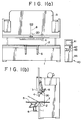
- Fig. 1 depicts a press brake equipped with a bending angle detector for a sheet material according to the present invention.
- a lower die 2 consisting of a plurality of split die portions each having a rectangular groove of a variable depth is mounted onto a bed 1.
- a ram 3 is allowed to move up and down relative to this bed 1, and an upper die 4 is fixed to the lower end of this ram 3.
- a sheet material 5 to be bent is placed on a link mechanism support device 6 positioned on the front side of the lower die 2, is supported on the support device 6 by suitable means, whenever necessary, and is pushed until it strikes a gauge 7 which is at the back of the lower die 2 and decides the dimension of one of the sides of a bending angle.
- the ram 3 is lowered, and the upper die 4 pushes the sheet material 5 into the rectangular groove of the lower die 2 and bends it.
- the front side of the sheet material 5 is lifted up from the support device 6 as indicated by two-dot-chain line.
- the upper die 4 is again moved up and returned by the ram 3, and a bending angle detector is then fitted into the angle formed within the bend of the sheet material 5 by a feed mechanism 8 fitted to the ram 3.
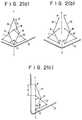
- a fixed node O at the lower end of a 4-node link mechanism consisting of four links 11, 12, 13 and 14 pivotally connected to one another at nodes O, P, Q and R is positioned inside the apex of an angle described by the bent sheet material 5 (whereby the node O is shown a little spaced apart from the apex for ease of understanding), and that the opposed node P is movable on a Y - Y axis which is a bisector of this angle.
- the upper and lower nodes P and O of the link can be divided into two nodes P', P'' and O', O'' which are symmetrical with respect to the Y - Y axis.
- a 3-node link mechanism having only two links 12 and 14 positioned on one of the sides of the Y - Y axis.
- the nodes O and P existing at the other end of each of the two links 12 and 14 pivotally connected to each other through the node R exist on the Y - Y axis parallel to one of the sides of the angle defined by the bent sheet material 5, that the node O is fixed and positioned inside the apex of the angle defined by the sheet material 5 (the node O being shown at a position spaced apart a little from the apex for ease of understanding), and that the node P is movable on the Y - Y axis.
- the angle a defined between the link 12 and the Y - Y axis is equal to the bending angle of the sheet material 5.
- the displacement S of the node P from the initial position is related with the change of the angle ⁇ . Therefore, the bending angle of the sheet material 5 can be determined from the angle ⁇ by measuring this displacement S.
- Fig. 3 shows a practical construction of the bending angle detector 20 corresponding to Fig. 2(b).
- the links 11 and 12 of the link mechanism are pivotally connected to a horizontal arm 21a of a detector main body 21 by pins functioning as the fixed nodes O', O'' at the lower end.
- the upper end each of the links 13 and 14, which are pivotally connected to these links 11 and 12 by pins as the nodes Q and R, is fitted to a slider 22 by pins as the nodes P' and P''.
- This slider 22 is so guided by a guide plate 21b fixed to the detector main body 21 as to be capable of linearly moving up and down.
- a rack 23 is fitted to the side of this slider 22, and a pinion 24 engaging with the rack 23 is transmission-coupled with a rotary encoder 27 through gears 25 and 26 meshing with the pinion 24.
- the links 11, 12 and 13, 14 can be fixed to the horizontal arm 21a and to the slider 22 by using one each of the pins O and P in place of the two pins O', O'' and P', P'', as in Fig. 2(a).
- the detector main body 21 is supported by a fitting member 30 through attitude regulation devices 28 and 29 so that the links 11 and 12 can come into reliable contact with the sheet surfaces in conformity with the attitude of the sheet material 5.
- the attitude regulation device 28 comprises a belt plate 28b accommodated in a vertical groove 28a at the lower end of the main body 21 and having a width a little smaller than the groove width, a pin 28c loosely fitting to the fitting member 30 and supporting the belt plate 28b so as to support the belt plate 28b swingable a bit inside the groove 28a, and a pin 28d fitting loosely to the belt plate 28b and embedded in the main body 21.
- the attitude regulation device 29 comprises a pin 29b so fixed to the main body 21 as to penetrate through the fitting member 30 with a ring-like gap 29a therebetween.
- the sheet material 5 is bent inside the rectangular groove of the lower die 2 as is well known in the art, and the upper die 4 is again moved up.
- the detector 20 is inserted (Fig. 4) into the angle within the bending range of the sheet material 5 through the support mechanism 8 (Fig. 1), and is stopped at a predetermined position.
- the slider 22 is pushed down by a spring 31 until the links 11 and 12 come into reliable contact with the surfaces of the sheet material 5 defining the angle between them.
- Displacement of the nodes P' and P'' and hence, the displacement of the slider 22, is amplified by the rack 23, the pinion 24 and the gears 25 and 26, is converted to a rotating quantity by them, and is thereafter converted to electric signals such as pulses by the rotary encoder 27.
- the detector 20 shown in Fig. 5 is suitable for detecting the bending angle of the sheet material 5 to be bent into an L shape, and this detector corresponds to Fig. 2(c).
- the linear displacement of the slider 22 is converted to electrical signals by a linear encoder 27 or by a differential transformer.
- the differential transformer When the differential transformer, is employed, its analog output signal is converted to a pulse signal by A/D conversion.
- a control panel 40 is disposed by the side of the press brake, and includes a display 41, a data processor 42, a data input device 43 and a controller 44.
- Bending of the sheet material 5 is carried out in accordance with the principle of 3-point bending, as described, for example, in JP-U-62-13696.
- the bending angle of the sheet material is determined by the gap between both groove edges of the rectangular groove 2a of the lower die 2 and by the groove depth, provided that no spring-back exists.
- the depth of the rectangular groove 2a can be adjusted by a plurality of pan head pins 2b which are movably guided inside a plurality of vertical holes communicating with the rectangular groove 2a and which define the groove bottom.
- the bending angle of the sheet material is calculated and stored (45) inside the data processor 42 from the signal of the encoder 27 of the bending angle detector, and is compared (47) with a target value (46), and the groove depth of the lower die and hence, the height of the pan head pins 2b, is adjusted by the controller 44 in accordance with the difference obtained by the comparison.
- Fig. 7 shows the data processor 42.
- the output signal of the encoder 27 of the bending angle detector is counted by a counter 51, is processed by a CPU 53, an ROM 54 and an RAM 55 connected to one another by a data bus 52, and is supplied to the controller 44 and to the display 41 through interfaces 56 and 57, respectively.
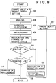
- Step 105 the groove depth of the lower die 2 corresponding to a bending angle 90° + 1° is first set in consideration of over-bending.
- the sheet material 5 is bent by lowering the upper die 4 by the ram 3 (Step 106). While the sheet material 5 is kept held on the support mechanism 6, the upper mold 4 is moved up.
- the detector 20 is inserted by the feed mechanism 8 into the range of the angle of the bent sheet material 5, that is, the product, to be measured (Step 107) and the bending angle is measured.
- the displacement of the node P or P' and P'' of the link mechanism is transferred to the data processor 42 (Step 108).
- the bending angle is computed, is supplied to the controller 44 and is thereafter stored in the memory (Step 109). In the mean time, the detector 20 is removed by the feed mechanism 8 from the product.
- the bending operation is completed if the measured bending angle (actual value) is within the positive allowable limit of the difference from the target value 90°, such as 30' (Step 110) and furthermore, if it is within a negative allowable limit such as -30' (Step 111).
- a product having the desired bending angle can be obtained by bending the sheet material with the groove depth of the lower die 2 at that time.
- a correction value of the groove depth is calculated (Step 112).
- the correction value is set to the controller 44 and the groove depth is automatically set on the basis of this correction value (Step 105').
- the procedures 106 to 111 are repeated until the desired bending angle can be obtained.
- Step 114 If the measured bending angle does not fall within the negative allowable limit of the error from the target value, this means over-bending. Accordingly, measurement is stopped (Step 114), and the sheet material is withdrawn.
Landscapes
- Engineering & Computer Science (AREA)
- Mechanical Engineering (AREA)
- Physics & Mathematics (AREA)
- General Physics & Mathematics (AREA)
- Bending Of Plates, Rods, And Pipes (AREA)
- Investigating Strength Of Materials By Application Of Mechanical Stress (AREA)
- Length Measuring Devices With Unspecified Measuring Means (AREA)
Claims (3)
- Blechbiegewinkeldetektor, enthaltend:erste und zweite Hebel (11, 12), von denen jeder achssymmetrisch im Bezug auf den anderen angeordnet ist; unddritte und vierte Hebel (13, 14), von denen jeder in ähnlicher Achssymmetrie mit Bezug zur gleichen Symmetrieachse angeordnet ist und jeder Hebel an einem Ende schwenkbar mit einem Ende eines entsprechenden Hebels der ersten und zweiten Hebel (11, 12) verbunden ist, dadurch gekennzeichnet, daß:jeder der ersten und zweiten Hebel schwenkbar an einem Ende mit einem Detektorhauptgehäuse (21) verbunden ist;das andere Ende des dritten und vierten Hebels (13, 14) vom Detektorhauptgehäuse (21) derart gehalten wird, daß sie sich entlang der Symmetrieachse oder entlang paralleler Linien bewegen können, die sich auf beiden Seiten der Symmetrieachse befinden;beim Gebrauch der erste und zweite Hebel (11, 12) in Berührung mit den Innenoberflächen des Bleches (5) kommen, die einen Winkel einschließen;Einrichtungen zur Messung der Verschiebung der anderen Enden des dritten und vierten Hebels vorgesehen sind; undEinrichtungen zur Berechnung des eingeschlossenen Winkels zwischen den Berührungsflächen des ersten und zweiten Hebels in Übereinstimmung mit der gemessenen Verschiebung vorgesehen sind.
- Blechbiegewinkeldetektor, enthaltend:einen ersten Hebel (12); undeinen zweiten Hebel (14), der schwenkbar an einem Ende mit einem Ende des ersten Hebels (12) verbunden ist, dadurch gekennzeichnet, daß:der erste Hebel (12) schwenkbar am anderen Ende an einem Detektorhauptgehäuse (21) befestigt ist;das andere Ende des zweiten Hebels (14) von diesem Detektorhauptgehäuse (21) derart gehalten wird, daß es sich linear entlang einer Führungslinie bewegen kann, die das andere Ende des ersten Hebels (12) und das andere Ende des zweiten Hebels (14) verbindet;beim Gebrauch der erste Hebel (12) und eine Oberfläche des Detektorhauptgehäuses (21), das parallel zur Führungslinie ist, in Berührung mit den Innenoberflächen des Bleches gebracht werden, die einen Winkel einschließen;Einrichtungen zur Messung der Verschiebung des anderen Endes des zweiten Hebels (14) vorgesehen sind; undEinrichtungen zur Berechung des eingeschlossenen Winkels zwischen der Berührungsfläche des ersten Hebels und der Oberfläche des Detektorhauptgehäuses in Übereinstimmung mit der gemessenen Verschiebung vorgesehen sind.
- Betriebsverfahren einer Presse zum Biegen eines Bleches, wobei die Presse ein wechselweise zusammenfügbares und trennbares Positiv- und Negativgesenk hat und dazu geeignet ist, daß eine Rillentiefe des Negativgesenkes justiert werden kann, wobei dieses Verfahren enthält:tatsächliches Biegen eines Bleches zu einem Winkel mit einem spezifischen, positiven Fehler, der außerhalb eines zulässigen Grenzwertes eines Zielwertes für einen Biegewinkel liegt;Einführen eines Biegewinkeldetektors nach Anspruch 1 oder 2, der beweglich von der Presse gehalten wird, in den Winkel, der vom Blech definiert wird, um den Biegewinkel zu messen, während das Blech in gebogenem Zustand belassen wird;Korrigieren eines Hubs des beweglichen Gesenkes oder der Tiefe der Negativgesenkrille und Bewirken einer Biegung, wenn der gemessene Biegewinkel außerhalb des zulässigen Grenzwertes eines positiven Fehlers liegt; undwiederholtes Ausführen der Messung des Biegewinkels, der Hubkorrektur oder der Rillentiefe und des Biegevorganges, bis ein Biegewinkel innerhalb des zulässigen Grenzwertes des positiven Fehlers erreicht ist.
Applications Claiming Priority (2)
| Application Number | Priority Date | Filing Date | Title |
|---|---|---|---|
| JP337753/92 | 1992-11-06 | ||
| JP4337753A JP2630720B2 (ja) | 1992-11-06 | 1992-11-06 | 板材の折曲げ角検出装置及びこれを使用したプレス機械の運転方法 |
Publications (2)
| Publication Number | Publication Date |
|---|---|
| EP0596751A1 EP0596751A1 (de) | 1994-05-11 |
| EP0596751B1 true EP0596751B1 (de) | 1996-09-04 |
Family
ID=18311640
Family Applications (1)
| Application Number | Title | Priority Date | Filing Date |
|---|---|---|---|
| EP93308871A Expired - Lifetime EP0596751B1 (de) | 1992-11-06 | 1993-11-05 | Messvorrichtung für Blechbiegewinkel |
Country Status (6)
| Country | Link |
|---|---|
| US (1) | US5603236A (de) |
| EP (1) | EP0596751B1 (de) |
| JP (1) | JP2630720B2 (de) |
| KR (1) | KR100189674B1 (de) |
| AT (1) | ATE142131T1 (de) |
| DE (1) | DE69304485T2 (de) |
Families Citing this family (19)
| Publication number | Priority date | Publication date | Assignee | Title |
|---|---|---|---|---|
| US5228320A (en) * | 1992-11-17 | 1993-07-20 | Gaieter Liou | Locking arrangement for the gearshift stick of vehicles |
| IT1260892B (it) * | 1993-02-23 | 1996-04-29 | Prima Ind Spa | Dispositivo per misurare l'angolo di un pezzo, in particolare l'angolodi piegatura di un pezzo di lamiera. |
| DE19521369C2 (de) * | 1995-06-12 | 2000-06-29 | Trumpf Gmbh & Co | Bearbeitungsmaschine zum Umformen von Werkstücken |
| US6076270A (en) * | 1997-05-29 | 2000-06-20 | Figliuzzi; Joseph | Instant angle gauge |
| NL1006240C2 (nl) * | 1997-06-05 | 1998-12-08 | Univ Erasmus | Elektronische hoekmeetinrichting. |
| US6035242A (en) * | 1997-07-07 | 2000-03-07 | Amada Metrecs Company, Limited | Bending simulation method |
| JP4316695B2 (ja) * | 1998-02-20 | 2009-08-19 | 株式会社アマダ電子 | 曲げ角度測定装置 |
| SE518599C2 (sv) * | 1998-06-26 | 2002-10-29 | Pullmax Ursviken Ab | Anordning för vinkelmätning |
| NL1012072C2 (nl) * | 1999-05-17 | 2000-11-20 | Cornelis Hendricus Liet | Werkwijze en inrichting voor het buigen van werkstukken. |
| EP1181116B1 (de) * | 1999-05-17 | 2004-04-14 | Cornelis Hendricus Liet | Verfahren und vorrichtung zum biegen von werkstücken |
| KR100519521B1 (ko) * | 1999-10-07 | 2005-10-05 | 무라타 기카이 가부시키가이샤 | 굽힘기계 및 그 운전방법 |
| US6325367B1 (en) * | 1999-10-27 | 2001-12-04 | Power Brake Dies, Inc. | Safety back stop |
| WO2002013987A1 (en) | 2000-08-11 | 2002-02-21 | Amada Company, Limited | Bending method and device therefore |
| US6722050B2 (en) * | 2002-03-05 | 2004-04-20 | Winton Machine Co. | Bend-angle measuring device |
| EP1398094B1 (de) * | 2002-09-11 | 2006-05-17 | Trumpf Werkzeugmaschinen GmbH + Co. KG | Verfahren und Vorrichtung zur Bestimmung der Schenkellänge an einem Biegeteil |
| US6865917B2 (en) * | 2003-03-27 | 2005-03-15 | Ford Motor Company | Flanging and hemming process with radial compression of the blank stretched surface |
| JP2006205256A (ja) * | 2004-12-27 | 2006-08-10 | Amada Co Ltd | ワークの曲げ角度検出装置およびワークの曲げ加工機 |
| CN107350411B (zh) * | 2017-08-30 | 2019-02-15 | 重庆市庆颖摩托车配件有限公司 | 一种可调式冲压模具 |
| CN115839697A (zh) * | 2023-02-22 | 2023-03-24 | 山东金人电气有限公司 | 一种高压开关柜用铜排折弯角度智能测量装置 |
Family Cites Families (9)
| Publication number | Priority date | Publication date | Assignee | Title |
|---|---|---|---|---|
| DE1995014U (de) * | Telefunken Pat Gmbh | |||
| FR1425315A (fr) * | 1964-10-14 | 1966-01-24 | Promecan Sisson Lehmann | Perfectionnements aux outils de pliage |
| DE2044199C3 (de) * | 1970-09-07 | 1974-12-05 | Karl Mengele & Soehne Maschinenfabrik Und Eisengiesserei Guenzburg-Donau, 8870 Guenzburg | Winkelmeß- und Steuereinrichtung an Biege- insbesondere Freibiegemaschinen |
| SU825237A1 (en) * | 1979-06-25 | 1981-04-30 | Предприятие П/Я Р-6930 | Punch to universal bending die |
| DE3008701A1 (de) * | 1980-03-07 | 1981-09-24 | Johann 7057 Leutenbach Hess | Winkelmessvorrichtung fuer abkantpressen |
| NL8105266A (nl) * | 1981-11-20 | 1983-06-16 | Safan Maschf B V | Inrichting voor het bepalen van de buighoek van een plaat bij het buigen daarvan in een kantpers. |
| EP0166351A3 (de) * | 1984-06-27 | 1986-09-17 | Arnold Stucki | Vorrichtung an einer Maschine für Umformarbeiten an blechförmigen Materialien |
| US4802357A (en) * | 1987-05-28 | 1989-02-07 | The Boeing Company | Apparatus and method of compensating for springback in a workpiece |
| US4864509A (en) * | 1987-09-29 | 1989-09-05 | The Boeing Company | Method and related apparatus for controlling the operation of a press brake |
-
1992
- 1992-11-06 JP JP4337753A patent/JP2630720B2/ja not_active Expired - Fee Related
-
1993
- 1993-10-19 US US08/139,361 patent/US5603236A/en not_active Expired - Lifetime
- 1993-10-20 KR KR1019930021764A patent/KR100189674B1/ko not_active Expired - Fee Related
- 1993-11-05 AT AT93308871T patent/ATE142131T1/de not_active IP Right Cessation
- 1993-11-05 EP EP93308871A patent/EP0596751B1/de not_active Expired - Lifetime
- 1993-11-05 DE DE69304485T patent/DE69304485T2/de not_active Expired - Fee Related
Also Published As
| Publication number | Publication date |
|---|---|
| DE69304485T2 (de) | 1997-02-06 |
| EP0596751A1 (de) | 1994-05-11 |
| JPH06142769A (ja) | 1994-05-24 |
| US5603236A (en) | 1997-02-18 |
| DE69304485D1 (de) | 1996-10-10 |
| JP2630720B2 (ja) | 1997-07-16 |
| KR100189674B1 (ko) | 1999-06-01 |
| ATE142131T1 (de) | 1996-09-15 |
Similar Documents
| Publication | Publication Date | Title |
|---|---|---|
| EP0596751B1 (de) | Messvorrichtung für Blechbiegewinkel | |
| US4819467A (en) | Adaptive control system for hydraulic press brake | |
| US6571589B1 (en) | Bending machine and its operation method | |
| US4864509A (en) | Method and related apparatus for controlling the operation of a press brake | |
| EP0079052B1 (de) | Verfahren und Vorrichtung zur Einstellung der Schlitzdicke von Düsen | |
| US5043111A (en) | Process and apparatus for the manfuacture of dimensionally accurate die-formed parts | |
| US4936126A (en) | Press brake with a displacement sensor of electric signal output | |
| US4451892A (en) | Method of and apparatus for measuring distances in numerically controlled machine tools | |
| JPH10503972A (ja) | 工作物を折り曲げるための方法及び加工機械 | |
| DE3590145C2 (de) | ||
| US4511976A (en) | Press brake having spring back compensation stroke reversal control | |
| JP3415080B2 (ja) | 曲げ機械およびその運転方法 | |
| EP0715552B1 (de) | Adaptives biegen | |
| JPH0116566B2 (de) | ||
| EP0629496A1 (de) | Presse mit Werkzeugpaket zum Zusammenpressen von Pulver | |
| EP1519800B1 (de) | Messvorrichtung | |
| JPH01299711A (ja) | 知能曲げプレス | |
| CN113732079B (zh) | 一种开坯机推床标定方法 | |
| JP2612180B2 (ja) | 曲げ加工機の曲げ角度制御方法 | |
| JPH01271013A (ja) | プレスブレーキの折曲げ角度制御装置 | |
| JPS61111800A (ja) | 粉末圧縮成形機 | |
| CN223996972U (zh) | 一种汽车落料模具送料检测机构 | |
| JPH0753288B2 (ja) | ロ−ル調整方法 | |
| SU1761335A1 (ru) | Способ правки длинномерных изделий | |
| JPH09161038A (ja) | 管体計数装置 |
Legal Events
| Date | Code | Title | Description |
|---|---|---|---|
| PUAI | Public reference made under article 153(3) epc to a published international application that has entered the european phase |
Free format text: ORIGINAL CODE: 0009012 |
|
| AK | Designated contracting states |
Kind code of ref document: A1 Designated state(s): AT BE CH DE DK ES FR GB GR IE IT LI LU MC NL PT SE |
|
| 17P | Request for examination filed |
Effective date: 19940503 |
|
| RBV | Designated contracting states (corrected) |
Designated state(s): AT CH DE FR GB IT LI |
|
| 17Q | First examination report despatched |
Effective date: 19950508 |
|
| GRAH | Despatch of communication of intention to grant a patent |
Free format text: ORIGINAL CODE: EPIDOS IGRA |
|
| GRAH | Despatch of communication of intention to grant a patent |
Free format text: ORIGINAL CODE: EPIDOS IGRA |
|
| GRAA | (expected) grant |
Free format text: ORIGINAL CODE: 0009210 |
|
| AK | Designated contracting states |
Kind code of ref document: B1 Designated state(s): AT CH DE FR GB IT LI |
|
| REF | Corresponds to: |
Ref document number: 142131 Country of ref document: AT Date of ref document: 19960915 Kind code of ref document: T |
|
| REG | Reference to a national code |
Ref country code: CH Ref legal event code: NV Representative=s name: R. A. EGLI & CO. PATENTANWAELTE |
|
| REF | Corresponds to: |
Ref document number: 69304485 Country of ref document: DE Date of ref document: 19961010 |
|
| ITF | It: translation for a ep patent filed | ||
| ET | Fr: translation filed |
Free format text: CORRECTIONS |
|
| PLBE | No opposition filed within time limit |
Free format text: ORIGINAL CODE: 0009261 |
|
| 26N | No opposition filed | ||
| REG | Reference to a national code |
Ref country code: GB Ref legal event code: 732E |
|
| REG | Reference to a national code |
Ref country code: CH Ref legal event code: PUE Owner name: MARU KIKAI KOGYO KABUSHIKI KAISHA TRANSFER- MURATA |
|
| REG | Reference to a national code |
Ref country code: FR Ref legal event code: TP |
|
| PGFP | Annual fee paid to national office [announced via postgrant information from national office to epo] |
Ref country code: GB Payment date: 20011005 Year of fee payment: 9 |
|
| PGFP | Annual fee paid to national office [announced via postgrant information from national office to epo] |
Ref country code: FR Payment date: 20011119 Year of fee payment: 9 Ref country code: CH Payment date: 20011119 Year of fee payment: 9 |
|
| PGFP | Annual fee paid to national office [announced via postgrant information from national office to epo] |
Ref country code: DE Payment date: 20011126 Year of fee payment: 9 Ref country code: AT Payment date: 20011126 Year of fee payment: 9 |
|
| REG | Reference to a national code |
Ref country code: GB Ref legal event code: IF02 |
|
| PG25 | Lapsed in a contracting state [announced via postgrant information from national office to epo] |
Ref country code: GB Free format text: LAPSE BECAUSE OF NON-PAYMENT OF DUE FEES Effective date: 20021105 Ref country code: AT Free format text: LAPSE BECAUSE OF NON-PAYMENT OF DUE FEES Effective date: 20021105 |
|
| PG25 | Lapsed in a contracting state [announced via postgrant information from national office to epo] |
Ref country code: LI Free format text: LAPSE BECAUSE OF NON-PAYMENT OF DUE FEES Effective date: 20021130 Ref country code: CH Free format text: LAPSE BECAUSE OF NON-PAYMENT OF DUE FEES Effective date: 20021130 |
|
| PG25 | Lapsed in a contracting state [announced via postgrant information from national office to epo] |
Ref country code: DE Free format text: LAPSE BECAUSE OF NON-PAYMENT OF DUE FEES Effective date: 20030603 |
|
| GBPC | Gb: european patent ceased through non-payment of renewal fee | ||
| REG | Reference to a national code |
Ref country code: CH Ref legal event code: PL |
|
| PG25 | Lapsed in a contracting state [announced via postgrant information from national office to epo] |
Ref country code: FR Free format text: LAPSE BECAUSE OF NON-PAYMENT OF DUE FEES Effective date: 20030731 |
|
| REG | Reference to a national code |
Ref country code: FR Ref legal event code: ST |
|
| PG25 | Lapsed in a contracting state [announced via postgrant information from national office to epo] |
Ref country code: IT Free format text: LAPSE BECAUSE OF NON-PAYMENT OF DUE FEES;WARNING: LAPSES OF ITALIAN PATENTS WITH EFFECTIVE DATE BEFORE 2007 MAY HAVE OCCURRED AT ANY TIME BEFORE 2007. THE CORRECT EFFECTIVE DATE MAY BE DIFFERENT FROM THE ONE RECORDED. Effective date: 20051105 |