EP0596768A1 - Druckfluid-Stromregelventil des Durchgangs zwischen zwei Ein- und Auslassleitungen - Google Patents
Druckfluid-Stromregelventil des Durchgangs zwischen zwei Ein- und Auslassleitungen Download PDFInfo
- Publication number
- EP0596768A1 EP0596768A1 EP93402594A EP93402594A EP0596768A1 EP 0596768 A1 EP0596768 A1 EP 0596768A1 EP 93402594 A EP93402594 A EP 93402594A EP 93402594 A EP93402594 A EP 93402594A EP 0596768 A1 EP0596768 A1 EP 0596768A1
- Authority
- EP
- European Patent Office
- Prior art keywords
- shutter
- valve
- face
- fluid
- pressure
- Prior art date
- Legal status (The legal status is an assumption and is not a legal conclusion. Google has not performed a legal analysis and makes no representation as to the accuracy of the status listed.)
- Withdrawn
Links
- 239000012530 fluid Substances 0.000 claims abstract description 30
- 239000003380 propellant Substances 0.000 claims abstract description 19
- 239000007788 liquid Substances 0.000 claims abstract description 7
- 238000002485 combustion reaction Methods 0.000 claims description 9
- 238000002347 injection Methods 0.000 claims description 3
- 239000007924 injection Substances 0.000 claims description 3
- 239000003795 chemical substances by application Substances 0.000 abstract description 3
- 230000000284 resting effect Effects 0.000 description 3
- 239000000567 combustion gas Substances 0.000 description 2
- 238000010304 firing Methods 0.000 description 2
- 240000008042 Zea mays Species 0.000 description 1
- 230000006835 compression Effects 0.000 description 1
- 238000007906 compression Methods 0.000 description 1
- 235000021183 entrée Nutrition 0.000 description 1
Images
Classifications
-
- F—MECHANICAL ENGINEERING; LIGHTING; HEATING; WEAPONS; BLASTING
- F41—WEAPONS
- F41A—FUNCTIONAL FEATURES OR DETAILS COMMON TO BOTH SMALLARMS AND ORDNANCE, e.g. CANNONS; MOUNTINGS FOR SMALLARMS OR ORDNANCE
- F41A1/00—Missile propulsion characterised by the use of explosive or combustible propellant charges
- F41A1/04—Missile propulsion using the combustion of a liquid, loose powder or gaseous fuel, e.g. hypergolic fuel
-
- G—PHYSICS
- G05—CONTROLLING; REGULATING
- G05D—SYSTEMS FOR CONTROLLING OR REGULATING NON-ELECTRIC VARIABLES
- G05D16/00—Control of fluid pressure
- G05D16/04—Control of fluid pressure without auxiliary power
- G05D16/10—Control of fluid pressure without auxiliary power the sensing element being a piston or plunger
Definitions
- the present invention relates to a valve for controlling the flow of a pressurized fluid through the passage section defined between two inlet and outlet conduits, of the type comprising a movable shutter which, when the valve is in the position of closure, is supported on a seat, under the stress of the force exerted by an elastic return element against that exerted on a first face of the shutter by the pressure of the fluid present in the inlet duct, to close the passage section between the two conduits.
- the elastic return element which keeps the valve in the closed position generally consists of a spring, the dimensions and the coefficient of elasticity of which are chosen as a function of the force exerted by the pressure of the fluid on the valve shutter.
- the object of the invention is to design a valve in which, for a given pressure of the fluid, the force exerted by the elastic return element to keep the valve in the closed position, is significantly less than that exerted by a return element elastic of a valve of the aforementioned type.
- the invention provides a valve of the aforementioned type which is characterized in that the movable shutter has a second face on which the pressurized fluid also exerts a force, but in the opposite direction to that which it exerts on the first face of the shutter when the valve is closed, this second face having a cross section lower than that of the first face, so that the restoring force of the elastic element must be only greater than the difference of the aforementioned forces exerted by the pressure of the fluid on the two faces of the shutter to keep the valve closed.
- the opening of the valve is controlled by an increase in the pressure of the fluid present in the inlet duct, that is to say when the difference in the abovementioned forces has become greater than that exerted by the elastic return element which is constituted by a spring for example.
- the valve shutter is constituted by a tubular element, one end face of which is closed by a bottom wall or front wall intended to cooperate with the valve seat, this wall being pierced an opening which opens into a chamber defined inside the shutter, the aforementioned first and second faces on which the pressure of the fluid is exerted being respectively formed by the two faces of said front wall of the shutter, and the other end face of which has a rear wall on which the elastic return element bears to urge the shutter to bear on its seat.
- the aforementioned chamber is delimited between the front wall of the shutter and a piston which is centered and mounted to slide, in leaktight manner, inside the shutter.
- the inlet and outlet conduits extend along two perpendicular axes
- the shutter is slidably mounted, in leaktight manner, inside the inlet conduit being introduced through its front wall into an open end of the inlet duct so that the front wall can cooperate with the seat defined around the inlet duct at its passage section with the outlet duct, the return spring bearing respectively on the rear wall of the shutter and on a plug which closes said open end of the inlet duct to keep the shutter resting on its seat.
- the return spring is mounted around a rod which extends the aforementioned plug and at the end of which the piston of the shutter bears.
- the return spring is dimensioned so as to exert a force which is only at least equal to the difference of the forces exerted by the pressure of the fluid on the two faces of the front wall of the shutter, for keep the valve closed.
- Such a valve can for example be used in a liquid propellant weapon, being housed in a pipe which ensures the pressurized delivery of the propellant between a storage tank and the combustion chamber of the barrel of the weapon .
- a pipe which ensures the pressurized delivery of the propellant between a storage tank and the combustion chamber of the barrel of the weapon .
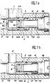
- a valve 1 is intended to control the flow of a pressurized fluid through the passage section defined between two inlet 2 and outlet conduits 3 drilled in a body 4.
- the valve 1 comprises a shutter 5 formed of a tubular element 6, one end face, or front face, is closed by a front wall 7 which is pierced with a central opening 8.
- This opening 8 (FIG. 1a) opens out. in a chamber 9 defined inside the shutter 5 between the front wall 7 and a piston 10 slidably mounted, in leaktight manner by a seal 10a, inside the shutter 5.
- the rear face of the shutter 5 is for example delimited by the annular bottom of an internal axial recess 11 machined in the thickness of the tubular element 6 and on which will come to bear one end of an elastic return element, such as 'a spring 12.
- the shutter 5 of the valve is introduced through its front wall 7 into an open end of the inlet duct 2. More specifically, the shutter 5 is slidably mounted, in leaktight manner by a seal 5a, at the inside the inlet duct 2 until it comes to bear by its front wall 7 on an annular seat 15 machined in the body 4 at the level of the passage section defined between the two conduits 2 and 3.
- the external face 7a of the front wall 7 of the shutter 5 delimits, at its periphery, a frustoconical bearing intended to come into abutment on a bearing surface of conjugate shape delimited at the level of the seat 15 in order to close off the passage section between the two conduits 2 and 3.
- the chamber 9 defined inside the shutter 5 has a cross-sectional area smaller than the surface of the external face 7a of the front wall 7 of the shutter 5 on which the fluid under pressure acts when the valve 1 is closed.
- the return spring 12 is freely mounted around a rod 17 which extends a plug 18 which closes the open end of the inlet conduit 2 through which the valve 1 has been introduced.
- the free end of this rod 17 serves as a bearing surface for the piston 10 housed inside the shutter 5.
- the pressurized fluid which is present in the inlet duct 2 penetrates inside the chamber 9 through the opening 8 of the front wall 7 of the shutter 5.
- the fluid then exerts its pressure at the times on the external face 7a and the internal face 7b of the front wall 7 of the shutter 5. Since the contact surface of the fluid with the face 7a is greater than that of the face 7b, the force which the spring must exert reminder 12 to keep the shutter 5 resting on its seat 15 must only be greater than the difference of the forces exerted simultaneously by the fluid under pressure on the two opposite faces 7a and 7b of its front wall 7.
- valve 1 When the pressure of the fluid in the duct 2 increases and becomes sufficient to cause the shutter 5 to retreat against the force exerted by the spring 12, the valve 1 passes into the open position (FIG. 1b) and releases the passage section defined between the two conduits 2 and 3.
- the increase in the pressure of the fluid in the inlet conduit 2 can result from compression of the fluid obtained by a piston, for example movable inside a fluid storage tank.
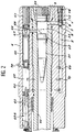
- FIG. 2 partially and schematically illustrates a tube 50 of a medium or large caliber weapon with liquid propellant, with a projectile 51 set at station in the tube 50 at a forcing cone 52, in a manner known per se.
- the rear end of the tube 50 can be sealed in a sealed manner by a breech obturator 53.
- a combustion chamber 55 is delimited in the tube 50 between the projectile 51 and the breech obturator 53 in the closed position thereof.
- This liquid propellant weapon is equipped with an injection system for injecting under pressure into the chamber 55 a propellant, such as a propellant in liquid or gelled form, stored in at least one reservoir 57 defined in an annular body. 4 attached around the tube 50 of the weapon.
- a propellant such as a propellant in liquid or gelled form
- a reservoir 57 defined in an annular body. 4 attached around the tube 50 of the weapon.
- a channel longitudinal 60 is drilled in the body 4 parallel to the axis of the tube 50, and the variable volume reservoir 57 is defined in the channel 60 between two bottoms 61 and 62 respectively constituted by a plug which seals one end of the channel 60, and by a cylindrical element adjustable in axial position inside the channel 60 and which also seals the other end of the latter.
- a pressure multiplier piston 65 is slidably mounted inside the tank 57.
- the bottom 61 formed by the plug is extended inside the tank 57 by an axial stop 66 on which the piston 65 is supported when the tank 57 is filled.
- a chamber 67 is delimited in the reservoir 57 around the stop 66.
- This chamber 67 communicates with the combustion chamber 55 by an inlet pipe 68 formed by a channel pierced in the body 4 and in the wall of the tube 50.
- the tank 57 also communicates with the combustion chamber 55 by an outlet pipe 69 pierced inside the body 4.
- This outlet pipe 69 consists of a longitudinal channel or conduit 2 which communicates with the tank 57 by at least a connection duct 70 and with the combustion chamber 55 via a radial duct 3.
- the volume of the reservoir 57 is adjusted to store the total amount of propellant necessary for firing the projectile 51. This operation consists in adjusting the axial position of the bottom of cylinder 62 by means of an adjustment mechanism 62a. Once the volume of the reservoir 57 has been adjusted, the propellant is sent under low pressure to the reservoir 57 which communicates, for this purpose, through a channel 75 with a filling means (not shown). The propellant spreads through the conduit 2 and enters the chamber 9 of the valve shutter 1.
- valve 1 remains in the closed position with the front wall 7 of the shutter 5 resting on the seat 15 , from the moment when the force exerted by the return spring 12 on the rear face of the shutter 5 is greater than the difference of the forces exerted by the propellant on the two opposite faces 7a and 7b of the front wall Shutter 7 5.
- a small quantity of propellant is injected and then ignited directly in the combustion chamber 55.
- the combustion gases freely penetrate inside the chamber 67 via the inlet pipe 68 and, as soon as their pressure becomes sufficient, they cause the piston 65 to move. This pressure is however insufficient to cause the projectile to be ejected. 51.
- the piston 65 compresses the propellant contained in the reservoir 57 and the associated outlet pipe 69. As soon as the propellant compressed by the piston 65 has reached the pressure necessary to open the valve 1, the latter releases the passage section defined between the two conduits 2 and 3. The agent can then flow up to to the combustion chamber 55 and then cause the projectile 51 to be ejected when the pressure of the combustion gases reaches a sufficient value.
Landscapes
- Engineering & Computer Science (AREA)
- Chemical & Material Sciences (AREA)
- Combustion & Propulsion (AREA)
- Physics & Mathematics (AREA)
- General Engineering & Computer Science (AREA)
- Fluid Mechanics (AREA)
- General Physics & Mathematics (AREA)
- Automation & Control Theory (AREA)
- Nozzles (AREA)
Applications Claiming Priority (2)
| Application Number | Priority Date | Filing Date | Title |
|---|---|---|---|
| FR9213099A FR2697606B1 (fr) | 1992-11-02 | 1992-11-02 | Soupape pour commander l'écoulement d'un fluide sous pression au travers de la section de passage entre deux conduits d'entrée et de sortie. |
| FR9213099 | 1992-11-02 |
Publications (1)
| Publication Number | Publication Date |
|---|---|
| EP0596768A1 true EP0596768A1 (de) | 1994-05-11 |
Family
ID=9435087
Family Applications (1)
| Application Number | Title | Priority Date | Filing Date |
|---|---|---|---|
| EP93402594A Withdrawn EP0596768A1 (de) | 1992-11-02 | 1993-10-22 | Druckfluid-Stromregelventil des Durchgangs zwischen zwei Ein- und Auslassleitungen |
Country Status (2)
| Country | Link |
|---|---|
| EP (1) | EP0596768A1 (de) |
| FR (1) | FR2697606B1 (de) |
Cited By (2)
| Publication number | Priority date | Publication date | Assignee | Title |
|---|---|---|---|---|
| FR2879721A1 (fr) * | 2004-12-22 | 2006-06-23 | Clesse Ind Soc Par Actions Sim | Detendeur de gaz a piston insensible aux variations de pression amont |
| CN108167523A (zh) * | 2018-01-22 | 2018-06-15 | 博纳斯威阀门股份有限公司 | 一种带有内置阻尼系统的消声缓闭止回阀 |
Citations (5)
| Publication number | Priority date | Publication date | Assignee | Title |
|---|---|---|---|---|
| US3138174A (en) * | 1961-11-13 | 1964-06-23 | William V Gilpin | Automatic excess fluid flow valve |
| US4037995A (en) * | 1976-06-10 | 1977-07-26 | General Electric Company | Liquid propellant gun (damper) |
| GB2054757A (en) * | 1979-07-25 | 1981-02-18 | Zahnradfabrik Friedrichshafen | High-pressure pump with pressure regulator |
| EP0096523A1 (de) * | 1982-06-01 | 1983-12-21 | Martonair Limited | Druckregler |
| EP0434092A2 (de) * | 1989-12-21 | 1991-06-26 | Sumitomo Electric Industries, Ltd. | Stromregelventil |
-
1992
- 1992-11-02 FR FR9213099A patent/FR2697606B1/fr not_active Expired - Fee Related
-
1993
- 1993-10-22 EP EP93402594A patent/EP0596768A1/de not_active Withdrawn
Patent Citations (5)
| Publication number | Priority date | Publication date | Assignee | Title |
|---|---|---|---|---|
| US3138174A (en) * | 1961-11-13 | 1964-06-23 | William V Gilpin | Automatic excess fluid flow valve |
| US4037995A (en) * | 1976-06-10 | 1977-07-26 | General Electric Company | Liquid propellant gun (damper) |
| GB2054757A (en) * | 1979-07-25 | 1981-02-18 | Zahnradfabrik Friedrichshafen | High-pressure pump with pressure regulator |
| EP0096523A1 (de) * | 1982-06-01 | 1983-12-21 | Martonair Limited | Druckregler |
| EP0434092A2 (de) * | 1989-12-21 | 1991-06-26 | Sumitomo Electric Industries, Ltd. | Stromregelventil |
Cited By (4)
| Publication number | Priority date | Publication date | Assignee | Title |
|---|---|---|---|---|
| FR2879721A1 (fr) * | 2004-12-22 | 2006-06-23 | Clesse Ind Soc Par Actions Sim | Detendeur de gaz a piston insensible aux variations de pression amont |
| WO2006070116A3 (fr) * | 2004-12-22 | 2007-01-25 | Clesse Ind | Detendeur de gaz a piston insensible aux variations de pression amont |
| CN108167523A (zh) * | 2018-01-22 | 2018-06-15 | 博纳斯威阀门股份有限公司 | 一种带有内置阻尼系统的消声缓闭止回阀 |
| CN108167523B (zh) * | 2018-01-22 | 2023-10-31 | 博纳斯威阀门股份有限公司 | 一种带有内置阻尼系统的消声缓闭止回阀 |
Also Published As
| Publication number | Publication date |
|---|---|
| FR2697606B1 (fr) | 1995-01-13 |
| FR2697606A1 (fr) | 1994-05-06 |
Similar Documents
| Publication | Publication Date | Title |
|---|---|---|
| BE1007314A3 (fr) | Arme a feu perfectionnee. | |
| EP0225225A1 (de) | Ventil zum Aufladen und nachfolgenden schnellen Entladen eines Behälters | |
| FR2492473A1 (fr) | Pompe a membrane a compensation dans la chambre hydraulique de commande | |
| FR2834016A1 (fr) | Pompe a jet | |
| EP0420720B1 (de) | Druckgasgefäss mit kontrollierter Gasabgabe | |
| FR2714165A1 (fr) | Système de contre-masse dispersable pour arme sans recul. | |
| EP0519785B1 (de) | Schlagbolzenanordnung für Feuerwaffe | |
| EP1151236A1 (de) | Vorrrichtung zur verringerung des rückstosses mit bremse, bremskompensator und rohrvorholer | |
| EP0596768A1 (de) | Druckfluid-Stromregelventil des Durchgangs zwischen zwei Ein- und Auslassleitungen | |
| EP0107117B1 (de) | Hydropneumatische Rückstossbremse mit Energierückgewinnung für Artilleriegeschütze und Handfeuerwaffen | |
| EP0596759A1 (de) | Feuerwaffe mit flüssiger Treibladung | |
| EP0619868B1 (de) | Dämpfung des kolbens eines geschützes für flüssigkeitstreibmittel | |
| FR2642827A1 (fr) | Dispositif d'etancheite pour systeme a piston a pression differentielle et a chambre de combustion | |
| FR2711433A1 (fr) | Régulateur coaxial de débit. | |
| FR2708069A1 (fr) | Joint d'étanchéité statique. | |
| FR2708070A1 (fr) | Joint d'étanchéité en statique et en dynamique. | |
| EP2623918B1 (de) | Pneumatische abschussvorrichtung | |
| FR2684438A1 (fr) | Canon utilisant une charge propulsive liquide. | |
| FR2677741A1 (fr) | Canon a injection regeneratrice d'ergol liquide. | |
| FR2635859A1 (fr) | Perfectionnements aux systemes d'armes a propulseur liquide | |
| FR2770261A1 (fr) | Dispositif de limitation de debit de carburant pour moteur a combustion interne a injection | |
| EP0661513A1 (de) | Treibanordnung für Geschosse | |
| FR2666881A1 (fr) | Dispositif d'injection d'agent de propulsion fluide dans des canons, et canon a fluide. | |
| EP0687887A1 (de) | Vorrichtung zum Ausgleich eines Geschützrohres | |
| FR2889260A3 (fr) | Rampe commune d'alimentation en carburant pour moteur, comprenant deux chambres |
Legal Events
| Date | Code | Title | Description |
|---|---|---|---|
| PUAI | Public reference made under article 153(3) epc to a published international application that has entered the european phase |
Free format text: ORIGINAL CODE: 0009012 |
|
| AK | Designated contracting states |
Kind code of ref document: A1 Designated state(s): DE GB |
|
| STAA | Information on the status of an ep patent application or granted ep patent |
Free format text: STATUS: THE APPLICATION IS DEEMED TO BE WITHDRAWN |
|
| 18D | Application deemed to be withdrawn |
Effective date: 19941112 |