EP0596776A1 - Kontaktleiste mit anpassbarer Etikettierung - Google Patents
Kontaktleiste mit anpassbarer Etikettierung Download PDFInfo
- Publication number
- EP0596776A1 EP0596776A1 EP93402644A EP93402644A EP0596776A1 EP 0596776 A1 EP0596776 A1 EP 0596776A1 EP 93402644 A EP93402644 A EP 93402644A EP 93402644 A EP93402644 A EP 93402644A EP 0596776 A1 EP0596776 A1 EP 0596776A1
- Authority
- EP
- European Patent Office
- Prior art keywords
- strip
- label holder
- lateral
- face
- front face
- Prior art date
- Legal status (The legal status is an assumption and is not a legal conclusion. Google has not performed a legal analysis and makes no representation as to the accuracy of the status listed.)
- Granted
Links
- 238000002372 labelling Methods 0.000 title description 2
- 230000000295 complement effect Effects 0.000 claims description 5
- 239000004020 conductor Substances 0.000 description 10
- 229920003023 plastic Polymers 0.000 description 4
- 239000000463 material Substances 0.000 description 2
- 239000002184 metal Substances 0.000 description 2
- 239000011347 resin Substances 0.000 description 2
- 229920005989 resin Polymers 0.000 description 2
- 230000000717 retained effect Effects 0.000 description 2
- 238000001125 extrusion Methods 0.000 description 1
- 230000035515 penetration Effects 0.000 description 1
- XLYOFNOQVPJJNP-UHFFFAOYSA-N water Chemical compound O XLYOFNOQVPJJNP-UHFFFAOYSA-N 0.000 description 1
Images

Classifications
-
- H—ELECTRICITY
- H01—ELECTRIC ELEMENTS
- H01R—ELECTRICALLY-CONDUCTIVE CONNECTIONS; STRUCTURAL ASSOCIATIONS OF A PLURALITY OF MUTUALLY-INSULATED ELECTRICAL CONNECTING ELEMENTS; COUPLING DEVICES; CURRENT COLLECTORS
- H01R9/00—Structural associations of a plurality of mutually-insulated electrical connecting elements, e.g. terminal strips or terminal blocks; Terminals or binding posts mounted upon a base or in a case; Bases therefor
- H01R9/22—Bases, e.g. strip, block, panel
- H01R9/24—Terminal blocks
- H01R9/26—Clip-on terminal blocks for side-by-side rail- or strip-mounting
- H01R9/2683—Marking plates or tabs
-
- H—ELECTRICITY
- H04—ELECTRIC COMMUNICATION TECHNIQUE
- H04Q—SELECTING
- H04Q1/00—Details of selecting apparatus or arrangements
- H04Q1/02—Constructional details
- H04Q1/021—Constructional details using pivoting mechanisms for accessing the interior of the apparatus
-
- H—ELECTRICITY
- H04—ELECTRIC COMMUNICATION TECHNIQUE
- H04Q—SELECTING
- H04Q1/00—Details of selecting apparatus or arrangements
- H04Q1/02—Constructional details
- H04Q1/14—Distribution frames
- H04Q1/146—Distribution frames with line protection means
-
- H—ELECTRICITY
- H04—ELECTRIC COMMUNICATION TECHNIQUE
- H04Q—SELECTING
- H04Q1/00—Details of selecting apparatus or arrangements
- H04Q1/02—Constructional details
- H04Q1/14—Distribution frames
- H04Q1/148—Identification strips for distribution frames
-
- H—ELECTRICITY
- H01—ELECTRIC ELEMENTS
- H01R—ELECTRICALLY-CONDUCTIVE CONNECTIONS; STRUCTURAL ASSOCIATIONS OF A PLURALITY OF MUTUALLY-INSULATED ELECTRICAL CONNECTING ELEMENTS; COUPLING DEVICES; CURRENT COLLECTORS
- H01R13/00—Details of coupling devices of the kinds covered by groups H01R12/70 or H01R24/00 - H01R33/00
- H01R13/46—Bases; Cases
- H01R13/465—Identification means, e.g. labels, tags, markings
Definitions
- the present invention relates to a contact strip with adaptable labeling.
- the invention relates to a contact strip of the cable head type, which is commonly found in telephone, office or domestic distributors.
- a contact strip of the cable head type, which is commonly found in telephone, office or domestic distributors.
- Such a strip comprises at least one row of contacts which are connected, on the one hand to the conductors of a cable, and on the other hand to jumpers as is well known.
- the document EP-0 133 824 illustrates for example such contact strips.
- the aforementioned distributors can include a large number of contact strips, it is desirable to label the strips to identify them.
- the strips are usually juxtaposed along a fixing rail and arranged in such a way that only their front face is clearly visible, on which the contacts are arranged, so that in the prior art, the strips were identified by means of '' labels carried by a label holder snapped onto the front of the strip, in front of the contacts.
- PCT patent application no. WO-A-8 503 800 discloses a marking device as well as an electrical component capable of receiving said marking device on its inclined side faces.
- the marking device described consists of a piece of elastic resin substantially U-shaped intended to be snapped either on a cable, or on or between ribs specially provided on said inclined side faces of the electrical connector.
- the marking consists of symbols such as letters or numbers visible on the central part of the U connecting the two branches.
- a series of removable marking devices can be snapped onto each inclined lateral face of the electrical connector so as to constitute an inscription or a reference.
- Each piece of elastic resin is made by extrusion, then marked with a symbol (number or letter). To constitute a reference, it is therefore necessary to be provided with a wide variety of symbols.
- a contact strip having two generally flat planar sides substantially rectangular, two lateral faces, a front face and a rear face, said contact strip being adapted to be fixed to a rail. by said rear face, said sides being perpendicular to the longitudinal direction of the rail, said front face comprising electrical contacts, said contact strip comprising a lateral label holder extending on a lateral face and forming an obtuse angle with the front face so that a label carried by said label holder is visible from the front face of the contact strip, characterized in that the lateral label holder comprises latching means at one of its ends cooperating with a latching member provided on the front face at one of its ends near the side face to mount amo visible said label holder on the strip.
- Another technical problem is to allow access to the lateral face of the strip which comprises the lateral label holder, for example for connecting a cable screen drain to the ground, as illustrated for example in the document FR-A- 2,650,709, without having to dismantle the side label holder, which would then risk not being reassembled later or which could be reversed with another label holder.
- this problem is solved in that the lateral label holder substantially covers said lateral face, and said lateral label holder is rotatably mounted around an axis close to the front face of the strip and perpendicular to the sides of the slider.
- Another technical problem is to allow simultaneous mounting of the side label holder and a front label holder of the type of that of the prior art, without complicating the contact strip.
- the contact strip has identical snap members at the two ends of its front face close to the lateral faces
- said strip also comprises a label holder front which covers the front face of the strip and which is fitted with latching means cooperating with one of the latching members for removably mounting the front label holder on the strip.
- Another technical problem is to allow access to the front face of the contact strip, for example to connect jumper conductors to the electrical contacts of the front face, and this without removing the front label holder, which would then risk not to be subsequently reassembled or which could be inverted with another label holder.
- this technical problem is solved in that the latching means of the front label holder cooperate with one of the members for rotary mounting of the front label holder around an axis perpendicular to the sides of the strip.
- each latching member provided at each end of the front face comprises two identical bosses each having the shape of a plate which extends parallel to the sides of the strip, said two bosses forming a bearing for mounting rotating a front or side label holder.
- each lateral boss is elastically deformable perpendicularly to the sides of the strip, and comprises a hole for receiving by snap-fastening a pivot secured to a front or lateral label holder.
- Another technical problem is to produce a side label holder which is common to several strips.
- said lateral label holder is a generally C-shaped section
- the strip has a lateral boss of complementary shape on at least one of its two lateral faces, in the vicinity of the front face, said lateral label holder is snapped onto said lateral boss and extends perpendicularly to the sides of the strip, beyond beyond at least one of said sides.
- said lateral boss has a groove perpendicular to the sides of the strip, and said lateral label holder has a complementary rib snapped into said groove.
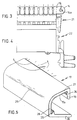
- FIG. 1 represents a strip of contacts of known type.
- the strip has two sides 4 of generally rectangular planar shape, two lateral faces 5, 6, a front face 7 and a rear face 8.
- the strip 1 is snapped on by its rear face 8 on a rail 2 generally metallic, and it comprises its front face one or more rows of contacts 3, which are generally self-stripping type contacts, well known in the state of the art, for example double self-stripping contacts as disclosed in document FR-A- 2 664 433.
- the self-stripping contacts 3 are connected to the conductor of a cable (not shown) which may be a telephone cable, or a data link cable or the like.
- the sides 4 of the strip 1 can advantageously be constituted by flanges provided with internal guide channels for guiding the various conductors of the cable.
- the self-stripping contacts 3 are connected to garters, that is to say to conductors which make it possible to carry out patching within a telephone, computer or other distributor.
- the jumpers can be individual conductors 9, which are engaged individually in the slots of the self-stripping contacts 3, but the jumpers can also be constituted by cables 11 terminated by a plug 10 which plugs into the self-stripping contacts 3 .
- a large number of strips 1 are snapped next to each other on one or more rails 2.
- the strips are generally in contact with or in the vicinity of each other by their sides 4. Due to the large number of strips within a distributor, it is necessary to label the different strips to be able to identify them. Given the arrangement of the strips, it is usual to cover the front face 7 of the strip with a label holder 20 snapped onto the strip.
- a label holder is compatible with the individual conductors 9 fixed on the various self-stripping contacts, but is not compatible with a jumper formed by a cable 11 and a connector 10, due to the size of the connector and the cable.
- a connector 10 on the front face of the strip it is necessary to remove the label holder 20, so that the strip is no longer identified, which is very annoying.
- FIG. 2 represents a contact strip 1 according to the present invention, which has a general shape similar to that of FIG. 1, and which will not be described again in detail here.
- the references used for figure 1 will be used for figure 2 and the following figures, to designate elements identical or similar to those of figure 1.
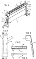
- the contact strip 1 comprises two central parts 21, 22 made of plastic material shown in FIGS. 3 and 4, and which are assembled by snap-fastening, as shown in FIG. 5.
- the strip also comprises two lateral flanges 23 made of plastic material, shown in Figure 2, said side flanges 23 forming the sides 4 of the strip.
- the flanges 23 have internal guide channels (not shown) for guiding the various conductors of a cable connected to the strip 1.
- the strip has on each of its lateral faces 5, 6, a quick-contact earth contact 24, preferably in the form of an elastic clamp, which makes it possible to connect the screen drain of a cable associated with the strip 1 to earth.
- the earth contact 24 is generally in electrical contact with the rail 2, for example by a metal tongue projecting from the rear face 8 of the strip (not shown), said metal rail 2 being itself connected to earth.
- Each lateral face 5, 6 of the strip further comprises, in the vicinity of the front face 7 of the strip, two bosses 14 which project laterally outwards.
- Each boss 14 is formed in the vicinity of one side 4 of the strip and has the form of a plate parallel to said side 4 of the strip.
- Each of the bosses 14 has a hole 14a perpendicular to the sides 4 of the strip, the holes 14a of the two bosses 14 which are located on the same lateral face of the strip being aligned.
- the bosses 14 have a certain elasticity in the direction perpendicular to the side 4 of the strip.
- the bosses 14 each have a notch 19 at the front face 7 of the strip, the said notches 19 of the two bosses 14 on the same side face of the strip being aligned perpendicularly to the sides 4 of the strip.
- the strip 1 according to the invention can be provided with different label holders.
- the rule can be provided with a front label holder 13, which can be made of transparent plastic and which contains one or more labels 13a.
- the label holder 13 has two pivots 16 adapted to snap into the holes 14a of two bosses 14 of one of the side faces of the strip, for example the side face 6.
- the door -Front label 13 is thus rotatably mounted on the bosses 14, so as to be able to disengage the front face 7 of the strip when it must be accessed, for example, to fix or remove a conductor 9, or to test one of the contacts 3 , without having to dismantle the front label holder 13 from the strip 1.
- the label holder 13 internally has hooking members 13b allowing the label 13a to be hung.
- the label holder 13 extends to the vicinity of the bosses 14 on the other side face of the strip, but without overflowing on said bosses 14.
- the bosses 14 on the other side face can accommodate a side label holder 12, having a label 12a which may be similar to the label 13a of the front label holder.
- the label holder 12 is shown in Figures 7 and 8, and has two pivots 15 adapted to snap into the holes 14a of the bosses of the side face 5 of the strip.
- the label holder 12 further comprises hooking members 12b which allow the label 12a to be retained.
- the side label holder 12 In the normal position, the side label holder 12 is inclined relative to the side face 5, so as to move away from said side face away from the front face 7 of the strip. Thus one can easily read the label 12a by being in front of the front face 7 of the strip.
- the label holder 12 As the lateral label holder 12 is rotatably mounted in the bosses 14, the label holder 12 can be rotated around its pivots 15, so as to bring the label 12a into a position parallel to the front face 7 of the strip, to better read said label 12a.
- the rotary mounting of the lateral label holder 12, which can extend substantially over the entire lateral face 5 of the strip makes it possible to release the earth contact 24 when a screen screen drain has to be connected to it. a cable. When one wants to connect to the contacts 3 of the strip a connector 10 associated with a cable 11, one can either raise the label holder 13 and leave it in the raised position, or remove said front label holder 13, in which case the strip 1 remains identified by the side label holder 12.
- the side label holder 12 can be replaced by a fixed side label holder 17, shown in FIG. 6.
- the label holder 17 in FIG. 6 is a transparent plastic profile in the general shape of C, of substantially complementary shape. bosses 14 which can engage said bosses 14, said label holder 17 having a rib 18 adapted to snap into the notches 19 of the bosses 14.
- the label holder 17 has a bottom 28 substantially parallel to the face lateral 6, or possibly inclined away from the lateral face towards the rear.
- the bottom 28 is extended substantially at a right angle towards the strip by a rear branch 30, and at an angle towards the strip and forwards by a front branch 27, which ends in the rib 18 substantially parallel to the side face 5.
- the branch 27 can be connected to the bottom 28 by a rounded 29.
- the branch 27 could possibly be substantially parallel to the front face of the strip.
- the label holder 17 can have a relatively large length, and extend over the lateral faces 5 of several contact strips 1, when several contact strips need to have a common marking.
- the label holder 17 comprises a label 17a, placed inside the C-shaped profile, against the branch 27 of the C which is directed towards the front and against the bottom 28 of the C.
- the label 17a is retained by interior reliefs 25, 26. As before, the label 17a is fairly easily readable from the front of the strip 1.
- the slider according to the invention could also include two rotary side label holders 12, or two fixed side label holders 17, on the two lateral faces of the strip.
- the front label holder 13 already described can close the front face of the strip in a substantially leaktight manner, to avoid, for example, the penetration of water vapor onto the contacts 3.
Landscapes
- Engineering & Computer Science (AREA)
- Computer Networks & Wireless Communication (AREA)
- Details Of Connecting Devices For Male And Female Coupling (AREA)
- Labeling Devices (AREA)
- Electric Cable Installation (AREA)
- Insulated Conductors (AREA)
- Connections Arranged To Contact A Plurality Of Conductors (AREA)
- Clamps And Clips (AREA)
Applications Claiming Priority (2)
| Application Number | Priority Date | Filing Date | Title |
|---|---|---|---|
| FR9213108 | 1992-11-02 | ||
| FR9213108A FR2697708B1 (fr) | 1992-11-02 | 1992-11-02 | Réglette à contacts avec étiquetage adaptable. |
Publications (2)
| Publication Number | Publication Date |
|---|---|
| EP0596776A1 true EP0596776A1 (de) | 1994-05-11 |
| EP0596776B1 EP0596776B1 (de) | 1998-07-08 |
Family
ID=9435096
Family Applications (1)
| Application Number | Title | Priority Date | Filing Date |
|---|---|---|---|
| EP93402644A Expired - Lifetime EP0596776B1 (de) | 1992-11-02 | 1993-10-28 | Kontaktleiste mit anpassbarer Etikettierung |
Country Status (6)
| Country | Link |
|---|---|
| US (1) | US5419715A (de) |
| EP (1) | EP0596776B1 (de) |
| JP (1) | JPH06208868A (de) |
| DE (1) | DE69319543T2 (de) |
| ES (1) | ES2119875T3 (de) |
| FR (1) | FR2697708B1 (de) |
Cited By (1)
| Publication number | Priority date | Publication date | Assignee | Title |
|---|---|---|---|---|
| EP2490237B1 (de) * | 2011-02-17 | 2018-10-17 | Abb Ag | Wechselschild für Reiheneinbaugeräte |
Families Citing this family (14)
| Publication number | Priority date | Publication date | Assignee | Title |
|---|---|---|---|---|
| DE19648351A1 (de) * | 1996-11-22 | 1998-05-28 | Wieland Electric Gmbh | Dezentrales Eingabe-/Ausgabemodul für einen Datenbus |
| US6140796A (en) * | 1997-08-07 | 2000-10-31 | Martin Safety Products Co. | Battery jump-start safety system and process |
| GB2380869B (en) * | 2001-10-06 | 2005-04-20 | Mayall & Co Ltd | A connector having a label mounting means |
| US6718674B2 (en) * | 2002-03-21 | 2004-04-13 | Panduit Corp. | Apparatus and system for identification labeling |
| GB0207366D0 (en) * | 2002-03-28 | 2002-05-08 | Mayall & Co Ltd | Improvements relating to electrical connectors |
| DE102007050589B4 (de) * | 2007-10-23 | 2009-06-25 | Adc Gmbh | Leiterplattensteckverbinder |
| US8413679B2 (en) * | 2008-04-15 | 2013-04-09 | Festo Ag & Co. Kg | Modular control device, especially of an electro-fluidic type |
| ITMI20100017U1 (it) * | 2010-01-28 | 2011-07-29 | Morsettitalia Spa | Morsetto di collegamento elettrico da quadro con alloggiamento porta etichetta, etichetta per detto alloggiamento e relativo assieme morsetto/etichetta |
| CN102403580B (zh) * | 2010-09-15 | 2015-01-14 | 进联电子科技(上海)有限公司 | 接合器及具有该接合器的导线端子座结构 |
| US9225155B1 (en) * | 2013-09-04 | 2015-12-29 | James B. Rauckman | Safety cover and identifier for electric terminal block |
| US9385517B2 (en) * | 2014-04-02 | 2016-07-05 | Busway Solutions, LLC | Busway output box guide/inhibitor system for insertion and removal of a busway output box |
| US10062979B2 (en) * | 2015-08-21 | 2018-08-28 | Panduit Corp. | Terminal block marker |
| EP3425742B1 (de) * | 2017-07-07 | 2023-03-01 | Morsettitalia S.p.A. | Schaltanlage klemmleisten mit mehreren etikettenhaltersitzen |
| EP4080691A1 (de) * | 2021-04-23 | 2022-10-26 | Zumtobel Lighting GmbH | Tragschiene für leuchten oder elektrische einheiten |
Citations (4)
| Publication number | Priority date | Publication date | Assignee | Title |
|---|---|---|---|---|
| DE3324652C1 (de) * | 1983-07-08 | 1984-10-18 | C.A. Weidmüller GmbH & Co, 4930 Detmold | Reihenklemmenblock |
| DE3615824A1 (de) * | 1985-05-13 | 1986-11-13 | Allen-Bradley Co. Inc., Milwaukee, Wis. | Elektrischer anschlussblock |
| DE3929905C1 (en) * | 1989-09-08 | 1990-10-31 | F. Wieland Elektrische Industrie Gmbh, 8600 Bamberg, De | Terminal strip marking arrangement - has vertical support plates for row of terminals mounted in switch cabinet |
| FR2665044A1 (fr) * | 1990-07-23 | 1992-01-24 | Sofycom | Dispositif porte-etiquette pour repartiteur telephonique. |
Family Cites Families (7)
| Publication number | Priority date | Publication date | Assignee | Title |
|---|---|---|---|---|
| GB911303A (en) * | 1959-04-02 | 1962-11-21 | Leslie Emil Lanczi | Improvements in or relating to electric terminal blocks |
| US3247480A (en) * | 1963-07-01 | 1966-04-19 | Buchanan Electrical Prod Corp | Terminal block cover |
| DE2033182C3 (de) * | 1970-07-04 | 1973-09-20 | Phoenix Elektrizitaetsgesellschaft H. Knuemann & Co., 4933 Blomberg | Vielpolige elektrotechnische Klemmvorrichtung |
| US3753216A (en) * | 1971-10-14 | 1973-08-14 | Amp Inc | High voltage terminal strip |
| SE8400888D0 (sv) * | 1984-02-17 | 1984-02-17 | Partex Fabriks Ab | Anordning for merkning av elektriska ledningar och komponenter |
| US4550964A (en) * | 1984-07-23 | 1985-11-05 | The Siemon Company | Hinged cover and label assembly for connector block |
| US5080607A (en) * | 1990-05-24 | 1992-01-14 | Northern Telecom Limited | Support member for a designation label for terminals of a cross-connect connector |
-
1992
- 1992-11-02 FR FR9213108A patent/FR2697708B1/fr not_active Expired - Fee Related
-
1993
- 1993-10-28 EP EP93402644A patent/EP0596776B1/de not_active Expired - Lifetime
- 1993-10-28 DE DE69319543T patent/DE69319543T2/de not_active Expired - Fee Related
- 1993-10-28 US US08/142,136 patent/US5419715A/en not_active Expired - Fee Related
- 1993-10-28 ES ES93402644T patent/ES2119875T3/es not_active Expired - Lifetime
- 1993-11-02 JP JP5295943A patent/JPH06208868A/ja not_active Withdrawn
Patent Citations (4)
| Publication number | Priority date | Publication date | Assignee | Title |
|---|---|---|---|---|
| DE3324652C1 (de) * | 1983-07-08 | 1984-10-18 | C.A. Weidmüller GmbH & Co, 4930 Detmold | Reihenklemmenblock |
| DE3615824A1 (de) * | 1985-05-13 | 1986-11-13 | Allen-Bradley Co. Inc., Milwaukee, Wis. | Elektrischer anschlussblock |
| DE3929905C1 (en) * | 1989-09-08 | 1990-10-31 | F. Wieland Elektrische Industrie Gmbh, 8600 Bamberg, De | Terminal strip marking arrangement - has vertical support plates for row of terminals mounted in switch cabinet |
| FR2665044A1 (fr) * | 1990-07-23 | 1992-01-24 | Sofycom | Dispositif porte-etiquette pour repartiteur telephonique. |
Cited By (1)
| Publication number | Priority date | Publication date | Assignee | Title |
|---|---|---|---|---|
| EP2490237B1 (de) * | 2011-02-17 | 2018-10-17 | Abb Ag | Wechselschild für Reiheneinbaugeräte |
Also Published As
| Publication number | Publication date |
|---|---|
| JPH06208868A (ja) | 1994-07-26 |
| EP0596776B1 (de) | 1998-07-08 |
| DE69319543D1 (de) | 1998-08-13 |
| FR2697708A1 (fr) | 1994-05-06 |
| ES2119875T3 (es) | 1998-10-16 |
| US5419715A (en) | 1995-05-30 |
| FR2697708B1 (fr) | 1994-12-23 |
| DE69319543T2 (de) | 1999-04-15 |
Similar Documents
| Publication | Publication Date | Title |
|---|---|---|
| EP0596776B1 (de) | Kontaktleiste mit anpassbarer Etikettierung | |
| FR2824960A1 (fr) | Dispositif de raccordement a poussoir | |
| EP0123590A1 (de) | Verbinder | |
| FR2776426A1 (fr) | Element de raccordement de deux fiches, elements male et femelle adaptes et dispositif de raccordement obtenu | |
| FR2580432A1 (fr) | Connecteur de liaison pour conducteurs electriques | |
| EP1018191A1 (de) | Schwachstromstecker mit organisations-rückverschlusskappe | |
| FR2514560A1 (fr) | Ensemble de support de circuit integre | |
| EP0911907A1 (de) | Verbindungsmodul für zwei monopaarige Linien | |
| EP1271713B1 (de) | Schwachstrom-Modular Jackverbinder | |
| FR2504315A1 (fr) | Element de connexion et dispositif de connexion, comportant de tels elements | |
| FR2517476A1 (fr) | Systeme de raccordement electrique et element de connecteur | |
| FR2531577A1 (fr) | Contact electrique a pression a pouvoir de fermeture et d'ouverture incorpore | |
| EP0272189B2 (de) | Verbinder für elektrisches Gerät zum Einrasten auf eine Montageschiene, und elektrisches Gerät geeignet für die Ausführung eines solchen Verbinders | |
| EP0556085A1 (de) | Steckverbindung-Zusammenbau zwischen einer Mutterschaltung und einer Tochterschaltung | |
| EP0599701A1 (de) | Kommunikationssystem mit Kontaktleiste für Kommunikationen mit hohen Datenfluss | |
| FR2510821A1 (fr) | Bloc de raccordement pour lignes de telecommunications | |
| FR2575609A1 (fr) | Borne de connexion pour cables metalliques | |
| FR2778502A1 (fr) | Connecteur electrique a grille de protection des contacts | |
| EP0642193A1 (de) | Schneidklemmverbinder | |
| EP0744088A1 (de) | Elektrische stecker in englischer ausführung | |
| FR2611315A1 (fr) | Bloc de bornes pour le raccordement de conducteurs electriques | |
| FR2519222A1 (fr) | Dispositif de raccordement polyvalent pour repartiteur de central telephonique | |
| FR2521788A1 (fr) | Connecteur pour cartes a circuits imprimes | |
| FR3115637A1 (fr) | Connecteur pour la connexion d’une terminaison électrique sur un circuit imprimé, procédés d’assemblage correspondants. | |
| EP0489642B1 (de) | Vorverdrahtbare Anschlussleiste |
Legal Events
| Date | Code | Title | Description |
|---|---|---|---|
| PUAI | Public reference made under article 153(3) epc to a published international application that has entered the european phase |
Free format text: ORIGINAL CODE: 0009012 |
|
| AK | Designated contracting states |
Kind code of ref document: A1 Designated state(s): DE ES FR GB IT |
|
| 17P | Request for examination filed |
Effective date: 19941020 |
|
| GRAG | Despatch of communication of intention to grant |
Free format text: ORIGINAL CODE: EPIDOS AGRA |
|
| GRAG | Despatch of communication of intention to grant |
Free format text: ORIGINAL CODE: EPIDOS AGRA |
|
| GRAH | Despatch of communication of intention to grant a patent |
Free format text: ORIGINAL CODE: EPIDOS IGRA |
|
| 17Q | First examination report despatched |
Effective date: 19971205 |
|
| GRAH | Despatch of communication of intention to grant a patent |
Free format text: ORIGINAL CODE: EPIDOS IGRA |
|
| GRAA | (expected) grant |
Free format text: ORIGINAL CODE: 0009210 |
|
| AK | Designated contracting states |
Kind code of ref document: B1 Designated state(s): DE ES FR GB IT |
|
| REF | Corresponds to: |
Ref document number: 69319543 Country of ref document: DE Date of ref document: 19980813 |
|
| GBT | Gb: translation of ep patent filed (gb section 77(6)(a)/1977) |
Effective date: 19980731 |
|
| REG | Reference to a national code |
Ref country code: ES Ref legal event code: FG2A Ref document number: 2119875 Country of ref document: ES Kind code of ref document: T3 |
|
| PLBE | No opposition filed within time limit |
Free format text: ORIGINAL CODE: 0009261 |
|
| STAA | Information on the status of an ep patent application or granted ep patent |
Free format text: STATUS: NO OPPOSITION FILED WITHIN TIME LIMIT |
|
| 26N | No opposition filed | ||
| PGFP | Annual fee paid to national office [announced via postgrant information from national office to epo] |
Ref country code: GB Payment date: 20001013 Year of fee payment: 8 |
|
| PGFP | Annual fee paid to national office [announced via postgrant information from national office to epo] |
Ref country code: DE Payment date: 20001017 Year of fee payment: 8 |
|
| PGFP | Annual fee paid to national office [announced via postgrant information from national office to epo] |
Ref country code: FR Payment date: 20001027 Year of fee payment: 8 |
|
| PGFP | Annual fee paid to national office [announced via postgrant information from national office to epo] |
Ref country code: ES Payment date: 20001030 Year of fee payment: 8 |
|
| PG25 | Lapsed in a contracting state [announced via postgrant information from national office to epo] |
Ref country code: GB Free format text: LAPSE BECAUSE OF NON-PAYMENT OF DUE FEES Effective date: 20011028 |
|
| PG25 | Lapsed in a contracting state [announced via postgrant information from national office to epo] |
Ref country code: ES Free format text: LAPSE BECAUSE OF NON-PAYMENT OF DUE FEES Effective date: 20011029 |
|
| REG | Reference to a national code |
Ref country code: GB Ref legal event code: IF02 |
|
| GBPC | Gb: european patent ceased through non-payment of renewal fee |
Effective date: 20011028 |
|
| PG25 | Lapsed in a contracting state [announced via postgrant information from national office to epo] |
Ref country code: FR Free format text: LAPSE BECAUSE OF NON-PAYMENT OF DUE FEES Effective date: 20020628 |
|
| PG25 | Lapsed in a contracting state [announced via postgrant information from national office to epo] |
Ref country code: DE Free format text: LAPSE BECAUSE OF NON-PAYMENT OF DUE FEES Effective date: 20020702 |
|
| REG | Reference to a national code |
Ref country code: FR Ref legal event code: ST |
|
| REG | Reference to a national code |
Ref country code: ES Ref legal event code: FD2A Effective date: 20021113 |
|
| PG25 | Lapsed in a contracting state [announced via postgrant information from national office to epo] |
Ref country code: IT Free format text: LAPSE BECAUSE OF NON-PAYMENT OF DUE FEES;WARNING: LAPSES OF ITALIAN PATENTS WITH EFFECTIVE DATE BEFORE 2007 MAY HAVE OCCURRED AT ANY TIME BEFORE 2007. THE CORRECT EFFECTIVE DATE MAY BE DIFFERENT FROM THE ONE RECORDED. Effective date: 20051028 |