EP0596793A1 - System zur Positionsidentifizierung einer Leitung in einem Wasserbehälter eines Dampferzeugers und Verfahren dazu - Google Patents
System zur Positionsidentifizierung einer Leitung in einem Wasserbehälter eines Dampferzeugers und Verfahren dazu Download PDFInfo
- Publication number
- EP0596793A1 EP0596793A1 EP93402688A EP93402688A EP0596793A1 EP 0596793 A1 EP0596793 A1 EP 0596793A1 EP 93402688 A EP93402688 A EP 93402688A EP 93402688 A EP93402688 A EP 93402688A EP 0596793 A1 EP0596793 A1 EP 0596793A1
- Authority
- EP
- European Patent Office
- Prior art keywords
- image
- camera
- tube
- water box
- steam generator
- Prior art date
- Legal status (The legal status is an assumption and is not a legal conclusion. Google has not performed a legal analysis and makes no representation as to the accuracy of the status listed.)
- Granted
Links
- XLYOFNOQVPJJNP-UHFFFAOYSA-N water Substances O XLYOFNOQVPJJNP-UHFFFAOYSA-N 0.000 title claims abstract description 37
- 238000000034 method Methods 0.000 title claims abstract description 13
- 238000012545 processing Methods 0.000 claims description 12
- 238000004364 calculation method Methods 0.000 claims description 11
- 239000003550 marker Substances 0.000 abstract description 3
- 230000000007 visual effect Effects 0.000 abstract description 2
- 238000005286 illumination Methods 0.000 abstract 2
- 230000003287 optical effect Effects 0.000 description 6
- 238000012800 visualization Methods 0.000 description 6
- 230000002950 deficient Effects 0.000 description 5
- 230000006870 function Effects 0.000 description 5
- 230000005540 biological transmission Effects 0.000 description 4
- 238000004422 calculation algorithm Methods 0.000 description 3
- 238000010586 diagram Methods 0.000 description 3
- 235000021183 entrée Nutrition 0.000 description 3
- 238000005192 partition Methods 0.000 description 3
- 241000130993 Scarabaeus <genus> Species 0.000 description 2
- 241001080024 Telles Species 0.000 description 2
- 238000004458 analytical method Methods 0.000 description 2
- 239000012530 fluid Substances 0.000 description 2
- 238000009434 installation Methods 0.000 description 2
- 230000010354 integration Effects 0.000 description 2
- 238000012360 testing method Methods 0.000 description 2
- ZOXJGFHDIHLPTG-UHFFFAOYSA-N Boron Chemical compound [B] ZOXJGFHDIHLPTG-UHFFFAOYSA-N 0.000 description 1
- 230000006978 adaptation Effects 0.000 description 1
- 229910052796 boron Inorganic materials 0.000 description 1
- 238000011109 contamination Methods 0.000 description 1
- 230000001419 dependent effect Effects 0.000 description 1
- 238000001514 detection method Methods 0.000 description 1
- 238000005516 engineering process Methods 0.000 description 1
- 238000001914 filtration Methods 0.000 description 1
- GNBHRKFJIUUOQI-UHFFFAOYSA-N fluorescein Chemical compound O1C(=O)C2=CC=CC=C2C21C1=CC=C(O)C=C1OC1=CC(O)=CC=C21 GNBHRKFJIUUOQI-UHFFFAOYSA-N 0.000 description 1
- 235000013305 food Nutrition 0.000 description 1
- 230000005484 gravity Effects 0.000 description 1
- 238000012423 maintenance Methods 0.000 description 1
- 238000005259 measurement Methods 0.000 description 1
- 238000012544 monitoring process Methods 0.000 description 1
- 238000009304 pastoral farming Methods 0.000 description 1
- 230000005855 radiation Effects 0.000 description 1
- 238000000926 separation method Methods 0.000 description 1
- 230000003595 spectral effect Effects 0.000 description 1
- 229910001220 stainless steel Inorganic materials 0.000 description 1
- 239000010935 stainless steel Substances 0.000 description 1
- 230000001629 suppression Effects 0.000 description 1
- 238000012795 verification Methods 0.000 description 1
Images
Classifications
-
- G—PHYSICS
- G01—MEASURING; TESTING
- G01M—TESTING STATIC OR DYNAMIC BALANCE OF MACHINES OR STRUCTURES; TESTING OF STRUCTURES OR APPARATUS, NOT OTHERWISE PROVIDED FOR
- G01M3/00—Investigating fluid-tightness of structures
- G01M3/38—Investigating fluid-tightness of structures by using light
Definitions
- the subject of the present invention is a system for locating a tube in a steam generator water box and a method for implementing this system.
- a steam generator in a pressurized light water nuclear power plant exchanges heat between a primary circuit and a secondary fluid circulation circuit using a bundle of tubes. Operational safety rules out any passage of fluid from the primary circuit to the secondary circuit. When a leak occurs, detection and measurement devices determine, in view of a critical threshold, whether there is a need for shutdown and repair.
- the two water boxes (inlet and outlet) of the primary circuit are then emptied and opened to allow access to the tube plate.
- the secondary circuit remains full of pressurized water, drops from the leak fall into one of the boxes through the orifice of the defective tube. It is necessary to identify this tube to determine the other end opening into the other box, in order to put it out of circuit by obstruction of its two ends.
- the identification work requires a lot of attention and a relatively long time, which is incompatible with the contamination of the walls and the discomfort of the operator's position.
- the power supply and control console is composed of a control board in the lower part and a power supply box in the upper part, the display monitor being placed on the upper part.
- the control board makes the adjustments and movements of the waterproof case.
- eight adjustment potentiometers initialize the camera channel and the marking channel.
- a potentiometer makes it possible to vary the speed of movement of the housing. It includes a block diagram representing the tube plate.
- a memory pusher makes it possible to locate the position of a defective tube by memorizing the location of the reticle, this for a maximum duration of four hours.
- control board Fixed under the control board, there are three electronic cards: a memory card, a control card, and a motherboard.
- the leak monitor of the tubes of the tube plate by this "Scarab" device is based on the following principle.
- water charged with fluorescein escapes from the tubes.
- the latter lit by the ultra-violet projector, emits radiation of known spectral band. After filtering, only the latter is taken into account by the camera housed in the housing. Consequently, the operator only sees the defective tubes on the screen, the image of the others remaining black.
- a reticle, embedded in the video signal, locates the displayed tube and thus allows the determination of its position on the tube plate by means of a block diagram representing the plate observed.
- the remote examination of the tube plate is carried out using the camera.
- the line of sight of this camera to cover the entire surface of the tube plate which delimits the upper part of the water box, must make two rotations of respective amplitudes of 100 and 50 degrees, in two perpendicular planes. These excursions are ensured one by the rotating support carrying the camera, the other by the adjustable mirror placed in front of the camera lens.
- the rotational movements of this support and the mirror are remotely controlled independently from the control console.
- the marking of the defective tube is carried out by the projection on the orifice of this tube of a luminous mark extremely visible both on the tube plate and on the control screen of the control station.
- the positions of the supports and of the mirrors are slaved to the position of the controls using an analog adjustment with respect to at least one known origin position.
- a porthole located in the upper part of the housing allows lighting, shooting and projection of the marker.
- the housing is put in place by letting it slide, after having introduced it through a manhole, into the water box until it presses against the separation plate.
- the external dimensions are part of a parallelepiped of approximately 600 x 350 x 150 mm3. Only one person can handle this device, the weight of which is less than 20 kg.
- a sealed box can be placed in each of the water boxes of the steam generator, the two control panels side by side in a non-irradiated area.
- the drops of water observed on one of the screens, the orifice then being marked by the light mark, make it possible to determine the coordinates of the tube on the corresponding screen.
- These characteristics reported on the block diagram of the second console ensure the projection of the reference mark on the other end of the same tube.
- the invention relates to a simple system to implement, easy to use, thanks to which the operator knows at all times the references of the tube presented on a control screen.
- the camera is motorized along two perpendicular axes of rotation
- the camera lens has a motorized variable focal length
- the lighting device and the projection device are integral with the camera housing
- the projection device emits a flashing luminause cross produced by two laser spots deflected by semi-cylindrical prisms.
- control unit is connected to a processing unit with which it dialogues via a standard serial link.
- such a system is capable of visualizing the surface of a hole over the entire image in order to allow good accuracy in pointing the center of it, but also to allow certain visual checks (presence of grazing plugs, ). It can scan the entire surface of the plate to index all of the tubes. Finally, by changing the opening angle, it allows the visualization of a sufficient number of holes so that the operator can find his bearings on the intrinsic indices of the plate. The centering of the image on a hole is precise enough to point the designated tube without error.
- the lighting and surface conditions of the internal walls of the steam generator water box are difficult for a standard camera.
- the system of the invention makes it possible to adapt to these conditions so that the operator has a good quality image and that the contours of the holes can allow the use of image processing algorithms.
- the invention makes it possible to significantly improve the working conditions of the personnel involved in the maintenance of the steam generators.
- the method of the invention allows a significant gain in intervention times, an improvement in operating conditions, a reduction in the doses accumulated by operators operating in the water box of the steam generator and a reduction in intervention costs.
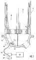
- FIG. 1 illustrates the tube tracking system of the invention.
- a mobile assembly 12 is placed anywhere at the bottom of the water box 10 of a steam generator 11, for example near a manhole 13. It is connected to a remote control unit 14 by an electrical link 15, itself connected to a control desk 17 comprising a display unit.
- a processing unit 16 is connected to this control unit.
- the camera 20 can use CCD or CID technology for its adaptation to the problems of digitization by image acquisition cards.
- the camera can be black and white or color. It has sufficient resolution to be scanned at 512 x 512 pixels.
- the signal / noise ratio is at least 48 DB to use all the dynamics of an 8-bit digitizer.
- a 12.5-75mm zoom has extreme aperture angles of 49 ° and 8 °.
- a hole placed at the end of the plate occupies about a tenth of the image in each dimension (for an average position of the camera: bottom of the water box, directly above the center of the plate).
- An autofocus device and an autoiris device are provided to permanently provide an image "in focus” and sufficiently clear, in particular during zoom variations. These devices can be disengageable.
- the lighting device preferably uses cold light (fluorescence).
- the light output can then be controlled by the control unit.
- the device for projecting a light index projects a light index, for example a flashing cross, onto the tube plate at the exact location displayed in the center of the image.
- This index allows operators to mark the hole designated by the means usually used (penetrant).
- the cross can then vary in flashing frequency and in brightness.
- the cross can be projected either by a device independent of the camera, or by the same device, for example, thanks to two laser spots deflected by semi-cylindrical prisms, which allows the axis of projection of the cross and to the optical axis of the camera to be confused.
- the two devices, camera and light index can be in the same housing or separate.
- the camera-mirror-lighting-cross unit light is installed in a closed, waterproof housing with a porthole.
- the shape of the box depends on where it should be positioned: in the case where it is placed in the bottom of the water box, it must allow a horizontal position of the camera. In this case, the box is arranged at the bottom of the water box so as to prevent any unwanted movement which could move it. This should allow the system to maintain the integrity of its benchmark and the integrity of the various parameters calculated during the calibration phase.
- the fixing can be done by a simple and easy to use system (suction cup, magnet, ...) which takes into account the surface conditions (boron deposit, stainless steel buttering, ). An attachment to the partition plate of the bowl can be envisaged.
- a single connecting cable can be used.
- a multiconductor cable or a monocoaxial cable with multiplexing can be used. This cable has good mechanical strength (anti-tearing system for the connector and the cable), with ease of plugging in and out of the connector.
- the video signal from the camera 20 arrives via the cable 15 on an image processing card.
- This image processing card is used to generate a fixed target centered on the optical axis of the vision system which is determined in the laboratory for the camera-lens pair used.
- the method used to determine the optical center uses four circles drawn on a plane that the vision system sees. For the two extreme focal lengths of the zoom, the center of the circles is determined. The intersection of the lines connecting the centers of the same circle for the extreme focal lengths, positions the optical center of the system. Knowing the coordinates of this point, the target can be generated by the map. The precision of this method is sufficient for the application: a method using image processing is also usable.
- the processing unit 16 performs the functions of controlling the motors, reading the positions of the encoders and of the control unit, digitizing and viewing the image, man-machine interface and calculating different position setpoints. .
- a good resolution monitor makes it possible to view, on a single screen, the images coming from the camera, the dialog menus, and possibly a virtual control panel.
- the processing unit 16 is for example composed of a PC type microcomputer.
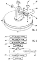
- the method of the invention after an initialization phase, ensures the automatic determination of the row and column numbers of the targeted holes, as a function of the angles of rotation of the camera. It can also do the reverse calculation, namely giving the registration system the angles with which it must rotate the camera automatically, to target a chosen hole.
- the position of the sealed housing relative to the plate is arbitrary and unknown. Initialization determines all the parameters necessary for proper operation.
- the center of a known tube is easily pointed and easily identifiable on the plate by the operator.
- four scores are sufficient (this is the minimum limit), but five give more precise results. Entering more points is also possible and further increases accuracy; but this additional precision is useless in normal use and it increases the input time by the operator and the calculation time.
- the row X and column Y numbers of the target point are entered by the operator.
- the angles of rotation in degrees, ⁇ and ⁇ of the camera, are read by the computer.
- the pairs of points are saved, then the operator starts the calculation of the parameters setting the shooting system in the environment of the steam generator for a fixed position. After a few seconds of calculation (on a PC 486-33 MHZ type computer for example) the parameters are displayed and are saved on hard drive. Exploitation can begin.
Landscapes
- Physics & Mathematics (AREA)
- General Physics & Mathematics (AREA)
- Monitoring And Testing Of Nuclear Reactors (AREA)
- Control Of Steam Boilers And Waste-Gas Boilers (AREA)
- Motor Or Generator Cooling System (AREA)
- Closed-Circuit Television Systems (AREA)
- Examining Or Testing Airtightness (AREA)
Applications Claiming Priority (2)
| Application Number | Priority Date | Filing Date | Title |
|---|---|---|---|
| FR9213155 | 1992-11-03 | ||
| FR9213155A FR2697632B1 (fr) | 1992-11-03 | 1992-11-03 | Système de repérage d'un tube dans une boîte à eau de générateur de vapeur et procédé de mise en Óoeuvre de ce système. |
Publications (2)
| Publication Number | Publication Date |
|---|---|
| EP0596793A1 true EP0596793A1 (de) | 1994-05-11 |
| EP0596793B1 EP0596793B1 (de) | 1997-04-02 |
Family
ID=9435133
Family Applications (1)
| Application Number | Title | Priority Date | Filing Date |
|---|---|---|---|
| EP93402688A Expired - Lifetime EP0596793B1 (de) | 1992-11-03 | 1993-11-02 | System zur Positionsidentifizierung einer Leitung in einem Wasserbehälter eines Dampferzeugers und Verfahren dazu |
Country Status (4)
| Country | Link |
|---|---|
| EP (1) | EP0596793B1 (de) |
| AT (1) | ATE151168T1 (de) |
| DE (1) | DE69309394T2 (de) |
| FR (1) | FR2697632B1 (de) |
Families Citing this family (2)
| Publication number | Priority date | Publication date | Assignee | Title |
|---|---|---|---|---|
| KR101502702B1 (ko) * | 2013-11-12 | 2015-03-13 | 한국원자력연구원 | 원자력 발전소 증기발생기 전열관 번호 확인 시스템 및 방법 |
| CN110812763A (zh) * | 2019-11-28 | 2020-02-21 | 广东为众消防科技股份有限公司 | 基于物联网监测的消防管道漏点自组网检测设备 |
Citations (4)
| Publication number | Priority date | Publication date | Assignee | Title |
|---|---|---|---|---|
| FR2409503A1 (fr) * | 1977-11-22 | 1979-06-15 | Electricite De France | Procede et dispositif de reperage d'un tube defectueux, notamment parmi le faisceau des tubes d'un generateur de vapeur |
| GB2097626A (en) * | 1981-04-29 | 1982-11-03 | Nuttall Edmund Ltd | Remote inspection and cutting equipment |
| EP0108587A2 (de) * | 1982-11-02 | 1984-05-16 | Ian Roland Yarnell | Fernsteuerbare Inspektionskameravorrichtung |
| JPS62144038A (ja) * | 1985-12-18 | 1987-06-27 | Power Reactor & Nuclear Fuel Dev Corp | 液体漏洩の遠隔検出,定量方法 |
-
1992
- 1992-11-03 FR FR9213155A patent/FR2697632B1/fr not_active Expired - Lifetime
-
1993
- 1993-11-02 EP EP93402688A patent/EP0596793B1/de not_active Expired - Lifetime
- 1993-11-02 AT AT93402688T patent/ATE151168T1/de not_active IP Right Cessation
- 1993-11-02 DE DE69309394T patent/DE69309394T2/de not_active Expired - Lifetime
Patent Citations (4)
| Publication number | Priority date | Publication date | Assignee | Title |
|---|---|---|---|---|
| FR2409503A1 (fr) * | 1977-11-22 | 1979-06-15 | Electricite De France | Procede et dispositif de reperage d'un tube defectueux, notamment parmi le faisceau des tubes d'un generateur de vapeur |
| GB2097626A (en) * | 1981-04-29 | 1982-11-03 | Nuttall Edmund Ltd | Remote inspection and cutting equipment |
| EP0108587A2 (de) * | 1982-11-02 | 1984-05-16 | Ian Roland Yarnell | Fernsteuerbare Inspektionskameravorrichtung |
| JPS62144038A (ja) * | 1985-12-18 | 1987-06-27 | Power Reactor & Nuclear Fuel Dev Corp | 液体漏洩の遠隔検出,定量方法 |
Non-Patent Citations (1)
| Title |
|---|
| PATENT ABSTRACTS OF JAPAN vol. 11, no. 373 (P - 643) 5 December 1987 (1987-12-05) * |
Also Published As
| Publication number | Publication date |
|---|---|
| FR2697632B1 (fr) | 1994-12-16 |
| ATE151168T1 (de) | 1997-04-15 |
| DE69309394D1 (de) | 1997-05-07 |
| FR2697632A1 (fr) | 1994-05-06 |
| DE69309394T2 (de) | 1997-10-23 |
| EP0596793B1 (de) | 1997-04-02 |
Similar Documents
| Publication | Publication Date | Title |
|---|---|---|
| US9778037B2 (en) | Scanner for space measurement | |
| JP4889913B2 (ja) | 赤外線に感応する赤外線カメラ | |
| JP5816778B2 (ja) | 追加の検出装置を備えたレーザスキャナ | |
| JP2953772B2 (ja) | 放射線源のリアルタイム位置測定装置 | |
| US5497188A (en) | Method for virtualizing an environment | |
| CN100368764C (zh) | 测量机 | |
| EP1024342A1 (de) | Automatische Vermessungsgerät und Verfahren zum dreidimensionalen Messen | |
| US9667890B2 (en) | Method for visualizing spatially-resolved measurement results and corresponding measuring arrangement | |
| JP5879431B2 (ja) | ロータブレードの診断 | |
| CN111263134A (zh) | 一种可定位的全景三维成像系统及定位方法 | |
| CN101501445B (zh) | 电子找平设备和方法 | |
| CN113376824A (zh) | 用于调整图像限制框的方法 | |
| CN1179830A (zh) | 目标探测装置 | |
| US7301617B2 (en) | Surveying apparatus | |
| EP0596793B1 (de) | System zur Positionsidentifizierung einer Leitung in einem Wasserbehälter eines Dampferzeugers und Verfahren dazu | |
| CN103973948A (zh) | 摄像设备 | |
| EP3407320B1 (de) | Hilfsverfahren zum einbau mindestens eines echten verdeckungselements für einen präsenzmelder, und entsprechende vorrichtung | |
| CN205426287U (zh) | 机器视觉料位计 | |
| CN114739637A (zh) | 一种舱外航天服头盔面窗光学性能综合测试装置及方法 | |
| CN105526993B (zh) | 机器视觉料位计及其测量料位的方法 | |
| JP5277600B2 (ja) | 架空線撮影システム及び方法 | |
| NL8105782A (nl) | Peilsysteem. | |
| Kibrick et al. | A comparison of exposure meter systems for three exoplanet-hunting spectrometers: Hamilton, HIRES and APF | |
| JP2747426B2 (ja) | 温度表示ビデオカメラ | |
| AU2014218432A1 (en) | An Inspection Device And System |
Legal Events
| Date | Code | Title | Description |
|---|---|---|---|
| PUAI | Public reference made under article 153(3) epc to a published international application that has entered the european phase |
Free format text: ORIGINAL CODE: 0009012 |
|
| AK | Designated contracting states |
Kind code of ref document: A1 Designated state(s): AT BE CH DE DK ES GB GR IE IT LI LU MC NL PT SE |
|
| 17P | Request for examination filed |
Effective date: 19941015 |
|
| 17Q | First examination report despatched |
Effective date: 19960209 |
|
| GRAG | Despatch of communication of intention to grant |
Free format text: ORIGINAL CODE: EPIDOS AGRA |
|
| GRAH | Despatch of communication of intention to grant a patent |
Free format text: ORIGINAL CODE: EPIDOS IGRA |
|
| GRAH | Despatch of communication of intention to grant a patent |
Free format text: ORIGINAL CODE: EPIDOS IGRA |
|
| GRAA | (expected) grant |
Free format text: ORIGINAL CODE: 0009210 |
|
| AK | Designated contracting states |
Kind code of ref document: B1 Designated state(s): AT BE CH DE DK ES GB GR IE IT LI LU MC NL PT SE |
|
| PG25 | Lapsed in a contracting state [announced via postgrant information from national office to epo] |
Ref country code: NL Effective date: 19970402 Ref country code: IT Free format text: LAPSE BECAUSE OF FAILURE TO SUBMIT A TRANSLATION OF THE DESCRIPTION OR TO PAY THE FEE WITHIN THE PRE;WARNING: LAPSES OF ITALIAN PATENTS WITH EFFECTIVE DATE BEFORE 2007 MAY HAVE OCCURRED AT ANY TIME BEFORE 2007. THE CORRECT EFFECTIVE DATE MAY BE DIFFERENT FROM THE ONE RECORDED.SCRIBED TIME-LIMIT Effective date: 19970402 Ref country code: GR Free format text: LAPSE BECAUSE OF FAILURE TO SUBMIT A TRANSLATION OF THE DESCRIPTION OR TO PAY THE FEE WITHIN THE PRESCRIBED TIME-LIMIT Effective date: 19970402 Ref country code: ES Free format text: THE PATENT HAS BEEN ANNULLED BY A DECISION OF A NATIONAL AUTHORITY Effective date: 19970402 Ref country code: DK Effective date: 19970402 Ref country code: AT Effective date: 19970402 |
|
| REF | Corresponds to: |
Ref document number: 151168 Country of ref document: AT Date of ref document: 19970415 Kind code of ref document: T |
|
| REG | Reference to a national code |
Ref country code: CH Ref legal event code: EP |
|
| REF | Corresponds to: |
Ref document number: 69309394 Country of ref document: DE Date of ref document: 19970507 |
|
| GBT | Gb: translation of ep patent filed (gb section 77(6)(a)/1977) |
Effective date: 19970610 |
|
| PG25 | Lapsed in a contracting state [announced via postgrant information from national office to epo] |
Ref country code: SE Effective date: 19970702 Ref country code: PT Effective date: 19970702 |
|
| REG | Reference to a national code |
Ref country code: IE Ref legal event code: FG4D Free format text: 72997 |
|
| NLV1 | Nl: lapsed or annulled due to failure to fulfill the requirements of art. 29p and 29m of the patents act | ||
| PG25 | Lapsed in a contracting state [announced via postgrant information from national office to epo] |
Ref country code: LU Free format text: LAPSE BECAUSE OF NON-PAYMENT OF DUE FEES Effective date: 19971102 |
|
| PG25 | Lapsed in a contracting state [announced via postgrant information from national office to epo] |
Ref country code: LI Free format text: LAPSE BECAUSE OF NON-PAYMENT OF DUE FEES Effective date: 19971130 Ref country code: CH Free format text: LAPSE BECAUSE OF NON-PAYMENT OF DUE FEES Effective date: 19971130 |
|
| PLBE | No opposition filed within time limit |
Free format text: ORIGINAL CODE: 0009261 |
|
| STAA | Information on the status of an ep patent application or granted ep patent |
Free format text: STATUS: NO OPPOSITION FILED WITHIN TIME LIMIT |
|
| 26N | No opposition filed | ||
| PG25 | Lapsed in a contracting state [announced via postgrant information from national office to epo] |
Ref country code: IE Free format text: LAPSE BECAUSE OF NON-PAYMENT OF DUE FEES Effective date: 19980330 |
|
| REG | Reference to a national code |
Ref country code: IE Ref legal event code: FD4D Ref document number: 72997 Country of ref document: IE |
|
| PG25 | Lapsed in a contracting state [announced via postgrant information from national office to epo] |
Ref country code: MC Free format text: LAPSE BECAUSE OF NON-PAYMENT OF DUE FEES Effective date: 19980531 |
|
| REG | Reference to a national code |
Ref country code: CH Ref legal event code: PL |
|
| REG | Reference to a national code |
Ref country code: GB Ref legal event code: IF02 |
|
| PGFP | Annual fee paid to national office [announced via postgrant information from national office to epo] |
Ref country code: DE Payment date: 20121113 Year of fee payment: 20 |
|
| PGFP | Annual fee paid to national office [announced via postgrant information from national office to epo] |
Ref country code: BE Payment date: 20121129 Year of fee payment: 20 Ref country code: GB Payment date: 20121127 Year of fee payment: 20 |
|
| REG | Reference to a national code |
Ref country code: DE Ref legal event code: R071 Ref document number: 69309394 Country of ref document: DE |
|
| REG | Reference to a national code |
Ref country code: GB Ref legal event code: PE20 Expiry date: 20131101 |
|
| BE20 | Be: patent expired |
Owner name: *ELECTRICITE DE FRANCE SERVICE NATIONAL Effective date: 20131102 |
|
| PG25 | Lapsed in a contracting state [announced via postgrant information from national office to epo] |
Ref country code: GB Free format text: LAPSE BECAUSE OF EXPIRATION OF PROTECTION Effective date: 20131101 Ref country code: DE Free format text: LAPSE BECAUSE OF EXPIRATION OF PROTECTION Effective date: 20131105 |