EP0596797B1 - Pied de robot marcheur - Google Patents
Pied de robot marcheur Download PDFInfo
- Publication number
- EP0596797B1 EP0596797B1 EP93402696A EP93402696A EP0596797B1 EP 0596797 B1 EP0596797 B1 EP 0596797B1 EP 93402696 A EP93402696 A EP 93402696A EP 93402696 A EP93402696 A EP 93402696A EP 0596797 B1 EP0596797 B1 EP 0596797B1
- Authority
- EP
- European Patent Office
- Prior art keywords
- fitting
- walking robot
- base plate
- foot according
- robot foot
- Prior art date
- Legal status (The legal status is an assumption and is not a legal conclusion. Google has not performed a legal analysis and makes no representation as to the accuracy of the status listed.)
- Expired - Lifetime
Links
- 230000006835 compression Effects 0.000 claims description 4
- 238000007906 compression Methods 0.000 claims description 4
- 230000001681 protective effect Effects 0.000 claims description 2
- 238000006073 displacement reaction Methods 0.000 description 5
- 229920001296 polysiloxane Polymers 0.000 description 3
- 229910052782 aluminium Inorganic materials 0.000 description 1
- XAGFODPZIPBFFR-UHFFFAOYSA-N aluminium Chemical compound [Al] XAGFODPZIPBFFR-UHFFFAOYSA-N 0.000 description 1
- 238000009412 basement excavation Methods 0.000 description 1
- 238000013016 damping Methods 0.000 description 1
- 239000013013 elastic material Substances 0.000 description 1
- 231100001261 hazardous Toxicity 0.000 description 1
- 230000001939 inductive effect Effects 0.000 description 1
- 238000009434 installation Methods 0.000 description 1
- 230000005291 magnetic effect Effects 0.000 description 1
- 239000000463 material Substances 0.000 description 1
- 230000007246 mechanism Effects 0.000 description 1
- 229910052751 metal Inorganic materials 0.000 description 1
- 239000002184 metal Substances 0.000 description 1
- 238000000034 method Methods 0.000 description 1
- 230000003287 optical effect Effects 0.000 description 1
- 230000002787 reinforcement Effects 0.000 description 1
- 238000007789 sealing Methods 0.000 description 1
- 125000000391 vinyl group Chemical group [H]C([*])=C([H])[H] 0.000 description 1
- 229920002554 vinyl polymer Polymers 0.000 description 1
Images
Classifications
-
- B—PERFORMING OPERATIONS; TRANSPORTING
- B62—LAND VEHICLES FOR TRAVELLING OTHERWISE THAN ON RAILS
- B62D—MOTOR VEHICLES; TRAILERS
- B62D57/00—Vehicles characterised by having other propulsion or other ground- engaging means than wheels or endless track, alone or in addition to wheels or endless track
- B62D57/02—Vehicles characterised by having other propulsion or other ground- engaging means than wheels or endless track, alone or in addition to wheels or endless track with ground-engaging propulsion means, e.g. walking members
- B62D57/032—Vehicles characterised by having other propulsion or other ground- engaging means than wheels or endless track, alone or in addition to wheels or endless track with ground-engaging propulsion means, e.g. walking members with alternately or sequentially lifted supporting base and legs; with alternately or sequentially lifted feet or skid
-
- B—PERFORMING OPERATIONS; TRANSPORTING
- B62—LAND VEHICLES FOR TRAVELLING OTHERWISE THAN ON RAILS
- B62D—MOTOR VEHICLES; TRAILERS
- B62D57/00—Vehicles characterised by having other propulsion or other ground- engaging means than wheels or endless track, alone or in addition to wheels or endless track
- B62D57/02—Vehicles characterised by having other propulsion or other ground- engaging means than wheels or endless track, alone or in addition to wheels or endless track with ground-engaging propulsion means, e.g. walking members
Definitions
- the invention relates to a walking robot foot.
- Some mobile robots progress on the ground like many living beings, leaning on legs that perform alternating movements back and forth during which feet are alternately placed on the ground and raised.
- the traditional sensors used to recognize the robot's environment by an artificial vision or a similar process have difficulty distinguishing certain categories of obstacles or obstructions, in particular unevennesses like stair steps, certain small objects placed on the ground and surfaces such as gratings. They are more complicated and costly to implement, and they can be easily altered, for example by fouling. They are therefore not reliable in many circumstances and in particular if the robot has to make long journeys among industrial installations.
- the walking robot foot comprises a frame provided with a sole support plane on the ground, a universal joint between the armature and another part of the robot and which is designed to allow orientations of the sole in all directions, sensors of inclination of the sole, sensors of ground contact located next to the sole and substantially in the plane of the sole, the reinforcement being designed in two parts, characterized in that the two parts are connected by a spring for absorbing the compression energy of the foot produced by the other part of the robot, one of the parts of the armature carrying the universal joint and the other of the parts of the armature carrying the sole and the contact sensors.
- the robot foot according to the preamble of claim 1 is known from EP-A-0406018.
- the contact sensors are advantageously retractable pads and connected to the frame by springs. Detecting their movement unambiguously identifies the contact.
- the frame can be completed by a lateral border which surrounds the sole and which is movable to deform as soon as it touches an obstacle lateral, which indicates that it is preferable to move the foot away.
- the foot is connected to the lower end of a leg 1 of the robot, not shown elsewhere but which may be similar to that of French patent 2 653 516, by a universal joint 2, composed of a movable cage 3 of which come out a transverse axis 4 fixed to the leg 1 and a longitudinal axis 5 fixed to the top of a frame 6 of the foot.
- the shafts 4 and 5 are hollow and each house an angular sensor 7 or 8 which makes it possible to measure their rotation.
- the sensors 7 and 8 are, like the others which will be described soon, connected to the robot control system by wires 9 which run along the leg 1.
- leg 1 If the leg 1 is moved without its inclination ever varying, it is possible to immediately know the inclination of the foot and above all of a flat and horizontal sole 10 supporting the ground, which belongs to it and which is fixed to the underside of a lower part 11 of the frame 6. Otherwise, the the inclination of the sole 10 can be calculated by knowing the inclination of the leg 1.
- Vertical guide posts 12 rise from the top surface of this lower part 11 and pass through bores made in an upper part 13 of the frame 6, which carries the universal joint 2, and allow the part upper 13 to slide vertically relative to the other.
- a spring 14 is housed in an excavation 15 between the parts 11 and 13 of the frame 6: when the leg 1 is lowered, it is compressed as soon as the sole 10 touches the ground until it transmits all of the weight of the robot that hangs over the foot.
- the spring 14 is not a conventional metal spring but a system consisting of a circular rubber band 35 glued to the lower part 11, and a silicone hose 36 curled in a loop and crushed between the rubber band 35 and the upper part 13, to which it is bonded: the silicone tube 36 is ovalized with a low and uniform stiffness when it is compressed, and until it is completely crushed, after which the spring 14 has only the elasticity of great stiffness of the rubber band 35; the system is first flexible enough to allow the foot to be placed well before the total application of the effort, in order to be able to anticipate incorrect or hazardous support, then rigid enough to no longer produce significant compression when the effort begins to be applied.
- the silicone hose 36 also has the great advantage of straightening without producing significant vibrations when it is released, that is to say that it has a high damping. Finally, the undesirable horizontal translation movements of the two parts 11 and 13 of the frame 6 are more or less prohibited, since the spring 14 is very rigid with respect to these movements.
- the upper part 13 of the frame 6 comprises a pivot part 16 carrying the universal joint 2, connected to the rest by a bearing 17 rotating around a vertical axis and which thus allows the sole 10 to rotate while remaining in a invariable plane determined by the movements of the universal joint 2. It is then useful to provide the pivot 16 with stops 18 which come to touch some of the balusters 12 to limit rotation and not tearing off sensor wires or damaging the sleeve 19 advantageously used to wrap most of the foot, with the exception of its lower surface.
- the upper edge of the sleeve 19 is crimped around the leg 1: it is made of elastic material and therefore twists as soon as a pivoting of the sole 10 is produced, but it brings the foot back into a privileged position when the foot is raised. It is also useful for protecting the mechanisms of the foot from impact and dirt. To relieve the lower part of the sleeve 19, an additional crimp is made at the top of the frame 6, on a circular surface 37.
- the lower part 11 of the frame 6 comprises a border 20 around the upper part 13 and which carries a ring 21, whether continuous or not, which surrounds it, as well as the sole 10, and which the sleeve 19 insulates from the outside. .
- the ring 21 is mounted on the edge 20 by means of a spring 22 which can here again be a flexible hose wound around the edge 20.
- the ring 21 is moreover freely movable around the edge 20: it it is preferable that its friction on the spring 22 is reduced, which is the case if it is made of aluminum and the spring 22 is made of vinyl.
- Displacement sensors 23 are arranged in a crown on the edge 20 and measure the displacements of the ring 21 which occur as soon as it touches lateral obstacles, which are thus signaled to the robot control system.
- Other displacement sensors 24 are inserted in the lower part 11, in front of contact sensors 25 essentially consisting of a pad 26 mounted on an elastic blade 27, the opposite end of which is embedded in the lower part 11.
- the pads 26 are finished with a shoe 28 which extends a little below the sole 10 and must generally touch the ground when the latter is placed on it. The shoe 28 and the pad 26 are then pushed back, and the blade 27 is bent. These movements are identified by the displacement sensors 24 and reported to the robot control system.
- the pads 26 are arranged next to the sole 10, that is to say around it or possibly in gaps therein. The support of the foot on the ground is interrupted by the control system and the foot is moved if too few of these sensors are moved, because this generally means that the sole 10 only touches the ground on too small an area, or even an object placed on the ground.
- the pads 26 and the blades 27 are housed in cells 29 of the lower part 11, which are advantageously covered by a flexible protective sheet 30 ensuring in particular sealing, possibly common to all cells 29 and therefore extending over almost the entire lower surface of the frame 6. It then has a portion covered by the sole 10, which clamps it against the lower part 11 by fixing screws 31. Similarly, portions of the flexible sheet 30 are tightened between the pads 26 and the pads 28 by fixing screws 32 of the pads 28 which allow the pads 28 to be replaced at will when they are worn.
- Screws 33, rivets or any other means can be used to fix the flexible sheet 30 and the sleeve 19 to the frame.
- the periphery of the cells 29 is advantageously provided with a rounded rim which does not risk cutting the flexible sheet 30 when the pads 26 are retracted.
- the foot described here therefore offers all the guarantees of safety, and it can be used for almost all kinds of floors.
- the displacement sensors 23 and 24 can be inductive, optical, magnetic or other, or even consist of potentiometers or micro-precision switches, that is to say with or without material contact.
Landscapes
- Engineering & Computer Science (AREA)
- Chemical & Material Sciences (AREA)
- Combustion & Propulsion (AREA)
- Transportation (AREA)
- Mechanical Engineering (AREA)
- Manipulator (AREA)
- Toys (AREA)
Description
- L'invention a trait à un pied de robot marcheur.
- Certains robots mobiles progressent sur le sol à la manière de nombreux êtres vivants, en s'appuyant sur des pattes qui effectuent des mouvements alternés en avant et en arrière pendant lesquels des pieds sont alternativement posés sur le sol et soulevés.
- Un problème important de cette catégorie de robots est que la qualité de l'appui du pied au sol est souvent imprévisible, ce qui peut provoquer le déséquilibre et la chute du robot si par exemple le pied glisse sur une surface trop inclinée ou un objet mobile posé sur le sol, si le contact est produit sur une trop faible superficie qui s'effondre dès que le poids du robot est appliqué, ou si l'appui n'existe que sur une partie excentrée du pied, qui bascule ensuite.
- Les capteurs traditionnels utilisés pour reconnaêtre l'environnement du robot par une vision artificielle ou un procédé du même genre ont du mal à distinguer certaines catégories d'obstacles ou d'embêches, notamment des dénivellations comme les marches d'escalier, certains petits objets posés sur le sol et les surfaces telles que les caillebotis. Ils sont de plus compliqués et coêteux à mettre en oeuvre, et ils peuvent être facilement altérés, par exemple en s'encrassant. Ils ne sont donc pas fiables dans de nombreuses circontances et notamment si le robot doit accomplir de longs trajets parmi les installations industrielles.
- Le pied de robot marcheur conforme à l'invention comprend une armature munie d'une semelle plane d'appui sur le sol, un joint de cardan entre l'armature et une autre partie du robot et qui est conçue pour autoriser des orientations de la semelle dans toutes les directions, des capteurs d'inclinaison de la semelle, des capteurs de contact du sol situés à côté de la semelle et sensiblement dans le plan de la semelle, l'armature étant conçue en deux parties, caractérisé en ce que les deux parties sont reliées par un ressort d'absorption d'énergie de compression du pied produite par l'autre partie du robot, l'une des parties de l'armature portant le joint de cardan et l'autre des parties de l'armature portant la semelle et les capteurs de contact. Le pied de robot selon le préambule de la revendication 1 est connu de EP-A-0406018.
- La combinaison de ces moyens permet en effet de remédier aux inconvénients mentionnés plus haut : la semelle se place d'elle-même à l'orientation locale du sol, mais les capteurs d'inclinaison peuvent refuser l'appui si l'inclinaison est trop forte pour exclure un glissement ; le capteur de contact permet de vérifier si l'appui est produit sur une surface suffisante et donc suffisamment ferme ; enfin, la division de l'armature en deux parties reliées par des ressorts permet de ne pas appliquer immédiatement l'intégralité de l'effort d'appui, ce qui laisse le temps nécessaire pour vérifier la qualité de l'appui et éventuellement relever le pied pour tenter de le poser ailleurs.
- Les capteurs de contact sont avantageusement des coussinets rétractiles et reliés à l'armature par des ressorts. La détection de leur déplacement permet d'identifier sans ambiguïté le contact.
- L'armature peut être complétée par une bordure latérale qui entoure la semelle et qui est mobile pour se déformer dès qu'elle touche un obstacle latéral, ce qui indique qu'il est préférable d'éloigner le pied.
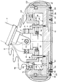
- On va maintenant décrire plus en détail l'invention à l'aide de la figure unique qui illustre une vue en coupe longitudinale d'un pied conforme à l'invention.
- Le pied est relié à l'extrémité inférieure d'une jambe 1 du robot, non représenté par ailleurs mais qui peut être semblable à celui du brevet français 2 653 516, par un joint de cardan 2, composé d'une cage 3 mobile dont sortent un axe transversal 4 fixé à la jambe 1 et un axe longitudinal 5 fixé au sommet d'une armature 6 du pied. Les arbres 4 et 5 sont creux et abritent chacun un capteur angulaire 7 ou 8 qui permet de mesurer leur rotation. Les capteurs 7 et 8 sont, comme les autres qui seront bientêt décrits, reliés au système de commande du robot par des fils 9 qui courent le long de la jambe 1. Si la jambe 1 est déplacée sans que son inclinaison varie jamais, on peut connaêtre immédiatement l'inclinaison du pied et surtout d'une semelle 10 plane et horizontale d'appui au sol, qui lui appartient et qui est fixée à la surface de dessous d'une partie inférieure 11 de l'armature 6. Sinon, l'inclinaison de la semelle 10 peut être calculée en connaissant l'inclinaison de la jambe 1.
- Des colonnettes 12 verticales de guidage s'élèvent de la surface de dessus de cette partie inférieure 11 et passent à travers des perçages ménagés dans une partie supérieure 13 de l'armature 6, qui porte le joint de cardan 2, et permettent à la partie supérieure 13 de coulisser verticalement par rapport à l'autre. Un ressort 14 est logé dans une excavation 15 entre les parties 11 et 13 de l'armature 6 : quand la jambe 1 s'abaisse, il est comprimé dès que la semelle 10 touche le sol jusqu'à ce qu'il transmette toute la partie du poids du robot qui pèse sur le pied.
- Le ressort 14 n'est pas un ressort métallique classique mais un système constitué d'une bande de caoutchouc 35 circulaire collée sur la partie inférieure 11, et d'un tuyau de silicone 36 recourbé en boucle et écrasé entre la bande de caoutchouc 35 et la partie supérieure 13, auxquelles il est collé : le tuyau de silicone 36 s'ovalise avec une raideur faible et uniforme quand il est comprimé, et jusqu'à ce qu'il soit totalement écrasé, après quoi le ressort 14 ne possède plus que l'élasticité de grande raideur de la bande de caoutchouc 35 ; le système est d'abord suffisamment souple pour permettre de poser le pied bien avant l'application totale de l'effort, afin de pouvoir anticiper les appuis incorrects ou hasardeux, puis suffisamment rigide pour ne plus produire de compression importante quand l'effort commence à être appliqué. Le tuyau de silicone 36 a de plus le grand avantage de se redresser sans produire de vibrations importantes quand il est relêché, c'est-à- dire qu'il a un fort amortissement. Enfin, les mouvements de translation horizontale, indésirables, des deux parties 11 et 13 de l'armature 6 sont à peu près interdits, car le ressort 14 est très rigide vis-à-vis de ces mouvements.
- La partie supérieure 13 de l'armature 6 comporte une partie de pivot 16 porteuse du joint de cardan 2, reliée au reste par un roulement 17 rotatif autour d'un axe vertical et qui autorise ainsi la semelle 10 à tourner tout en restant dans un plan invariable que les mouvements du joint de cardan 2 ont déterminé. Il est alors utile de munir le pivot 16 de butées 18 qui viennent toucher certaines des colonnettes 12 pour limiter la rotation et ne pas arracher des fils de capteurs ni détériorer le manchon 19 avantageusement employé pour envelopper la plus grande partie du pied, à l'exception de sa surface inférieure. Le bord supérieur du manchon 19 est serti autour de la jambe 1 : il est en matériau élastique et se tord donc dès qu'un pivotement de la semelle 10 est produit, mais il ramène le pied dans une position privilégiée quand le pied est soulevé. Il est par ailleurs utile pour protéger les mécanismes du pied des chocs et des salissures. Pour soulager la partie inférieure du manchon 19, une sertissure supplémentaire est réalisée au sommet de l'armature 6, sur une portée circulaire 37.
- La partie inférieure 11 de l'armature 6 comprend une bordure 20 autour de la partie supérieure 13 et qui porte un anneau 21, continu ou non qui l'entoure, ainsi que la semelle 10, et que le manchon 19 isole de l'extérieur. L'anneau 21 est monté sur la bordure 20 par l'intermédiaire d'un ressort 22 qui peut être ici encore un tuyau souple enroulé autour de la bordure 20. L'anneau 21 est par ailleurs librement mobile autour de la bordure 20 : il est préférable que ses frottements sur le ressort 22 soient réduits, ce qui est le cas s'il est en aluminium et que le ressort 22 est en vinyle. Des capteurs 23 de déplacement sont disposés en couronne sur la bordure 20 et mesurent les déplacements de l'anneau 21 qui se produisent dès qu'il touche des obstacles latéraux, qui sont ainsi signalés au système de commande du robot.
- D'autres capteurs de déplacement 24 sont insérés dans la partie inférieure 11, devant des capteurs de contact 25 constitués essentiellement d'un coussinet 26 monté sur une lame élastique 27 dont l'extrémité opposée est encastrée dans la partie inférieure 11. Les coussinets 26 sont terminés par un patin 28 qui s'étend un peu au-dessous de la semelle 10 et doit généralement toucher le sol quand celle-ci est posée sur lui. Le patin 28 et le coussinet 26 sont alors repoussés, et la lame 27 est fléchie. Ces déplacements sont repérés par les capteurs de déplacement 24 et rapportés au système de commande du robot. Les coussinets 26 sont disposés à cêté de la semelle 10, c'est-à-dire autour d'elle ou éventuellement dans des lacunes de celle-ci. L'appui du pied au sol est interrompu par le système de commande et le pied est déplacé si trop peu de ces capteurs sont déplacés, car cela signifie généralement que la semelle 10 ne touche le sol que sur une trop petite superficie, voire un objet posé sur le sol.
- Les coussinets 26 et les lames 27 sont logés dans des alvéoles 29 de la partie inférieure 11, qui sont avantageusement recouverts par une feuille souple 30 de protection assurant notamment l'étanchéité, éventuellement commune à tous les alvéoles 29 et s'étendant donc sur presque toute la surface inférieure de l'armature 6. Elle comporte alors une portion recouverte par la semelle 10, qui la serre contre la partie inférieure 11 par des vis de fixation 31. De façon analogue, des portions de la feuille souple 30 sont serrées entre les coussinets 26 et les patins 28 par des vis de fixation 32 des patins 28 qui permettent de remplacer à volonté les patins 28 quand ils sont usés.
- Des vis 33, des rivets ou n'importe quel autre moyen peuvent être utilisés pour fixer la feuille souple 30 et le manchon 19 à l'armature.
- Le pourtour des alvéoles 29 est avantageusement muni d'un rebord arrondi qui ne risque pas de couper la feuille souple 30 quand les coussinets 26 sont rétractés.
- Le pied décrit ici offre donc toutes les garanties de sécurité, et il est utilisable pour à peu près tous les genres de sols.
- Les capteurs 23 et 24 de déplacement peuvent être inductifs, optiques, magnétiques ou autres, ou encore constitués de potentiomètres ou de micro-rupteurs de précision, c'est-à-dire avec ou sans contact matériel.
Claims (10)
- Pied de robot marcheur comprenant une armature (6) munie d'une semelle plane (10) d'appui sur le sol, un joint de cardan (2) entre l'armature (6) et une autre partie (1) du robot et qui est conçu pour autoriser des orientations de la semelle (10) dans toutes les directions, des capteurs (7, 8) d'inclinaison de la semelle (10), des capteurs de contact (25) du sol situés à côté de la semelle (10) et sensiblement dans le plan de la semelle, l'armature étant conçue en deux parties (11, 13), caractérisé en ce que les deux parties sont reliées par un ressort (14) d'absorption d'énergie de compression du pied produite par l'autre partie du robot, l'une des parties (13) de l'armature portant le joint de cardan (2) et l'autre des parties (11) de l'armature portant la semelle (10) et les capteurs de contact (25).
- Pied de robot marcheur suivant la revendication 1, caractérisé en ce que les deux parties de l'armature sont reliées par des colonnettes (12) de guidage coulissant.
- Pied de robot marcheur suivant l'une quelconque des revendications 1 ou 2, caractérisé en ce que le ressort (14) a une rigidité d'ensemble croissant avec la compression du pied.
- Pied de robot marcheur suivant l'une quelconque des revendications 1 à 3, caractérisé en ce que les capteurs de contact (25) sont des coussinets (26) rétractiles reliés à l'armature (6) par des ressorts (27).
- Pied de robot marcheur suivant la revendication 4, caractérisé en ce que les coussinets (26) sont mobiles dans des alvéoles (29) de l'armature (6), les alvéoles (29) étant recouverts d'une feuille souple (30) de protection.
- Pied de robot marcheur suivant la revendication 5, caractérisé en ce que la feuille souple (30) est commune à tous les alvéoles (29), la semelle (10) étant montée sur l'armature (6) en recouvrant une portion de la feuille souple (30).
- Pied de robot marcheur suivant l'une quelconque des revendications 4 à 6, caractérisé en ce que les coussinets (26) sont munis de patins (28) remplaçables destinés à toucher le sol.
- Pied de robot marcheur suivant l'une quelconque des revendications 1 à 7, caractérisé en ce que l'armature (6) comprend une bordure latérale mobile (21), entourant la semelle (10), de contact à des obstacles.
- Pied de robot marcheur suivant l'une quelconque des revendications 1 à 8, caractérisé en ce que l'armature (6) comprend un pivot (17) autorisant des rotations de la semelle (10) dans le plan de la semelle, ainsi qu'un moyen (19) de rappel du pivot à un état privilégié.
- Pied de robot marcheur suivant la revendication 9, caractérisé en ce que le moyen de rappel est un manchon qui enveloppe le pied, hormis la semelle et les capteurs de contact.
Applications Claiming Priority (2)
| Application Number | Priority Date | Filing Date | Title |
|---|---|---|---|
| FR9213326A FR2697492B1 (fr) | 1992-11-05 | 1992-11-05 | Pied de robot marcheur. |
| FR9213326 | 1992-11-05 |
Publications (2)
| Publication Number | Publication Date |
|---|---|
| EP0596797A1 EP0596797A1 (fr) | 1994-05-11 |
| EP0596797B1 true EP0596797B1 (fr) | 1996-03-13 |
Family
ID=9435258
Family Applications (1)
| Application Number | Title | Priority Date | Filing Date |
|---|---|---|---|
| EP93402696A Expired - Lifetime EP0596797B1 (fr) | 1992-11-05 | 1993-11-03 | Pied de robot marcheur |
Country Status (6)
| Country | Link |
|---|---|
| US (1) | US5421426A (fr) |
| EP (1) | EP0596797B1 (fr) |
| JP (1) | JPH06198582A (fr) |
| DE (1) | DE69301807T2 (fr) |
| ES (1) | ES2086907T3 (fr) |
| FR (1) | FR2697492B1 (fr) |
Families Citing this family (28)
| Publication number | Priority date | Publication date | Assignee | Title |
|---|---|---|---|---|
| JP3330710B2 (ja) * | 1993-12-30 | 2002-09-30 | 本田技研工業株式会社 | 移動ロボットの位置検知および制御装置 |
| US5758734A (en) * | 1996-01-19 | 1998-06-02 | Korea Institute Of Science And Technology | Foot system for jointed leg type walking robot |
| DE69943312D1 (de) | 1998-06-09 | 2011-05-12 | Sony Corp | Manipulator und verfahren zur steuerung seiner lage |
| JP2001239479A (ja) * | 1999-12-24 | 2001-09-04 | Sony Corp | 脚式移動ロボット及びロボットのための外装モジュール |
| US6443993B1 (en) * | 2001-03-23 | 2002-09-03 | Wayne Koniuk | Self-adjusting prosthetic ankle apparatus |
| JP4733317B2 (ja) * | 2001-08-28 | 2011-07-27 | 本田技研工業株式会社 | 脚式歩行ロボットの床反力検出器 |
| JP3598507B2 (ja) * | 2002-06-12 | 2004-12-08 | 独立行政法人 科学技術振興機構 | 歩行式移動装置及びその歩行制御装置及び歩行制御方法 |
| KR100541433B1 (ko) * | 2002-12-23 | 2006-01-11 | 삼성전자주식회사 | 2족보행로봇 |
| KR100499143B1 (ko) * | 2003-02-27 | 2005-07-04 | 삼성전자주식회사 | 보행 로봇의 지면 반력 측정 모듈 및 이를 장착한 로봇 발구조물 |
| JP4495549B2 (ja) * | 2004-08-30 | 2010-07-07 | 本田技研工業株式会社 | 脚式移動ロボット |
| CN1294045C (zh) * | 2004-09-09 | 2007-01-10 | 上海交通大学 | 足部浮动支撑的四足步行机器人的脚结构 |
| CN102180206B (zh) * | 2011-04-24 | 2012-07-04 | 杭州电子科技大学 | 一种具有柔性关节的机器人脚部机构 |
| KR20130073591A (ko) * | 2011-12-23 | 2013-07-03 | 삼성전자주식회사 | 지지모듈 및 이를 포함하는 로봇 |
| CN102602464A (zh) * | 2012-03-08 | 2012-07-25 | 东南大学 | 带有阻尼减震轮的小型履带侦察机器人 |
| US9183346B2 (en) | 2012-03-12 | 2015-11-10 | Empire Technology Development Llc | Robotic appendages |
| CN103204191B (zh) * | 2013-03-11 | 2015-10-14 | 大连理工大学 | 一种机器人的足端机构 |
| CN103434581B (zh) * | 2013-08-08 | 2015-10-14 | 大连理工大学 | 一种机器人的脚掌机构 |
| CN104627264B (zh) * | 2014-12-04 | 2017-01-25 | 河海大学常州校区 | 柔性仿生机器人脚 |
| US9994269B1 (en) | 2015-11-12 | 2018-06-12 | Schaft Inc. | Rotatable extension for robot foot |
| US9821866B1 (en) | 2015-11-12 | 2017-11-21 | Schaft Inc. | Rotatable robot foot with perpendicular soles |
| CN107284550B (zh) * | 2017-06-09 | 2020-04-14 | 北京航空航天大学 | 一种重载轻质弹性机械足 |
| CN107320182B (zh) * | 2017-07-31 | 2021-03-30 | 成都博恩思医学机器人有限公司 | 用于手术台车底座的驱动轮组件及手术台车底座 |
| WO2019041074A1 (fr) * | 2017-08-27 | 2019-03-07 | 刘哲 | Dispositif de pied de robot marcheur présentant une forte capacité de tenue de route |
| CN109969285B (zh) * | 2019-03-07 | 2021-03-30 | 哈尔滨工业大学 | 机器人用流体万向柔顺与力传感掌 |
| CN111098949B (zh) * | 2019-12-18 | 2021-05-28 | 南京涵曦月自动化科技有限公司 | 一种足式机器人的腿足弹性装置 |
| CN112298397B (zh) * | 2020-11-03 | 2022-06-10 | 武汉理工大学 | 一种适用于全地形路况的轮步式机器人足端机构 |
| CN113511284B (zh) * | 2021-07-30 | 2022-08-23 | 中国空空导弹研究院 | 一种四足机器人的足部结构 |
| CN115285252B (zh) * | 2022-08-30 | 2023-04-25 | 内蒙古第一机械集团股份有限公司 | 一种足式行走机器人十字万向节足部机构 |
Family Cites Families (6)
| Publication number | Priority date | Publication date | Assignee | Title |
|---|---|---|---|---|
| FR379528A (fr) * | 1907-07-04 | 1907-11-09 | Henry Selby Hele Shaw | Système de propulsion des véhicules de transport sur terre |
| JP2520019B2 (ja) * | 1989-06-29 | 1996-07-31 | 本田技研工業株式会社 | 脚式移動ロボットの駆動制御装置 |
| US5219410A (en) * | 1989-10-20 | 1993-06-15 | Commissariat A L'energie Atomique | Device for transmitting movement between a solid and a member, in particular for a robot able to be moved on legs |
| FR2653516B1 (fr) * | 1989-10-20 | 1994-12-23 | Commissariat Energie Atomique | Transmission deformable a barres articulees et vehicule equipe de telles transmissions. |
| US5255753A (en) * | 1989-12-14 | 1993-10-26 | Honda Giken Kogyo Kabushiki Kaisha | Foot structure for legged walking robot |
| JP2826858B2 (ja) * | 1989-12-14 | 1998-11-18 | 本田技研工業株式会社 | 脚式歩行ロボットの足部構造 |
-
1992
- 1992-11-05 FR FR9213326A patent/FR2697492B1/fr not_active Expired - Fee Related
-
1993
- 1993-10-18 US US08/138,915 patent/US5421426A/en not_active Expired - Fee Related
- 1993-11-03 EP EP93402696A patent/EP0596797B1/fr not_active Expired - Lifetime
- 1993-11-03 ES ES93402696T patent/ES2086907T3/es not_active Expired - Lifetime
- 1993-11-03 DE DE69301807T patent/DE69301807T2/de not_active Expired - Fee Related
- 1993-11-04 JP JP5275750A patent/JPH06198582A/ja not_active Withdrawn
Also Published As
| Publication number | Publication date |
|---|---|
| US5421426A (en) | 1995-06-06 |
| FR2697492A1 (fr) | 1994-05-06 |
| EP0596797A1 (fr) | 1994-05-11 |
| JPH06198582A (ja) | 1994-07-19 |
| DE69301807T2 (de) | 1996-10-02 |
| FR2697492B1 (fr) | 1994-12-23 |
| ES2086907T3 (es) | 1996-07-01 |
| DE69301807D1 (de) | 1996-04-18 |
Similar Documents
| Publication | Publication Date | Title |
|---|---|---|
| EP0596797B1 (fr) | Pied de robot marcheur | |
| EP0552994B1 (fr) | Chaussure, en particulier chaussure de sport, comportant au moins un ressort disposé dans la semelle, cassette et ressort pour une telle chaussure | |
| EP3152013B1 (fr) | Système anti coincement dans un robot à caractère humanoïde | |
| FR2543097A1 (fr) | Frein hydraulique a commande manuelle pour bicyclette et procede de freinage | |
| EP3595593B1 (fr) | Prothèse de pied comportant un élément d'amortissement | |
| EP1838397A1 (fr) | Installation autonome pour la course, apte a etre repliee sous encombrement reduit | |
| EP2164443A1 (fr) | Procede et appareil de massage | |
| EP3231399A1 (fr) | Genou prothetique pour un patient ampute femoral | |
| EP0363241A1 (fr) | Barrière de parking en forme d'un arceau pivotant entre des positions relevée et abaissée | |
| WO2017085014A1 (fr) | Robot a caractere humanoïde motorise | |
| EP1565081B1 (fr) | Ensemble comprenant deux bottes articulees ayant des caracteristiques mecaniques differentes | |
| FR2512682A1 (fr) | Frein pour ski | |
| EP1961463A1 (fr) | Raquette à neige perfectionnée | |
| EP0631852B1 (fr) | Dispositif de pose d'un joint d'étanchéité | |
| EP1515623B1 (fr) | Botte a articulation flottante | |
| FR2714270A1 (fr) | Chausure de ski à capot avant suspendu. | |
| FR2544969A1 (fr) | Chaussure de ski | |
| FR2749183A1 (fr) | Patin a roues en ligne amorti | |
| FR3111791A1 (fr) | Dispositif d’assistance a l’articulation pied/cheville | |
| EP1792758A1 (fr) | Dispositif formant butée de détente d'une suspension d'un véhicule notamment automobile | |
| EP3623230A1 (fr) | Véhicule doté d'un airbag rideau amélioré | |
| FR2711043A1 (fr) | Chaussure de ski alpin. | |
| EP1808384B1 (fr) | Dispositif de marchepied, et véhicule équipé d'un tel dispositif | |
| FR2754511A1 (fr) | Vehicules sur roues pour monter et descendre des escaliers mecaniques | |
| WO2011128588A1 (fr) | Orthèse dynamique de type releveur de pied |
Legal Events
| Date | Code | Title | Description |
|---|---|---|---|
| PUAI | Public reference made under article 153(3) epc to a published international application that has entered the european phase |
Free format text: ORIGINAL CODE: 0009012 |
|
| AK | Designated contracting states |
Kind code of ref document: A1 Designated state(s): BE DE ES GB IT |
|
| 17P | Request for examination filed |
Effective date: 19941015 |
|
| 17Q | First examination report despatched |
Effective date: 19940606 |
|
| GRAA | (expected) grant |
Free format text: ORIGINAL CODE: 0009210 |
|
| AK | Designated contracting states |
Kind code of ref document: B1 Designated state(s): BE DE ES GB IT |
|
| REF | Corresponds to: |
Ref document number: 69301807 Country of ref document: DE Date of ref document: 19960418 |
|
| ITF | It: translation for a ep patent filed | ||
| GBT | Gb: translation of ep patent filed (gb section 77(6)(a)/1977) |
Effective date: 19960521 |
|
| REG | Reference to a national code |
Ref country code: ES Ref legal event code: FG2A Ref document number: 2086907 Country of ref document: ES Kind code of ref document: T3 |
|
| PLBE | No opposition filed within time limit |
Free format text: ORIGINAL CODE: 0009261 |
|
| STAA | Information on the status of an ep patent application or granted ep patent |
Free format text: STATUS: NO OPPOSITION FILED WITHIN TIME LIMIT |
|
| 26N | No opposition filed | ||
| PGFP | Annual fee paid to national office [announced via postgrant information from national office to epo] |
Ref country code: GB Payment date: 20001101 Year of fee payment: 8 |
|
| PGFP | Annual fee paid to national office [announced via postgrant information from national office to epo] |
Ref country code: BE Payment date: 20001109 Year of fee payment: 8 |
|
| PGFP | Annual fee paid to national office [announced via postgrant information from national office to epo] |
Ref country code: ES Payment date: 20001124 Year of fee payment: 8 |
|
| PGFP | Annual fee paid to national office [announced via postgrant information from national office to epo] |
Ref country code: DE Payment date: 20001129 Year of fee payment: 8 |
|
| PG25 | Lapsed in a contracting state [announced via postgrant information from national office to epo] |
Ref country code: GB Free format text: LAPSE BECAUSE OF NON-PAYMENT OF DUE FEES Effective date: 20011103 |
|
| PG25 | Lapsed in a contracting state [announced via postgrant information from national office to epo] |
Ref country code: ES Free format text: LAPSE BECAUSE OF NON-PAYMENT OF DUE FEES Effective date: 20011104 |
|
| PG25 | Lapsed in a contracting state [announced via postgrant information from national office to epo] |
Ref country code: BE Free format text: LAPSE BECAUSE OF NON-PAYMENT OF DUE FEES Effective date: 20011130 |
|
| REG | Reference to a national code |
Ref country code: GB Ref legal event code: IF02 |
|
| BERE | Be: lapsed |
Owner name: COMMISSARIAT A L'ENERGIE ATOMIQUE Effective date: 20011130 |
|
| GBPC | Gb: european patent ceased through non-payment of renewal fee |
Effective date: 20011103 |
|
| PG25 | Lapsed in a contracting state [announced via postgrant information from national office to epo] |
Ref country code: DE Free format text: LAPSE BECAUSE OF NON-PAYMENT OF DUE FEES Effective date: 20020702 |
|
| REG | Reference to a national code |
Ref country code: ES Ref legal event code: FD2A Effective date: 20021213 |
|
| PG25 | Lapsed in a contracting state [announced via postgrant information from national office to epo] |
Ref country code: IT Free format text: LAPSE BECAUSE OF NON-PAYMENT OF DUE FEES;WARNING: LAPSES OF ITALIAN PATENTS WITH EFFECTIVE DATE BEFORE 2007 MAY HAVE OCCURRED AT ANY TIME BEFORE 2007. THE CORRECT EFFECTIVE DATE MAY BE DIFFERENT FROM THE ONE RECORDED. Effective date: 20051103 |