EP0596841B1 - Reihenabgabevorrichtung für Pflanzung von Pflanzlingen in Erdtöpfen oder synthetisches Substrat - Google Patents
Reihenabgabevorrichtung für Pflanzung von Pflanzlingen in Erdtöpfen oder synthetisches Substrat Download PDFInfo
- Publication number
- EP0596841B1 EP0596841B1 EP93830431A EP93830431A EP0596841B1 EP 0596841 B1 EP0596841 B1 EP 0596841B1 EP 93830431 A EP93830431 A EP 93830431A EP 93830431 A EP93830431 A EP 93830431A EP 0596841 B1 EP0596841 B1 EP 0596841B1
- Authority
- EP
- European Patent Office
- Prior art keywords
- rotors
- soil
- soil block
- blocks
- distributor according
- Prior art date
- Legal status (The legal status is an assumption and is not a legal conclusion. Google has not performed a legal analysis and makes no representation as to the accuracy of the status listed.)
- Expired - Lifetime
Links
- 239000002689 soil Substances 0.000 title claims description 59
- 239000003415 peat Substances 0.000 title 1
- 238000000926 separation method Methods 0.000 claims description 10
- 238000000151 deposition Methods 0.000 claims description 6
- 230000008021 deposition Effects 0.000 claims description 4
- 230000000903 blocking effect Effects 0.000 claims description 2
- 239000000463 material Substances 0.000 claims description 2
- 238000000034 method Methods 0.000 claims description 2
- 230000000284 resting effect Effects 0.000 claims description 2
- 238000007599 discharging Methods 0.000 claims 2
- 230000005540 biological transmission Effects 0.000 description 2
- 238000010521 absorption reaction Methods 0.000 description 1
- 239000003638 chemical reducing agent Substances 0.000 description 1
- 238000007596 consolidation process Methods 0.000 description 1
- 230000036244 malformation Effects 0.000 description 1
- 239000000203 mixture Substances 0.000 description 1
- 238000009331 sowing Methods 0.000 description 1
- 210000002105 tongue Anatomy 0.000 description 1
- 238000002054 transplantation Methods 0.000 description 1
Images

Classifications
-
- A—HUMAN NECESSITIES
- A01—AGRICULTURE; FORESTRY; ANIMAL HUSBANDRY; HUNTING; TRAPPING; FISHING
- A01C—PLANTING; SOWING; FERTILISING
- A01C11/00—Transplanting machines
- A01C11/02—Transplanting machines for seedlings
- A01C11/025—Transplanting machines using seedling trays; Devices for removing the seedlings from the trays
Definitions
- the present invention concerns a row distributor, which represents the equipment of the transplanting machine and which for the same replaces the intervention of man or other systems, among which the one mentioned in our patent application no. MN91A000034 filed on 17th December 1991 in Mantova (Italy), and with respect to which the object of the present invention seems to be quicker, preciser, with less errors in depositing and with a higher guarantee for the preciseness in the distance, on the row, between one plant and the other.
- the soil blocks in which the small plants are grown are commercially available in small boxes, in which around 100 small plants are housed. Since the realization phase, the small soil blocks are linked one to another at their bottom, and it is therefore the task of an automatic distributor - once the soil blocks are placed onto a belt - to separate them and to place them at a different, desired distance.
- Another way to grow seedlings of plants includes the sowing of seedlings in a continuous paper tube pot assembly.
- a transplanting machine in which a continuous chain of paper tube potted seedlings is drawn out in the form of a row by utilizing the rotary force of a rotary transplanting rod assembly which clasps the forwardmost one of the row of paper tube potted seedlings, the separation of the forwardmost potted seedling from the drawn-out potted seedling row being attained in co-operation with a stopper mechanism comprising an appearing/disappearing stopping plate or a right/left opening/closing mechanism, for stopping the drawing out of the succeeding paper tube potted seedlings, and as the transplanting rod assembly further rotates, the separated paper tube potted seedlings being released onto the ground by the rotary transplanting rod assembly and planted therein.
- the feeding device of this transplanting machine comprises a seedling table fixed on a frame so as to mount thereon continuous paper tube pot assembly potted seedlings.
- a pair of guide plates for guiding the row of continuous paper tube potted seedlings is provided at a central portion of the seedling table of the drawing out portion so as to help in the drawing out of the potted seedlings.
- a pair of pressing plates for preventing the row of continuous paper tube potted seedlings from spontaneously falling due to the steep incline.
- a spring is provided between the pressing plates out of the way of the row so as to urge the pressing plates inwardly or alternatively, each of the pressing plates is made of a plate spring so that it is always inwardly biased.
- a pair of guide wheels are provided at an upper portion of a seedling drawing-out portion.
- the spacing between the wheels is selected to be wider than the width of a row of potted seedling which has been separated successively from the forwardmost row thereof from a snake-like continuous paper tube assembly potted seedlings on a seedling mount portion of the seedling table.
- each guide wheel is covered with a cushion material such as sponge, soft gum, felt, or like.
- the guide wheels rotate in the direction to advance the potted seedling row by means of a rotating mechanism.
- the drawing-out of the potted seedling row is promoted without applying unnecessary resistance against the drawing-out operation.
- a pair of pressing plates Following the guide wheels there are provided a pair of pressing plates.
- One of the plates is fixed on a shaft, and the other plate is fixed to an attaching rod fixed to the seedling drawing-out portion.
- the one pressing plate attached to the shaft swings while the other pressing plate attached to the attaching rod is immovable.
- transplanting machine however is not usable for transplanting small plants grown in soil blocks without a pot, because the soil blocks are not clasped and drawn out by the rotary transplanting rod assembly.
- the device according to the present invention consists of the features disclosed in claim 1.
- the device comprises an inclined belt for the transport of the soil blocks moved by a front roll for supporting the machine, and at a speed higher than the absorption of the row distributor, so as to have always ready the soil blocks with the small plants, without empty spaces.
- the device according to the present invention shows the following advantages:
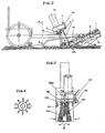
- the distributor according to the present invention preferably consists of two fixed walls 1, and two movable walls 19 placed at the end of a belt 2 and overlaying, laterally to said belt, having their fulcrum in 3, as shown in figures 1 and 2, at the upper end of the same on the sides of the belt and hanging downwards.
- Said walls are controlled through an electrovalve by a pneumatic jack M1 acting onto a system with two mechanical arms 5 opening at 90° angles and counterposed, connected at the lower end thereof to the two movable walls 19 by means of arms 4.
- two vertical rotors 10 having a rotation axis vertical to the sliding plane of the small cubes, said rotors rotating, by means of an oleodynamic motor 21, in a sense concordant towards the centre and opposite to the moving sense of the machine, the motion is discontinuous with intervals that are corresponding to the number of the distributed soil blocks.
- the motor operates through a couple of equal gearings, provided inside a box 6, creating two outcoming shafts rotating concordant in the centre.
- two small shafts are projecting, coupled by two transmission articulations 7 to said two rotors 10, that allow the rotation thereof even allowing a basculation at the lower end of the same.
- This is made possible due to a couple of hinges 8 and 17, placed at the same distance and parallel to each other, at a distance corresponding to the one existing between the two gearings and therefore to the two rotation axis', while from the lateral view of figure 2 they seem to be parallel to the belt.
- the hinges guide the small shafts 14 to the beginning of the rotors and allow the same the sole transversal basculation, making them remain rigid in longitudinal sense so as to support the push of the sods.
- the small arms are transversally interconnected with an opening of 90°, shown in 12, that unites at the centre, at the height of the hinges, where they come together to one single articulation. Said articulation, connected to a jack M2, maintains the elastic closing of the rotors 10 with a force variable according to the determined pressure.
- One of the two arms 15 has, beyond the mentioned connection opening, a second one 16 that transfers the motion and controls, by the displacing of the rotor 10, the piloting transducer 11 of the system.
- the use in this detail of two jacks M1 and M2 is preferreable as it allows, when compared to the mechanical springs that however can be used in this case, to manage the forces so as to make the system appliable to any kind of soil block, be it soft and wet as well as hard and dry, wihout damaging it or creating any disadvantage.
- Said rotors 10, provided with longitudinal tongues for assuring a better grasping and traction are usually closed at a width smaller to the one of the soil block, get open only when the entering soil block performs a pressure from the centre.
- the already mentioned transducer 11 operates onto said opening, whereby said transducer - by means of an electronic card - directly pilots the valve of the jack M1 operating onto the movable blocking walls 19 of the second soil block; at the same time, said card elaborates the signal and pilots also the stop of the rotors 10.
- the whole distributor system is received, at its lower end, by the ploughshare, wide enough.
- the ploughshare 18 prepares a furrow at the desired and always constant depth, guaranteed by the back consolidation small wheels 9, that make oscillate the transplanting element linked by a hinge to the upper end of the belt; after having placed the sods, the earthing up trowels 13 close the furrow.
- the device according to the present invention consists of a smooth transporting belt 2 provided at its sides with lateral fixed walls 1 forming, together with said belt, an inclined channel movable backwards with respect to the driving sense, and downwads, carrying the soil blocks resting on their bases with the seedlings turned upwards.
- the soil blocks are inserted with different methods and systems, and then the row of soil blocks advances inside the rod distributor according to the present invention.
- an apposite compressor moved with cardan shaft and with a different power transmission, provides a sufficient quantity and pressure of air so as to satisfy the whole distributor group, for as many as they are, predetermined and placed on the machine.
- an electronic impulse generator is provided, fixed onto the front roll or onto any other wheel according to the applications, and that an apposite decoding card operates, taught by distance data through a keyboard, at choice of the multiples of the emitted impulses, allowing also the quincunx deposition, and that the same controls the distributor.
- the outcoming of the soil block from the rotors 10 determines the pneumatic closing of the same; the relating impulse of the transducer 11 gives allowance to the jack M1 which, by means of a valve, operates onto the movable walls 19 which open and immediately free said soil block Z2, allowing its entrance between the rotors still moving after the precedent discharge; a new signal is given and a new grasping onto the precedent soil block occurs, with a consequent stop of the rotors 10, in the mentioned manner, so as to obtain a new separation.
- the following of the cycle determines an auto-phase that manages also the centering for the stop and separation of the soil blocks, which does not occur in already known devices, in which an apposite front mechanical rest for soil block Z1 determines its phase of stop and separation.
- the separation occur in an area different from the predetermined one, due to a malformation of the soil block or similar, the tangential grasping of the rotors on the same would crumble the soil block until the next advances, but without being able to pull the first one inside; and only with the arrival of a new and correct angle the rotors could take a grasp and would start pulling, thus starting the cycle.
- This allows the machine to avoid expensive stops for the manual re-etablishment of the phase, eliminating that part of the crumbled soil block.
Landscapes
- Life Sciences & Earth Sciences (AREA)
- Soil Sciences (AREA)
- Environmental Sciences (AREA)
- Transplanting Machines (AREA)
- Sowing (AREA)
- Soil Working Implements (AREA)
Claims (10)
- Reihenverteiler, Modularbestandteil einer zum Umpflanzen vorgehenen Maschine, die in der Lage ist, gekeinmte Planzen in kubischen Schollen aus komprimiertem Substrat aus Torf oder syntetischer Art zu transportieren, von einander zu trennen, zu verteilen und in die Erde einzupflanzen, bestehend aus:dadurch gekennzeichnet, dass besagte Trennvorrichtung zwei Läufer (10) enthält, die quer und elastisch angelenkt sind, um seitlich die sich zwischen ihnen befindlichen Schollen (Z1) festzuhalten und zur Trennung und Einsetzung der Schollen in die Erde unter Mitarbeit der zwei besagten, beweglichen, seitlichen wände (19) und einen Wandler (11), der auf die Stellung der Läufer (10) anspricht, zur Fuhrung der Vorrichtung unter Mitarbeit mit einer elektronischen Karte, wobei besagte elektronische Karte dazu geeignet ist, das Signal besagten Wandlers (11) zu bearbeiten und auch das Anhalten der Läufer (10) und die Bewegung der Wände (19) hervorzurufen.einem Zubringerband (2) mit festen Seitenwänden (1) um die Schollen zusammenzuhalten und zu führen;ener Vorrichtung, um die Schollen voneinander zu trennen, wobei diese Vorrichung mit beweglichen seitenwänden (19) versehen ist;einem Pflug (18) um eine Furche zu bilden;Nachschubrädern (13);Kleinen Rädern (9) zum Abstützen auf dem Grund und zur kontrolle der Ablagetiefe der Schollen;
- Reihenverteiler nach Anspruch 1, dadurch gekennzeichnet, dass die besagten zwei beweglichen Wände (19) seitlich am Ende besagten Bandes (2) vorgesehen sind, und ihren Schwerpunkt (3) in ihrem oberen, äusseren Ende haben und nach unten zeigen, wobei besagte bewegliche Wände (19) normaleweise offen sind um den Durchgang der Schollen zu ermöglichen, wobei in diesem Zustand die Läufer (10) geschlossen sind, und zwar mit dem kleinsten Abstand, der geringer ist als die nächstliegende Scholle, und sich kreisförmig übereinstimmend fortwährend gegen die Mitte und in die, den beweglichen Wänden (19) gegenüberliegende Richtung bewegen; weiterhin gekennzeichnet dadurch, dass besagte Scholle, wenn sie sich zwischen den Läufern befindet, deren Öffnung hervorruft, die gross genug ist, um ihren Durchgang und ihr Festhalten zu erlauben.
- Reihenverteiler einheitlicher Art nach den vorhergehenden Patentanspruchen, dadurch gekennzeichnet, dass die Öffnung der Läufer (10), mittels Wandler (11) und einer zweckentsprechenden elektronischen Karte, die beweglichen Wände (19) zum Aufhalten der Schollen auf Höhe der Scholle (Z2) und das Anhalten der Läufer (10) hervorruft.
- Reihenverteiler einheitlicher Art nach den Ansprüchen 1 bis 3, dadurch gekennzeichnet, dass das Paar beweglicher Wände (19) die Scholle (Z2) auf Befehl des Wandlers (11) an der Öffnung blockiert, wobei die Öffnung durch die eintretende Scholle (Z1) hervogerufen wird, der sich bewegenden Läufer (10) damit die Fase des Stillstandes und der Trennung hervorruft, wobei auch der Nachschub der Schollen unterbrochen wird.
- Reihenverteiler einheitlicher Art nach den Ansprüchen 1 bis 4, dadurch gekennzeichnet, dass die Läufer (10) von dem gleichen Impuls auf die beweglichen Wände (19) den Befehl zum Anhalten erhalten, aber dass sie für wenige zehntel Grade ihre Umdrehung fortsetzen und dann stehen bleiben, wenn die beweglichen Wände (19) die Scholle (Z2) in die Erde eingesetzt und dadurch die Trennung von der vorhergehenden Scholle hervorgerufen haben.
- Reihenverteiler einheitlicher Art nach den Ansprüchen 1 bis 5, dadurch gekennzeichnet, dass die von den vorhergehenden getrennte Scholle (Z1) zwischen den Läufern haften bleibt, bis sie die Entblockung und die Entlastung, die ihr durch die elektronische Karte erteilt wird, erhält.
- Reihenverteiler einheitlicher Art nach den Anspruchen 1 bis 6, dadurch gekennzeichnet dass, sobald der Anlaufbefehl erteilt wird, sich die Läufer (10) in Bewegung setzen, wobei sie die Scholle direkt und genau in die Furch einsetzen und sich sofort danach schliessen und dabei mittels des Wandlers (11) ein neues elektronisches Kommando zur Öffnung der beweglichen Wände (19) hervorrufen um dadurch einer neuen Scholle den Eintritt zwischen die Läufer (10) zu ermöglichen.
- Reihenverteiler einheitlicher Art nach den Anspruchen 1 bis 7, dadurch gekennzeichnet, dass die Läufer (10) nach der Abgabe der Scholle ihre Umdrehung fortsetzen, wobei sie sich von Neuem beim Eintritt der neuen Scholle schliessen und öffnen wenn besagte Läufer (10) ihre Bewegung unterbrechen werden.
- Reihenverteiler einheitlicher Art nach den Anspruchen 1 bis 8, dadurch gekennzeichnet, dass sowohl die beweglichen Wände (19) als auch die Läufer (10) durch eine Schubkreft angetrieben werden, die auf die Schollen, unabhängig voneinander, und verschiedenartig mittels eines pneumatischen Systeme einwirkt, welches aus Elektroventilen und pneumatischen Jacks M1 und M2 besteht.
- Reihenverteiler einheitlicher Art nach den Anspruchen 1 bis 9, dadurch gekennzeichnet, dass die Läufer (10) im Kontaktbereich mit den Schollen aus vielen perimetralen Rippen, die in gleichbleibendem Abständen angeordnet sind, bestehen, um ein besseres Festhalten zu gewährleisten wobei sie in der Mitte einen Hohlraum bilden, der dazu geeignet ist, das Abstossen eventuellen rückstandigen Materials, durch den Kontakt mit der Scholle bedingt, hervorzurufen.
Applications Claiming Priority (2)
| Application Number | Priority Date | Filing Date | Title |
|---|---|---|---|
| ITMN920030 | 1992-11-03 | ||
| ITMN920030A IT1256590B (it) | 1992-11-03 | 1992-11-03 | Distributore finale per il trapianto di piantine all'interno di zolle cubico compresse di substrato torboso o sintetico tipo olandese |
Publications (2)
| Publication Number | Publication Date |
|---|---|
| EP0596841A1 EP0596841A1 (de) | 1994-05-11 |
| EP0596841B1 true EP0596841B1 (de) | 1998-04-29 |
Family
ID=11384375
Family Applications (1)
| Application Number | Title | Priority Date | Filing Date |
|---|---|---|---|
| EP93830431A Expired - Lifetime EP0596841B1 (de) | 1992-11-03 | 1993-10-29 | Reihenabgabevorrichtung für Pflanzung von Pflanzlingen in Erdtöpfen oder synthetisches Substrat |
Country Status (3)
| Country | Link |
|---|---|
| EP (1) | EP0596841B1 (de) |
| DE (1) | DE69318254T2 (de) |
| IT (1) | IT1256590B (de) |
Families Citing this family (8)
| Publication number | Priority date | Publication date | Assignee | Title |
|---|---|---|---|---|
| FR2801168B1 (fr) * | 1999-11-18 | 2002-10-31 | Regero Sa | Procede pour separer des mottes cubiques, dispositif pour la mise en oeuvre du procede et machine de plantation de plants en mottes comportant un tel dispositif |
| EP1222845B1 (de) * | 2001-01-12 | 2009-04-08 | Regero | Verfahren zum Trennen eckiger Setzlinge, Gerät zum Ausführen des Verfahrens und Pflanzmaschine mit einem solchen Gerät zum Pflanzen von Setzlingen |
| FR2819373B1 (fr) * | 2001-01-15 | 2003-04-18 | Regero Sa | Machine de plantation de plants en mottes, a cadence elevee |
| FR2834608B1 (fr) * | 2002-01-16 | 2004-07-30 | Regero Sa | Procede de plantation de plants en mottes et module de plantation pour sa mise en oeuvre |
| ITCR20050015A1 (it) * | 2005-11-11 | 2007-05-12 | Ferrari Cost Mecc Snc | Distributore automatico per trapiantatrici |
| CN101305656B (zh) * | 2008-07-05 | 2010-06-23 | 郭瑞鸿 | 钵苗移植机 |
| ITUB20160297A1 (it) | 2016-01-19 | 2017-07-19 | Ferrari Costruzioni Mecc S R L | Macchina trapiantatrice di piantine radicate in zolle perfezionata |
| RU201497U1 (ru) * | 2020-08-03 | 2020-12-18 | федеральное государственное бюджетное образовательное учреждение высшего образования "Пензенский государственный аграрный университет" | Роторно-лопастное ориентирующее устройство высадкопосадочной машины |
Family Cites Families (3)
| Publication number | Priority date | Publication date | Assignee | Title |
|---|---|---|---|---|
| DE3115006A1 (de) * | 1981-04-14 | 1982-10-28 | Reinhold 4520 Melle Heilmann | Pflanzmaschine |
| US4597343A (en) * | 1982-02-09 | 1986-07-01 | Nippon Tensaiseito Kabushiki Kaisha | Continuous paper-tube potted-seedlings separation transplanting planting machine |
| FR2666486B1 (fr) * | 1990-09-11 | 1994-05-20 | Regero | Perfectionnement au systeme de plantation pour planteuse. |
-
1992
- 1992-11-03 IT ITMN920030A patent/IT1256590B/it active IP Right Grant
-
1993
- 1993-10-29 EP EP93830431A patent/EP0596841B1/de not_active Expired - Lifetime
- 1993-10-29 DE DE69318254T patent/DE69318254T2/de not_active Expired - Lifetime
Also Published As
| Publication number | Publication date |
|---|---|
| EP0596841A1 (de) | 1994-05-11 |
| IT1256590B (it) | 1995-12-11 |
| ITMN920030A1 (it) | 1994-05-03 |
| DE69318254T2 (de) | 1998-11-05 |
| DE69318254D1 (de) | 1998-06-04 |
| ITMN920030A0 (it) | 1992-11-03 |
Similar Documents
| Publication | Publication Date | Title |
|---|---|---|
| US3343507A (en) | Planter | |
| KR960002939B1 (ko) | 야채이식기 | |
| US4886002A (en) | Transplanting machine | |
| EP0135004B1 (de) | Umpflanzmaschine mit Pflänzlingsauswahlvorrichtung | |
| US4627190A (en) | Apparatus for planting seed in seed germinating tray | |
| FI81478C (fi) | Planteringsmaskin foer plantering av krukplantor som avskilts fraon en kontinuerlig ked av pappershylsor. | |
| EP0596841A1 (de) | Reihenabgabevorrichtung für Pflanzung von Pflanzlingen in Erdtöpfen oder synthetisches Substrat | |
| US5121701A (en) | Transplating apparatus | |
| WO1987004585A1 (en) | Seedling planting machine | |
| US4355588A (en) | Transplanting machine | |
| AU2010200555A1 (en) | Transplanting apparatus | |
| CN100389644C (zh) | 苗移植机 | |
| EP3195712B1 (de) | Eine verbesserte transplantermaschine für setzlinge mit wurzelballen | |
| US2333945A (en) | Automatic transplanter | |
| EP0433075B1 (de) | Pflanzensetzmaschine | |
| US4404917A (en) | Method and device for planting plants | |
| WO2007091221A2 (en) | Semi-authomatic transplanter machine for woody cuttings | |
| EP0088518A1 (de) | Pflanzmaschine | |
| JPH0236328Y2 (de) | ||
| JPH051704B2 (de) | ||
| JP2838681B2 (ja) | 多条移植機 | |
| JPS62122509A (ja) | 移植装置 | |
| CN120858716A (zh) | 一种用于草莓苗种植用移栽机 | |
| SU1739881A1 (ru) | Селекционна се лка | |
| McLaughlin et al. | A Microplot Seeder 1 |
Legal Events
| Date | Code | Title | Description |
|---|---|---|---|
| PUAI | Public reference made under article 153(3) epc to a published international application that has entered the european phase |
Free format text: ORIGINAL CODE: 0009012 |
|
| AK | Designated contracting states |
Kind code of ref document: A1 Designated state(s): BE DE FR NL |
|
| 17P | Request for examination filed |
Effective date: 19941102 |
|
| 17Q | First examination report despatched |
Effective date: 19960723 |
|
| GRAG | Despatch of communication of intention to grant |
Free format text: ORIGINAL CODE: EPIDOS AGRA |
|
| GRAG | Despatch of communication of intention to grant |
Free format text: ORIGINAL CODE: EPIDOS AGRA |
|
| GRAH | Despatch of communication of intention to grant a patent |
Free format text: ORIGINAL CODE: EPIDOS IGRA |
|
| RAP1 | Party data changed (applicant data changed or rights of an application transferred) |
Owner name: FERRARI COSTRUZIONI MECCANICHE DI FERRARI FRANCESC |
|
| GRAH | Despatch of communication of intention to grant a patent |
Free format text: ORIGINAL CODE: EPIDOS IGRA |
|
| GRAA | (expected) grant |
Free format text: ORIGINAL CODE: 0009210 |
|
| AK | Designated contracting states |
Kind code of ref document: B1 Designated state(s): BE DE FR NL |
|
| RIN1 | Information on inventor provided before grant (corrected) |
Inventor name: FERRARI, LUIGI |
|
| REF | Corresponds to: |
Ref document number: 69318254 Country of ref document: DE Date of ref document: 19980604 |
|
| ET | Fr: translation filed | ||
| PLBE | No opposition filed within time limit |
Free format text: ORIGINAL CODE: 0009261 |
|
| STAA | Information on the status of an ep patent application or granted ep patent |
Free format text: STATUS: NO OPPOSITION FILED WITHIN TIME LIMIT |
|
| 26N | No opposition filed | ||
| PGFP | Annual fee paid to national office [announced via postgrant information from national office to epo] |
Ref country code: BE Payment date: 20121025 Year of fee payment: 20 Ref country code: DE Payment date: 20121029 Year of fee payment: 20 Ref country code: FR Payment date: 20121107 Year of fee payment: 20 |
|
| PGFP | Annual fee paid to national office [announced via postgrant information from national office to epo] |
Ref country code: NL Payment date: 20121024 Year of fee payment: 20 |
|
| REG | Reference to a national code |
Ref country code: DE Ref legal event code: R071 Ref document number: 69318254 Country of ref document: DE |
|
| BE20 | Be: patent expired |
Owner name: *FERRARI COSTRUZIONI MECCANICHE DI FERRARI FRANCES Effective date: 20131029 |
|
| REG | Reference to a national code |
Ref country code: NL Ref legal event code: V4 Effective date: 20131029 |
|
| PG25 | Lapsed in a contracting state [announced via postgrant information from national office to epo] |
Ref country code: DE Free format text: LAPSE BECAUSE OF EXPIRATION OF PROTECTION Effective date: 20131030 |