EP0596845A1 - Fusée de proximité magnétique - Google Patents
Fusée de proximité magnétique Download PDFInfo
- Publication number
- EP0596845A1 EP0596845A1 EP93850198A EP93850198A EP0596845A1 EP 0596845 A1 EP0596845 A1 EP 0596845A1 EP 93850198 A EP93850198 A EP 93850198A EP 93850198 A EP93850198 A EP 93850198A EP 0596845 A1 EP0596845 A1 EP 0596845A1
- Authority
- EP
- European Patent Office
- Prior art keywords
- proximity fuse
- magnetic field
- sensing
- sensors
- charge carrier
- Prior art date
- Legal status (The legal status is an assumption and is not a legal conclusion. Google has not performed a legal analysis and makes no representation as to the accuracy of the status listed.)
- Granted
Links
- 230000005291 magnetic effect Effects 0.000 title claims abstract description 45
- 239000002800 charge carrier Substances 0.000 claims abstract description 14
- 230000005294 ferromagnetic effect Effects 0.000 claims abstract description 12
- 230000000977 initiatory effect Effects 0.000 claims abstract description 3
- 230000004907 flux Effects 0.000 claims description 12
- XEEYBQQBJWHFJM-UHFFFAOYSA-N Iron Chemical compound [Fe] XEEYBQQBJWHFJM-UHFFFAOYSA-N 0.000 description 6
- 238000010586 diagram Methods 0.000 description 3
- 238000011156 evaluation Methods 0.000 description 3
- 229910052742 iron Inorganic materials 0.000 description 3
- 230000005672 electromagnetic field Effects 0.000 description 2
- 239000002184 metal Substances 0.000 description 2
- 229910052751 metal Inorganic materials 0.000 description 2
- 239000005030 aluminium foil Substances 0.000 description 1
- 238000001514 detection method Methods 0.000 description 1
- 230000000694 effects Effects 0.000 description 1
- 230000035945 sensitivity Effects 0.000 description 1
Images

Classifications
-
- F—MECHANICAL ENGINEERING; LIGHTING; HEATING; WEAPONS; BLASTING
- F42—AMMUNITION; BLASTING
- F42C—AMMUNITION FUZES; ARMING OR SAFETY MEANS THEREFOR
- F42C13/00—Proximity fuzes; Fuzes for remote detonation
- F42C13/08—Proximity fuzes; Fuzes for remote detonation operated by variations in magnetic field
Definitions
- the present invention relates to a magnetic proximity fuse for initiating the charging of a moving charge carrier, for example a guided missile, projectile, grenade or the like, when it passes at a certain distance from a ferromagnetic object.
- a moving charge carrier for example a guided missile, projectile, grenade or the like
- the proximity fuse has a transmitter unit with a generator coil which generates an electromagnetic field which is distributed in space in accordance with known laws.
- the proximity fuse also includes a receiver unit in the form of a sensor coil which is placed separately from the generator coil. When the sensor coil is affected by an electromagnetic field, an electromotive force is induced in the coil. When there is a metal object located in the field from the transmitter unit, eddy currents are induced in its surface. These eddy currents generate a secondary field which is detected by the receiver unit.
- the range is determined by the output power of the transmitter unit and the sensitivity of the receiver unit.
- a "typical" range is 0.5 - 1.5 m.
- a passive magnetic proximity fuse utilises the fact that the terrestrial magnetic field is deformed around ferromagnetic objects, for example large objects of iron, for example military tanks and bodies of iron ore.
- the proximity fuse includes a sensing system in the form of sensors for flux density, and a signal processing section for evaluating the signals. This is due to the fact that changes caused, for example, by a tank in the terrestrial magnetic field are comparable to signals which are obtained in the charge carrier. Moreover, a longer range can be obtained since the distance dependence only increases with r ⁇ 3. At a distance of 3 metres from an iron object of the size of a tank, the effect is of the order of magnitude of 5%, which is sufficient for detection.
- the object of this invention is to produce a magnetic proximity fuse without an active part, that is to say a passive magnetic proximity fuse with a greater range than the active proximity fuses known earlier.
- One or more sensors in the form of coils or flux gate sensors sense deviations in the flux density of the terrestrial magnetic field. Furthermore, position-sensing elements, gyros or accelerometers, are arranged on the charge carrier and sense its movements. The sensor signals and, respectively, position signals are supplied to the signal processing, which outputs an active output signal in association with a deviation in the terrestrial magnetic field, which signal is compensated for the charge carrier's own movement in the terrestrial magnetic field, so that the active output signal only occurs in dependence on deviations in the terrestrial magnetic field which are occasioned by ferromagnetic objects.
- a proximity fuse of this type Using a proximity fuse of this type, a greater range is obtained than with an active proximity fuse, and resistance to interference is improved.
- Figure 1 diagrammatically shows a moving charge carrier in the form of a missile 1 which is moving in the terrestrial magnetic field B.
- the front part of the missile is equipped with a proximity fuse 2 which is to sense if a ferromagnetic object, for example a tank 3, is located in the vicinity of the missile and then output an output signal for triggering the effective part of the missile.
- the proximity fuse 2 consists of a passive magnetic proximity fuse with sensors for the terrestrial magnetic field B.
- an orthogonal missile-fixed coordinate system with the XYZ axes according to the figure is introduced, that is to say the X axis coincides with the longitudinal axis of the missile, the Y axis is at right angles to the side and the Z axis is at right angles downwards.
- the position and movement of the missile can be described with the aid of the roll, pitch and yaw angles ⁇ , ⁇ and ⁇ , defined as follows:
- the roll angle ⁇ specifies a turning around the X axis.
- the angle is positive with a Y-Z turning, that is to say clockwise seen from the back of the missile.
- the pitch angle ⁇ specifies a turning around the Y axis.
- the angle is positive with a X-Z turning, that is to say missile nose up.
- the yaw angle ⁇ specifies a turning around the Z axis.
- the angle is positive with an X-Y turning, that is to say yawing to the right.
- the sensors are made up of three orthogonal sensors, that is to say the sensors directed in the X, Y and Z directions.
- the three sensors then sense the flux densities B X , B Y and B Z .
- Certain sensors for example flux gate sensors, provide B X , B Y and B Z directly.
- Other sensors of the coil type provide the time derivative of the B field and B X , B Y and B Z must then be calculated by solving the system of equations.
- the disturbance of the terrestrial magnetic field by the target can be represented by a magnetic dipole.
- the orientation of the dipole depends on the direction of the terrestrial magnetic field. If the terrestrial magnetic field is horizontal the axis of the dipole becomes horizontal. If the terrestrial magnetic field is vertical, the axis of the dipole becomes vertical and if the terrestrial magnetic field is then horizontal the axis of the dipole becomes horizontal.
- the proximity fuse includes a signal processor 5 which is arranged to compensate for the missile's own movements in the terrestrial magnetic field so that an active output signal only occurs in dependence on those deviations in the terrestrial magnetic field which are occasioned by a ferromagnetic object (the target).
- the missile therefore includes position-sensing elements 6, for example gyros, which sense the movement of the missile and the output signal, the gyro signal, is supplied to the signal processor for evaluation, see Figure 2.
- Figure 2 shows a block diagram of the main parts of the proximity fuse.
- Three sensors 4 measure the magnetic flux densities B X , B Y and B Z .
- the sensor signals are supplied via amplifiers 7 and A/D convertors 8 to the signal processor in the form of a microprocessor 9 for evaluation.
- the microprocessor is also supplied with gyro signals from the gyro 6 which senses the missile's own movement.
- the proximity fuse is intended to operate as follows:
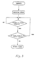
- the three components in the terrestrial magnetic field B are measured. From these values, the magnitude and direction of the terrestrial magnetic field are calculated.
- the magnitude of the magnetic field B X , B Y and B Z is continuously measured and compared with the original values. If a deviation occurs, that is to say a change in the magnetic field which cannot be explained by a movement of the missile, it is known that there is a ferromagnetic object in the vicinity, that is to say the target has been encountered, and the proximity fuse outputs an output signal to the effective part.
Landscapes
- Engineering & Computer Science (AREA)
- General Engineering & Computer Science (AREA)
- Measuring Magnetic Variables (AREA)
- Control Of Position, Course, Altitude, Or Attitude Of Moving Bodies (AREA)
- Aiming, Guidance, Guns With A Light Source, Armor, Camouflage, And Targets (AREA)
- Manipulator (AREA)
- Radar Systems Or Details Thereof (AREA)
Applications Claiming Priority (2)
| Application Number | Priority Date | Filing Date | Title |
|---|---|---|---|
| SE9203256A SE9203256L (sv) | 1992-11-04 | 1992-11-04 | Magnetiskt zonrör |
| SE9203256 | 1992-11-04 |
Publications (2)
| Publication Number | Publication Date |
|---|---|
| EP0596845A1 true EP0596845A1 (fr) | 1994-05-11 |
| EP0596845B1 EP0596845B1 (fr) | 1998-05-27 |
Family
ID=20387674
Family Applications (1)
| Application Number | Title | Priority Date | Filing Date |
|---|---|---|---|
| EP93850198A Expired - Lifetime EP0596845B1 (fr) | 1992-11-04 | 1993-10-20 | Fusée de proximité magnétique |
Country Status (6)
| Country | Link |
|---|---|
| US (1) | US5423262A (fr) |
| EP (1) | EP0596845B1 (fr) |
| JP (1) | JP3373016B2 (fr) |
| DE (1) | DE69318801T2 (fr) |
| ES (1) | ES2115745T3 (fr) |
| SE (1) | SE9203256L (fr) |
Cited By (5)
| Publication number | Priority date | Publication date | Assignee | Title |
|---|---|---|---|---|
| DE4419355A1 (de) * | 1994-06-03 | 1995-12-07 | Telefunken Microelectron | Verfahren zur Detektion von Straßen- und Schienenfahrzeugen |
| RU2323408C2 (ru) * | 2006-03-03 | 2008-04-27 | Пензенский Артиллерийский Инженерный Институт | Способ унификации взрывателей |
| EP3208570A1 (fr) * | 2016-02-16 | 2017-08-23 | BAE Systems PLC | Amorce pour projectile |
| WO2017141009A1 (fr) * | 2016-02-16 | 2017-08-24 | Bae Systems Plc | Système d'amorce de projectile |
| US10900763B2 (en) | 2016-02-16 | 2021-01-26 | Bae Systems Plc | Activating a fuse |
Families Citing this family (8)
| Publication number | Priority date | Publication date | Assignee | Title |
|---|---|---|---|---|
| DE19854608C2 (de) * | 1998-05-28 | 2000-11-30 | Daimler Chrysler Ag | Zündeinrichtung für Penetratoren |
| US6779463B2 (en) * | 2001-11-27 | 2004-08-24 | Armtec Defense Products Company | Sabot-launched delivery apparatus for non-lethal payload |
| US7363861B2 (en) * | 2004-08-13 | 2008-04-29 | Armtec Defense Products Co. | Pyrotechnic systems and associated methods |
| US8146502B2 (en) | 2006-01-06 | 2012-04-03 | Armtec Defense Products Co. | Combustible cartridge cased ammunition assembly |
| US20100274544A1 (en) * | 2006-03-08 | 2010-10-28 | Armtec Defense Products Co. | Squib simulator |
| US7913625B2 (en) * | 2006-04-07 | 2011-03-29 | Armtec Defense Products Co. | Ammunition assembly with alternate load path |
| DE102013017331A1 (de) * | 2013-10-17 | 2015-04-23 | Bundesrepublik Deutschland, vertreten durch das BMVg, vertreten durch das Bundesamt für Ausrüstung, Informationstechnik und Nutzung der Bundeswehr | Verfahren zur Initiierung einer Wirkladung eines Sprenggeschosses und Zünder hierzu |
| US10935357B2 (en) | 2018-04-25 | 2021-03-02 | Bae Systems Information And Electronic Systems Integration Inc. | Proximity fuse having an E-field sensor |
Citations (2)
| Publication number | Priority date | Publication date | Assignee | Title |
|---|---|---|---|---|
| DE3503919C1 (de) * | 1985-02-06 | 1986-07-03 | Messerschmitt-Bölkow-Blohm GmbH, 8012 Ottobrunn | Einrichtung zur Ausloesung einer Mine mit einem als Kugel oder Rotationskoerper ausgebildeten Gehaeuse |
| GB2240384A (en) * | 1982-01-20 | 1991-07-31 | Emi Ltd | Fuzing systems. |
Family Cites Families (5)
| Publication number | Priority date | Publication date | Assignee | Title |
|---|---|---|---|---|
| GB1050490A (fr) * | 1961-12-23 | |||
| US4123019A (en) * | 1976-11-10 | 1978-10-31 | Martin Marietta Corporation | Method and system for gravity compensation of guided missiles or projectiles |
| GB1581944A (en) * | 1977-04-12 | 1980-12-31 | Cosan Crisplant As | Or supported carts conveyor system including an overhead drive system for flo |
| SE426269B (sv) * | 1981-05-06 | 1982-12-20 | Bofors Ab | Anordning vid detektering av metallforemal |
| FR2631694B1 (fr) * | 1988-05-19 | 1993-07-16 | Clausin Jacques | Dispositif de mise de feu a effet de proximite de charges explosives a effet dirige |
-
1992
- 1992-11-04 SE SE9203256A patent/SE9203256L/ not_active IP Right Cessation
-
1993
- 1993-10-20 ES ES93850198T patent/ES2115745T3/es not_active Expired - Lifetime
- 1993-10-20 EP EP93850198A patent/EP0596845B1/fr not_active Expired - Lifetime
- 1993-10-20 DE DE69318801T patent/DE69318801T2/de not_active Expired - Fee Related
- 1993-10-28 JP JP29471193A patent/JP3373016B2/ja not_active Expired - Fee Related
- 1993-11-03 US US08/145,178 patent/US5423262A/en not_active Expired - Lifetime
Patent Citations (2)
| Publication number | Priority date | Publication date | Assignee | Title |
|---|---|---|---|---|
| GB2240384A (en) * | 1982-01-20 | 1991-07-31 | Emi Ltd | Fuzing systems. |
| DE3503919C1 (de) * | 1985-02-06 | 1986-07-03 | Messerschmitt-Bölkow-Blohm GmbH, 8012 Ottobrunn | Einrichtung zur Ausloesung einer Mine mit einem als Kugel oder Rotationskoerper ausgebildeten Gehaeuse |
Cited By (7)
| Publication number | Priority date | Publication date | Assignee | Title |
|---|---|---|---|---|
| DE4419355A1 (de) * | 1994-06-03 | 1995-12-07 | Telefunken Microelectron | Verfahren zur Detektion von Straßen- und Schienenfahrzeugen |
| RU2323408C2 (ru) * | 2006-03-03 | 2008-04-27 | Пензенский Артиллерийский Инженерный Институт | Способ унификации взрывателей |
| EP3208570A1 (fr) * | 2016-02-16 | 2017-08-23 | BAE Systems PLC | Amorce pour projectile |
| WO2017141009A1 (fr) * | 2016-02-16 | 2017-08-24 | Bae Systems Plc | Système d'amorce de projectile |
| US20200116465A1 (en) * | 2016-02-16 | 2020-04-16 | Bae Systems Plc | Fuse system for projectile |
| US10746519B2 (en) | 2016-02-16 | 2020-08-18 | Bae Systems Plc | Fuse system for projectile |
| US10900763B2 (en) | 2016-02-16 | 2021-01-26 | Bae Systems Plc | Activating a fuse |
Also Published As
| Publication number | Publication date |
|---|---|
| DE69318801T2 (de) | 1998-11-19 |
| JPH06207800A (ja) | 1994-07-26 |
| SE470289B (sv) | 1994-01-10 |
| EP0596845B1 (fr) | 1998-05-27 |
| DE69318801D1 (de) | 1998-07-02 |
| ES2115745T3 (es) | 1998-07-01 |
| SE9203256D0 (sv) | 1992-11-04 |
| JP3373016B2 (ja) | 2003-02-04 |
| US5423262A (en) | 1995-06-13 |
| SE9203256L (sv) | 1994-01-10 |
Similar Documents
| Publication | Publication Date | Title |
|---|---|---|
| EP0596845B1 (fr) | Fusée de proximité magnétique | |
| US5357437A (en) | Magnetic marker position fixing system for underwater vehicles | |
| US7342399B1 (en) | Magnetic anomaly sensing-based system for tracking a moving magnetic target | |
| EP3227728B1 (fr) | Système et procédé d'étude de fonds marins | |
| US4309659A (en) | Method for detecting a magnetic source by measuring the magnetic field thereabout | |
| EP1813905B1 (fr) | Dispositif et procédé de détermination d'orientation de roulis d'un projectil | |
| US6421116B1 (en) | Method for determining the relative movement between missile and target | |
| WO1990012276A1 (fr) | Dispositif de mesure de position a courant continu | |
| US4600883A (en) | Apparatus and method for determining the range and bearing in a plane of an object characterized by an electric or magnetic dipole | |
| US11624612B2 (en) | Methods for measuring roll, pitch and yam angle and orientation misalignment in objects | |
| US20130001354A1 (en) | GPS independent guidance sensor system for gun-launched projectiles | |
| US4766385A (en) | Underwater buried mine classifier | |
| US4058275A (en) | Low frequency passive guidance method | |
| US20120313812A1 (en) | Scanning Polarized RF Reference Sources For Angular Orientation Measurement For Munitions and the Like | |
| EP3508811A1 (fr) | Système de détection d'orientation de véhicule | |
| US5463523A (en) | Zero field degaussing system and method | |
| EP0242391B1 (fr) | Systeme magnetique a reglage automatique utilise pour la demagnetisation des navires | |
| US3653351A (en) | Magnetic detector | |
| US5425001A (en) | Navigation system for an underwater vehicle | |
| US5740986A (en) | Method of determining the position of roll of a rolling flying object | |
| DE19611757C1 (de) | Verfahren und Meßanordnung zur Ortung von im Erdreich befindlichen Objekten | |
| KR20260018754A (ko) | 지하 매설물 탐지용 비행체 및 이를 이용하는 지하 매설물 탐지 방법 | |
| RU2254542C1 (ru) | Способ наведения летательного аппарата на интенсивно маневрирующую воздушную цель | |
| JPH0246913B2 (fr) | ||
| US5450805A (en) | Warhead influence |
Legal Events
| Date | Code | Title | Description |
|---|---|---|---|
| PUAI | Public reference made under article 153(3) epc to a published international application that has entered the european phase |
Free format text: ORIGINAL CODE: 0009012 |
|
| AK | Designated contracting states |
Kind code of ref document: A1 Designated state(s): DE ES FR GB IT |
|
| 17P | Request for examination filed |
Effective date: 19941102 |
|
| 17Q | First examination report despatched |
Effective date: 19960624 |
|
| GRAG | Despatch of communication of intention to grant |
Free format text: ORIGINAL CODE: EPIDOS AGRA |
|
| GRAG | Despatch of communication of intention to grant |
Free format text: ORIGINAL CODE: EPIDOS AGRA |
|
| GRAG | Despatch of communication of intention to grant |
Free format text: ORIGINAL CODE: EPIDOS AGRA |
|
| GRAH | Despatch of communication of intention to grant a patent |
Free format text: ORIGINAL CODE: EPIDOS IGRA |
|
| GRAH | Despatch of communication of intention to grant a patent |
Free format text: ORIGINAL CODE: EPIDOS IGRA |
|
| GRAA | (expected) grant |
Free format text: ORIGINAL CODE: 0009210 |
|
| AK | Designated contracting states |
Kind code of ref document: B1 Designated state(s): DE ES FR GB IT |
|
| ITF | It: translation for a ep patent filed | ||
| ET | Fr: translation filed | ||
| REG | Reference to a national code |
Ref country code: ES Ref legal event code: FG2A Ref document number: 2115745 Country of ref document: ES Kind code of ref document: T3 |
|
| REF | Corresponds to: |
Ref document number: 69318801 Country of ref document: DE Date of ref document: 19980702 |
|
| PLBE | No opposition filed within time limit |
Free format text: ORIGINAL CODE: 0009261 |
|
| STAA | Information on the status of an ep patent application or granted ep patent |
Free format text: STATUS: NO OPPOSITION FILED WITHIN TIME LIMIT |
|
| 26N | No opposition filed | ||
| REG | Reference to a national code |
Ref country code: GB Ref legal event code: IF02 |
|
| REG | Reference to a national code |
Ref country code: GB Ref legal event code: 732E |
|
| REG | Reference to a national code |
Ref country code: ES Ref legal event code: PC2A |
|
| REG | Reference to a national code |
Ref country code: FR Ref legal event code: TP |
|
| PGFP | Annual fee paid to national office [announced via postgrant information from national office to epo] |
Ref country code: DE Payment date: 20081016 Year of fee payment: 16 |
|
| PGFP | Annual fee paid to national office [announced via postgrant information from national office to epo] |
Ref country code: ES Payment date: 20081121 Year of fee payment: 16 |
|
| PGFP | Annual fee paid to national office [announced via postgrant information from national office to epo] |
Ref country code: IT Payment date: 20081028 Year of fee payment: 16 |
|
| PGFP | Annual fee paid to national office [announced via postgrant information from national office to epo] |
Ref country code: FR Payment date: 20081014 Year of fee payment: 16 |
|
| PGFP | Annual fee paid to national office [announced via postgrant information from national office to epo] |
Ref country code: GB Payment date: 20081015 Year of fee payment: 16 |
|
| REG | Reference to a national code |
Ref country code: FR Ref legal event code: ST Effective date: 20100630 |
|
| PG25 | Lapsed in a contracting state [announced via postgrant information from national office to epo] |
Ref country code: FR Free format text: LAPSE BECAUSE OF NON-PAYMENT OF DUE FEES Effective date: 20091102 Ref country code: DE Free format text: LAPSE BECAUSE OF NON-PAYMENT OF DUE FEES Effective date: 20100501 |
|
| PG25 | Lapsed in a contracting state [announced via postgrant information from national office to epo] |
Ref country code: GB Free format text: LAPSE BECAUSE OF NON-PAYMENT OF DUE FEES Effective date: 20091020 |
|
| PG25 | Lapsed in a contracting state [announced via postgrant information from national office to epo] |
Ref country code: IT Free format text: LAPSE BECAUSE OF NON-PAYMENT OF DUE FEES Effective date: 20091020 |
|
| REG | Reference to a national code |
Ref country code: ES Ref legal event code: FD2A Effective date: 20110707 |
|
| PG25 | Lapsed in a contracting state [announced via postgrant information from national office to epo] |
Ref country code: ES Free format text: LAPSE BECAUSE OF NON-PAYMENT OF DUE FEES Effective date: 20110627 |
|
| PG25 | Lapsed in a contracting state [announced via postgrant information from national office to epo] |
Ref country code: ES Free format text: LAPSE BECAUSE OF NON-PAYMENT OF DUE FEES Effective date: 20091021 |