EP0597009B1 - Vorrichtung zum zurückhalten eines fahrzeugs - Google Patents
Vorrichtung zum zurückhalten eines fahrzeugs Download PDFInfo
- Publication number
- EP0597009B1 EP0597009B1 EP92917031A EP92917031A EP0597009B1 EP 0597009 B1 EP0597009 B1 EP 0597009B1 EP 92917031 A EP92917031 A EP 92917031A EP 92917031 A EP92917031 A EP 92917031A EP 0597009 B1 EP0597009 B1 EP 0597009B1
- Authority
- EP
- European Patent Office
- Prior art keywords
- vehicle
- vehicle restraint
- ram
- hydraulic cylinder
- restraint
- Prior art date
- Legal status (The legal status is an assumption and is not a legal conclusion. Google has not performed a legal analysis and makes no representation as to the accuracy of the status listed.)
- Expired - Lifetime
Links
Images


Classifications
-
- B—PERFORMING OPERATIONS; TRANSPORTING
- B65—CONVEYING; PACKING; STORING; HANDLING THIN OR FILAMENTARY MATERIAL
- B65G—TRANSPORT OR STORAGE DEVICES, e.g. CONVEYORS FOR LOADING OR TIPPING, SHOP CONVEYOR SYSTEMS OR PNEUMATIC TUBE CONVEYORS
- B65G69/00—Auxiliary measures taken, or devices used, in connection with loading or unloading
- B65G69/003—Restraining movement of a vehicle at a loading station using means not being part of the vehicle
Definitions
- the prior art locking devices are subject to being struck by the parking vehicle, particularly if the vehicle has a low clearance.
- the prior art devices When used in conjunction with certain dock levellers capable of extending down to the ground level, the prior art devices also can present an obstacle to the movement of certain equipment, e.g., the dock leveller and fork lift trucks.
- the prior art devices also typically are limited to a specified range of height for the ICC bar of vehicle for an effective restraint to occur.
- Other problems with the prior art locking devices include the inability to provide a secure restraint over an acceptable range of horizontal distance between the ICC bar and the loading dock wall.
- a further disadvantage of the prior art is an inability of the hook to provide angular adaptation to fully engage the ICC bar if the vehicle is not parked at right angles to the loading dock.
- US-A-4735542 discloses a truck restraining device having a casing that projects above the ground and accommodates a restraining member movable between a retracted position in which the member projects a minimum amount from the casing and an extended position in which the restraining member engages a truck.
- a sensing rod detects the presence of a truck.
- a still further,object of the invention is to provide a vehicle restraint which, when stored below ground, leaves a top surface which is flush with the ground to permit equipment such as a fork lift truck to move above the restraint without obstruction while at the same time preventing any part of the equipment from falling below the ground level.
- a still further object of the invention is to provide doors for closing above the vehicle restraint when in a stored position, which doors protect the vehicle restraint while at the same tine providing a surface flush with the ground.
- a still further object of the invention is to provide a stepped hook with a stepped sensor to provide various vertical heights at which the hook will engage the ICC bar of a vehicle and also to provide various steps spaced horizontally to engage the ICC bar and to prevent the vehicle from gaining a "running start" in which the vehicle gains speed while moving away from the loading dock.
- a still further object of the invention is to provide a vehicle restraint which provides for angular adaptation of the hook to permit the hook to fully engage the ICC bar even if the vehicle is not parked at right angles to the loading dock.
- a vehicle restraint comprising a member mounted for reciprocating movement relative to the ground between a first stored position and a second raised position, a ram for moving said member in a substantially vertical direction between said first stored position and said second raised position, and a sensor means for detecting engagement between the restraint and a vehicle characterized in that said ram is slidably mounted in a housing subscantially disposed below ground, said housing having an opening in the top thereof substantially at ground level, said ram in said stored position being inside the housing, and a hook assembly being attached to said ram and having a step-like profile comprising a plurality of steps, each step having a substantially vertical rise for releasably engaging a vehicle when said ram is in said second raised position, said hook assembly being stored within said housing when said ram is in the first stored position, said sensor sensing engagement between said hook assembly and a vehicle.
- a hook assembly for use in a vehicle restraint, characterized in that said hook assembly comprises a hook having a step-like profile comprised of a plurality of steps, each step having substantially vertical rise for releasably engaging a vehicle, and sensor means having the same stepped profile as the hook and pivotally mounted thereto so that the sensor also engages the vehicle as the hook moves into engagement with the vehicle to indicate engagement of the vehicle.
- Figure 1a is a fragmentary perspective view of the improved vehicle restraint in a below-ground stored position near the front wall of a loading dock.
- FIG. 1b is similar to FIG. 1a, except that the vehicle restraint is in a raised position above the ground.
- FIG. 1c is similar to FIG. 1a, except that the dock leveler is shown in the down position.
- FIG. 2 is a fragmentary perspective view of the vehicle restraint emerging from the stored position.
- FIG. 3 is a fragmentary perspective view of the vehicle restraint showing the hook assembly with a sensor in an extended position.
- FIG. 4 is similar to FIG. 3 except that the sensor is shown in a depressed position.
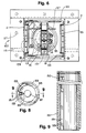
- FIG. 5 is a rear elevational view of the vehicle restraint in a stored position (doors shown open for clarity).
- FIG. 6 is a top plan view of the vehicle restraint shown in FIG. 5.
- FIG. 7 is a sectional view of the device taken along line 7--7 of FIG. 5.
- FIG. 8 is a fragmentary top plan view of the device of FIG. 5 and having portions removed to expose concealed components thereof.
- FIG. 9 is a sectional view of the device taken along line 9--9 of FIG. 8.
- FIG. 10 is a side elevational view of the hook assembly of the device.
- FIG. 11 is a front elevational view of the hook assembly of FIG. 10.
- FIG. 12 is a top plan view of the hook assembly of FIG. 10.
- FIG. 1a also illustrates an example of a loading dock 5 with which the invention might be used.
- the loading dock 5 shown in FIG. 1a typically includes a concrete dock floor 7 and a vertical wall 9 on which a pair of rubber bumpers 11 are mounted.
- the loading dock 5 may advantageously be provided with a dock leveler 13 including a steel plate 15 which is normally stored in a position flush with the loading dock floor 7.
- the dock leveler 13 also has a steel lip 17 which can be pivotally extended away from the dock wall 9 to provide an extension from the loading dock to the vehicle.
- the dock leveler 13 may be of the type having a scissor lift, see U.S. Patent No. 4,995,130, issued to Hahn et al. Plastic bellows 19 may be provided to cover the scissor lift mechanism.
- the dock leveler 13 shown in FIG. 1a preferably is capable of being moved downwardly until the steel plate 15 is flush with roadway 3. See FIG. 1c.
- the vehicle restraint 1 of this invention is particularly advantageous when used in conjunction with such a dock leveler, because a fork lift truck 20 may be lowered on steel plate 15 to the ground level, where it may be driven away from the loading dock 5 without obstruction when the vehicle restraint is in a stored position with the doors 2 closed. See FIG. 1c.
- the vehicle restraint 1 is shwon in an operative mode wherein the ram 33 is in a raised position with the hook assembly 35 engaging the ICC bar 37 of a vehicle thereby restraining the vehicle from movement.
- the ram 33 is in the form of an intermediate tube and may sometimes be referred to hereinafter as such.
- FIG. 1c is similar to FIG. la in that the vehicle restraint is shown in the stored position but the dock leveler 13 is shown in the down position with the steel plate 15 flush with the ground and the steel lip 17 pivoted outwardly from the loading dock in a position overlying and parallel to the ground.
- the stored vehicle restraint 1 does not form an obstruction between the loading dock 5 and the roadway 3.
- a fork lift truck may be lowered from the loading dock floor 7 on the steel plate 15 until it is at the ground level as shown in FIG. 1c and thence driven away from the loading dock 5 without being obstructed by the improved vehicle restraint 1 of the invention.
- This is a significant advantage over the prior art vehicle restraints which constitute obstacles above ground even when in the stored position.
- FIG. 2 the vehicle restraint 1 is shown energing from the ground and above roadway 3. It will be understood that FIG. 2. also represents the vehicle restraint when being retracted from the raised position shown in FIG. 1b to the stored position shown in FIG. 1a.
- the doors 2 are shown with hinges 51 and springs 53.
- a roller 55 is attached to each door 2.
- the hook assembly 35 is provided with cams 57 which engage the rollers 55. It will understood that as the hook assembly 35 is raised by the ram 33, the cams 57 will engage the rollers 55 and thereby open the doors 2.
- the springs 53 Upon retracting the hook assembly 35, the springs 53 will close the doors 2 as the receding cams 57 permit the rollers 55 to follow the cams into the ground.
- doors 2 While a pair of hinged doors 2 are shown in FIG. 2, the vehicle restraint 1 would be operable even if no such doors are provided.
- the function of doors 2 is to protect the other parts of the vehicle restraint 1 when in the stored position, e.g. , by preventing debris from falling below the doors.
- a single door either hinged or sliding
- a pair of sliding doors a door mounted on the hook assembly 35, or other equivalent structure could be substituted for the pair of hinged doors 2.
- the hook assembly 35 is shown in a raised position prior to the engagement of the ICC bar (not shown).
- the hook assembly 35 includes a hook weldment 71 and a sensor 73 which is pivotally connected to the hook weldment by a pin 75.
- the purpose of the sensor 73 is to detect the presence of an ICC bar 37 by engaging the ICC bar which depresses the sensor 73 relative to the hook weldment 71. See FIG. 4.
- Means for detecting the presence of an ICC bar 37 are provided in this embodiment by a spring and switch assembly 77 mounted between brackets 79.
- the hook assembly 35 is connected to the ram 33 by bolts 81. See FIGS. 5-7.
- the hook assembly 35 shown in FIGS. 3 and 4 includes a stepped hook 71 and stepped sensor 73. See also FIGS. 10-12. Both the hook and the sensor have three steps, which allow for engaging an ICC bar 37 at various heights and also at various horizontal distances away from the leading dock wall.
- the step configuration avoids the possibility of horizontal play between the ICC bar and the hook, thus preventing the vehicle from getting a "running start” if for any reason the vehicle attempts to pull away from the dock wall. This feature of the invention helps to prevent personal injury and damage to equipment and cargo.
- FIG. 5 a rear elevational view of the vehicle restraint 1 is shown.
- the ram or intermediate tube 33 is housed in a base tube 91.
- the intermediate tube 33 is preferably reinforced by a stiffener tube 93 in the lower portion of the intermediate tube to allow for reinforcement when the intermediate tube is extended a substantial distance above the base tube.
- the base tube 91 is also reinforced by a reinforcing plate 94, again to provide reinforcement when the intermediate tube 33 is extended a substantial distance above the base tube 91 at which point the bottom of the intermediate tube 33 can exert a substantial force against the base tube 91 in the region of the reinforcing plate 94 when the hook assembly 35 engages the ICC bar of a vehicle.
- FIG. 5 At the bottom of the base tube 91 shown in FIG. 5 there is shown a clevis 95 to which a hydraulic cylinder housing 97 is attached by a cross pin 99.
- the cylinder housing 97 is provided with a rib 101 to prevent the intermediate tube 33 from rotating beyond a limit determined by guide 151 welded to the inside of the intermediate tube. See FIGS. 8 and 9.
- a cylinder rod 103 extends above the cylinder housing 97 and connects to a cap 105 at the top of intermediate tube 33.
- Hook assembly 35 is mounted on cap 105, so that the extension of cylinder rod 103 results in raising cap 105, the intermediate tube 33, and the hook assembly 35.
- the ram or intermediate tube 33 can be raised manually, by air-powered cylinder, or electromechanically.
- Attached to the top of the base tube 91 is a hook box 107 within which the hook assembly 35 is stored.
- the hook box 107 includes a box weldment 109.
- the box weldment 109 is provided with an opening 111 through which a field conduit can be routed to communicate hydraulic hoses, and electrical cable, etc., between the vehicle restraint and a control station on the loading dock within the building.
- the hook box 107 also contains a storage switch 113 to detect when the hook assembly 35 is in the stored position and to communicate the same to the control station by means of cable 114.
- the control station (not shown) may include power means such as a hydraulic system with a hydraulic pump and hydraulic fluid tank, "up” and “down” controls, position switch signal receivers, and audible and visual instruction signals such as red and green lights and a horn.
- the hook box 107 also is provided with diagonal straps 115 for reinforced structural strength and anchors 117 to anchor the hook box in the concrete.
- FIG. 5 provides a housing for the vehicle restraint 1 in the form of a base tube 91 and a hook box 107, other forms for a housing for restraint 1 could alternatively be provided.
- the housing for the vehicle restraint 1 can be installed in the ground using poured concrete as known in the art.
- the vehicle restraint will be leveled prior to the concrete installation, and the vehicle restraint will be provided with additional concrete anchors (not shown), but which can be provided in a variety of forms known in the art.
- FIG. 5 will be aided by a review of FIG. 6, showing a top view of the vehicle restraint.
- FIG. 7 a side elevational view of the vehicle restraint is shown with the hook assembly 35 again in the stored position.
- a door 2 is shown in the raised position showing the roller 55 and the spring 53.
- the hook assembly 35 is attached by means of cap 105 and the bolts 81 to the lugs 153 of the intermediate tube 33.
- the intermediate tube 33 is slidably mounted within base tube 91.
- Reinforcing plate 94 is shown on the upper rear exterior of base tube 91.
- FIG. 7 illustrates conduit 131 through which hydraulic hoses 133 are inserted. Electrical cable 135 also is installed within conduit 131.
- conduit 131 allows for communication of the hydraulic hoses 133 and the electrical cable 135 from the vicinity of the hook box 107 to the bottom of the base tube 91 wherein the components then extend to the upper regions of the base tube 91 without interference from any moving parts.
- FIG. 7 also illustrates the mounting of cylinder housing 97 by means of a cross pin 99 inserted into clevis 95. It will be understood that the hydraulic cylinder housing 97 can be removed easily for repair or replacement by exerting a sideways force against the cylinder housing thereby moving the bottom of the cylinder housing and the pin 99 in the appropriate direction for removal.
- the intermediate tube 33 is shown with a stiffener tube 93 welded thereto to provide additional strength and reinforcement at the bottom of intermediate tube 33. As described previously, such reinforcement is useful when the intermediate tube 33 is extended a substantial distance above tube 91 (see FIG. 1b).
- the intermediate tube 33 and stiffener 93 are also provided with guide channels 151, allowing tube 33 to rotate about the cylinder housing 97 until stopped by rib 101.
- the intermediate tube 33 is also provided with lugs 153 to receive bolts 81 and to attach cap 105 to the top of the intermediate tube (see FIG. 5).
- intermediate tube 33 is allowed to rotate within a predetermined range of angular motion or adaptation.
- the hook assembly 35 (mounted on the cap 105 of tube 33) is pivotable about a substantially vertically axis.
- the advantage of such rotation is to allow the hook assembly 35 to follow the angle at which the vehicle is parked with respect to the loading dock wall.
- the hook weldment 71 remains in maximum contact with the ICC bar. See FIG. 4.
- the guide channel. 151 prevent the tube 33 from rotating beyond the predetermined angle to avoid the possibility of the tube and thus the hook assembly 35 from rifling or rotating beyond the point at which the hook assembly 35 can effectively engage the ICC bar.
- the vehicle restraint of the embodiment shown in FIG. 8 does not allow the hook assembly to rotate to a point at which it would be facing 180) away from the ICC bar where there would be imperfect or nonexistent restraint of the vehicle.
- a safety mechanism for protection of the hydraulic cylinder is provided by means of the pin 99 and the drop-in clevis 95. See FIG. 5. If too much rotational force is thus exerted against the vehicle restraint, the pin 99 will automatically release from the drop-in clevis 95 thereby preventing damage to the cylinder housing 97.
- the intermediate tube 33 will remain constrained by the base tube 91, however, thus continuing to provide a restraint to the vehicle as long as the hook assembly 35 remains in contact and engagement with the ICC bar.
- FIG. 10 a side elevational view of the hook assembly 35 illustrates the hook weldment 71 to which the sensor 73 is attached by inserting a pin through hole 165. Cam 57 also is shown.
- the switch assembly 77 is illustrated showing the switch 167 and the spring 169.
- a cable 135 communicates a signal from the switch 167 to the control station within the building.
- the cable 135 is mounted on cable mounting hardware 173.
- the cable 135 includes wires 175 for communicating a signal.
- FIG. 11 is a front elevational view of the hook assembly 35 of FIG. 10 and more clearly illustrates the components of the assembly, including the cylinder rod connectors 185.
- FIG. 12 is a top plan view of the hook assembly of FIG. 10.
- the vehicle restraint 1 is activated by pushing the "up" button at the control station.
- the ram 33 is raised by power means until the sensor 73 engages the ICC bar 37, whereupon switch assembly 77 communicates engagement to the control station and the ram is stopped from further upward movement. If the ICC bar 37 thereafter "floats" upward, i.e. , upon unloading the vehicle, sensor 73 and switch assembly 77 communicate the same to the control station, thereby reactivating the power means and raising the ram to the limit allowed by the overall dimensions of the vehicle restraint components. An alarm and reset may be provided for such a limit condition. If the ICC bar 37 "floats" downward, i.e.
- a hydraulic relief mechanism permits cylinder rod 103 (and thus the hook assembly 35) to retract by forcing hydraulic fluid out of the cylinder housing 97 by means of a relief valve into the hydraulic fluid tank.
- the vehicle restraint 1 may be returned to the stored position by pushing the "down" button at the control station, thereby lowering ram 33, hook assembly 35, etc., into the housing until switch 113 is contacted.
Landscapes
- Engineering & Computer Science (AREA)
- Mechanical Engineering (AREA)
- Body Structure For Vehicles (AREA)
- Auxiliary Methods And Devices For Loading And Unloading (AREA)
- Loading Or Unloading Of Vehicles (AREA)
Claims (15)
- Fahrzeugrückhalteeinrichtung, die ein Teil (33), das für eine Hin- und Herbewegung relativ zu dem Boden zwischen einer ersten, aufbewahrten Position und einer zweiten, angehobenen Position befestigt ist, einen Kolben (97, 103) zum Bewegen des Teils (33) in einer im wesentlichen vertikalen Richtung zwischen der ersten, aufbewahrten Position und der zweiten, angehobenen Position, und eine Sensoreinrichtung (73) zum Erfassen eines Eingriffs zwischen der Rückhalteeinrichtung und einem Fahrzeug aufweist, dadurch gekennzeichnet, daß der Kolben (35) gleitend in einem Gehäuse (107), das im wesentlichen unterhalb des Bodens angeordnet ist, befestigt ist, wobei das Gehäuse (107) eine Öffnung in der Oberseite davon im wesentlichen auf Bodenniveau besitzt, daß der Kolben (33) in der aufbewahrten Position innerhalb des Gehäuses (107) liegt, und wobei eine Hakenanordnung (35) an dem Kolben (33) befestigt ist und ein stufenähnliches Profil besitzt, das eine Vielzahl von Stufen aufweist, wobei jede Stufe einen im wesentlichen vertikalen Anstieg für ein lösbares Eingreifen in ein Fahrzeug aufweist, wenn sich der Kolben in der zweiten, angehobenen Position befindet, wobei die Hakenanordnung (35) innerhalb des Gehäuses aufbewahrt wird, wenn sich der Kolben in der ersten, aufbewahrten Position befindet, wobei der Sensor (73) einen Eingriff zwischen der Hakenanordnung (35) und einem Fahrzeug fühlt.
- Fahrzeugrückhalteeinrichtung nach Anspruch 1, die weiterhin eine dritte Einrichtung (2) zum Schließen der Öffnung aufweist, wenn sich der Kolben in der ersten Position befindet.
- Fahrzeugrückhalteeinrichtung nach Anspruch 2, wobei die dritte Einrichtung eine Tür (2) umfaßt.
- Fahrzeugrückhalteeinrichtung nach Anspruch 2, wobei die dritte Einrichtung ein Paar Türen (2) umfaßt.
- Fahrzeugrückhalteeinrichtung nach Anspruch 4, wobei das Paar Türen (2), wenn es geschlossen ist, bündig mit dem Boden ist.
- Hakenanordnung zur Verwendung in einer Fahrzeugrückhalteeinrichtung, dadurch gekennzeichnet, daß die Hakenanordnung einen Haken (35), der ein stufenähnliches Profil besitzt, das aus einer Vielzahl von Stufen aufgebaut ist, wobei jede Stufe einen im wesentlichen vertikalen Anstieg für ein lösbares Eingreifen in ein Fahrzeug besitzt, und eine Sensoreinrichtung (73) aufweist, die dasselbe, abgestufte Profil wie der Haken besitzt und schwenkbar daran so befestigt ist, daß der Sensor auch in das Fahrzeug eingreift, wenn sich der Haken in einen Eingriff hinein mit dem Fahrzeug bewegt, um einen Eingriff des Fahrzeugs anzuzeigen.
- Fahrzeugrückhalteeinrichtung nach Anspruch 1, wobei die Hakenanordnung (35) um eine im wesentlichen vertikale Achse schwenkbar ist, um einen ersten Winkel in Bezug auf die Ladedockwand zu bilden, wobei der erste Winkel im wesentlichen derselbe wie ein zweiter Winkel ist, der durch das Fahrzeug in Bezug auf die Ladedockwand gebildet ist.
- Fahrzeugrückhalteeinrichtung nach Anspruch 1, wobei das Gehäuse ein Basisrohr (91) zum Aufnehmen des Kolbens (33) umfaßt, und wobei der Kolben ein Zwischenrohr umfaßt.
- Fahrzeugrückhalteeinrichtung nach Anspruch 1, wobei die erste Einrichtung einen hydraulischen Zylinder (97, 103) umfaßt.
- Fahrzeugrückhalteeinrichtung nach Anspruch 1, wobei der Kolben (97, 103) ein Basisrohr (91), das eine Öffnung in der Oberseite davon besitzt, ein Zwischenrohr (33), das eine Kappe (105) in der Form einer Platte, die darauf befestigt ist, besitzt, wobei die Platte eine Oberseitenfläche und eine Bodenfläche besitzt, wobei das Zwischenrohr weiterhin gleitend innerhalb des Basisrohrs befestigt ist, einen hydraulischen Zylinder (97), der innerhalb des Basisrohrs (91) durch Verbinden eines Endes des hydraulischen Zylinders mit dem Boden des Basisrohrs befestigt ist, eine Zylinderstange (103), die innerhalb des hydraulischen Zylinders (97) befestigt ist, wobei die Zylinderstange mit der Bodenfläche der Kappe des Zwischenrohrs verbunden ist, und wobei die Hakenanordnung (35) an der Oberseitenfläche der Kappe (105) befestigt ist, aufweist.
- Fahrzeugrückhalteeinrichtung nach Anspruch 10, die weiterhin eine automatische Freigabeeinrichtung (95, 99) zum Schützen des Zylinders dann, wenn die rotationsmäßige Kraft, um eine vertikale Achse, auf den hydraulischen Zylinder eine bestimmte Grenze übersteigt, aufweist.
- Fahrzeugrückhalteeinrichtung nach Anspruch 10, wobei der hydraulische Zylinder eine Rippe (101) besitzt, die sich von der Seite davon erstreckt, und wobei das Zwischenrohr mit Führungskanälen (151) versehen ist, um eine rotationsmäßige Bewegung des Zwischenrohrs in Bezug auf die Rippe zu begrenzen.
- Fahrzeugrückhalteeinrichtung nach Anspruch 10, wobei der hydraulische Zylinder (97) mit dem Boden des Basisrohrs (91) unter Verwendung einer Stift- und Schäkelverbindung (95, 99) verbunden ist, wobei sich der Stift von dem Schäkel dann löst, wenn die rotationsmäßige Kraft, um eine vertikale Achse, auf den hydraulischen Zylinder eine bestimmte Grenze übersteigt.
- Fahrzeugrückhalteeinrichtung nach Anspruch 10, wobei die Verbindung zwischen dem hydraulischen Zylinder und dem Boden des Basisrohrs dazu angepaßt ist, automatisch den hydraulischen Zylinder von dem Basisrohr zu lösen, wenn die rotationsmäßige Kraft, um eine vertikale Achse, auf den hydraulischen Zylinder eine bestimmte Grenze übersteigt.
- Fahrzeugrückhalteeinrichtung nach Anspruch 10, wobei eine Einrichtung (101, 151) vorgesehen ist, um eine rotationsmäßige Bewegung des Zwischenrohrs zu begrenzen.
Applications Claiming Priority (3)
| Application Number | Priority Date | Filing Date | Title |
|---|---|---|---|
| US738928 | 1991-08-01 | ||
| US07/738,928 US5212846A (en) | 1991-08-01 | 1991-08-01 | Vehicle restraint |
| PCT/US1992/006387 WO1993003227A1 (en) | 1991-08-01 | 1992-08-03 | Vehicle restraint |
Publications (3)
| Publication Number | Publication Date |
|---|---|
| EP0597009A1 EP0597009A1 (de) | 1994-05-18 |
| EP0597009A4 EP0597009A4 (de) | 1994-11-02 |
| EP0597009B1 true EP0597009B1 (de) | 1999-05-19 |
Family
ID=24970080
Family Applications (1)
| Application Number | Title | Priority Date | Filing Date |
|---|---|---|---|
| EP92917031A Expired - Lifetime EP0597009B1 (de) | 1991-08-01 | 1992-08-03 | Vorrichtung zum zurückhalten eines fahrzeugs |
Country Status (4)
| Country | Link |
|---|---|
| US (1) | US5212846A (de) |
| EP (1) | EP0597009B1 (de) |
| DE (1) | DE69229228T2 (de) |
| WO (1) | WO1993003227A1 (de) |
Families Citing this family (31)
| Publication number | Priority date | Publication date | Assignee | Title |
|---|---|---|---|---|
| US5120181A (en) * | 1990-01-18 | 1992-06-09 | The Serco Corporation | Vehicle restraint |
| USD349229S (en) | 1992-12-28 | 1994-08-02 | Blue Giant Equipment Corporation | Restraint latch for trucks |
| CA2138890C (en) * | 1993-12-23 | 2005-12-06 | Rite-Hite Holding Corporation | Vehicle restraint |
| US5505575A (en) * | 1994-09-07 | 1996-04-09 | United Dominion Ind., Inc. | Pit mounted retractable vehicle restraint |
| US5683219A (en) * | 1996-06-07 | 1997-11-04 | Pioneer Manufacturing, Inc. | Mechanical truck restraint |
| US6010297A (en) * | 1996-09-03 | 2000-01-04 | Rite-Hite Holding Corporation | Vehicle restraint and improvements |
| US6065923A (en) * | 1998-05-12 | 2000-05-23 | Foster; Raymond Keith | Vehicle/dock alignment system |
| US5911555A (en) * | 1998-05-12 | 1999-06-15 | Foster; Raymond Keith | Vehicle/dock loading/unloading conveyor system |
| US6318947B1 (en) | 1999-01-22 | 2001-11-20 | Rite-Hite Holding Corporation | Pulling-style restraint for a parked swap body |
| US7047584B2 (en) * | 2003-03-12 | 2006-05-23 | Spx Dock Products, Inc. | Support leg system and method for supporting a dock leveler |
| US6931686B2 (en) * | 2003-03-12 | 2005-08-23 | Spx Dock Products Inc. | Support leg system and method for supporting a dock leveler |
| US7062813B2 (en) * | 2003-03-12 | 2006-06-20 | Spx Dock Products, Inc. | Support leg system and method for supporting a dock leveler |
| US20050092218A1 (en) * | 2003-08-25 | 2005-05-05 | Mike Saucier | Concealed storage system |
| US20050196255A1 (en) * | 2003-12-22 | 2005-09-08 | Matt Sveum | Yieldable brace for a vehicle at a loading dock |
| US7841823B2 (en) * | 2003-12-22 | 2010-11-30 | Rite-Hite Holding Corporation | Brace system and method for a vehicle at a loading dock |
| US8657551B2 (en) * | 2003-12-22 | 2014-02-25 | Rite-Hite Holding Corporation | Yieldable brace for a vehicle at a loading dock |
| US7249926B1 (en) * | 2004-09-15 | 2007-07-31 | Nova Technology International, Llc | Driveway truck restraint |
| US20070237617A1 (en) * | 2006-04-05 | 2007-10-11 | Stellar Industries, Inc. | Linkage for on-off loading and dumping of a body on a truck frame |
| US8006811B2 (en) | 2007-09-07 | 2011-08-30 | Rite-Hite Holding Corporation | Loading dock wheel restraint comprising a flexible elongate member |
| US7914042B2 (en) * | 2008-05-13 | 2011-03-29 | Rite-Hite Holding Corporation | Support frame vehicle restraints |
| US8614690B2 (en) * | 2008-09-26 | 2013-12-24 | Apple Inc. | Touch sensor panel using dummy ground conductors |
| EP2465796B1 (de) * | 2010-12-20 | 2014-03-05 | Assa Abloy Entrance Systems AB | Ladeplatzsicherheitsvorrichtung und Verfahren zum Betrieb der Vorrichtung |
| US10781062B2 (en) | 2015-11-24 | 2020-09-22 | Systems, LLC | Vehicle restraint system |
| US10329104B2 (en) | 2016-04-04 | 2019-06-25 | Assa Abloy Entrance Systems Ab | Vehicle restraint |
| US9751702B1 (en) | 2016-06-06 | 2017-09-05 | ASSA ABLOY Entrance Systems, Inc. | Wheel chock systems |
| US10906759B2 (en) | 2017-06-28 | 2021-02-02 | Systems, LLC | Loading dock vehicle restraint system |
| US10745220B2 (en) | 2017-06-28 | 2020-08-18 | Systems, LLC | Vehicle Restraint System |
| US20200079603A1 (en) * | 2018-09-07 | 2020-03-12 | Grant Leum | Dock leveler with integrated lights |
| US10988329B2 (en) | 2019-02-15 | 2021-04-27 | Assa Abloy Entrance Systems Ab | Vehicle restraint |
| DE102019107912A1 (de) * | 2019-03-27 | 2020-10-01 | Niclas Grunewald | Blockiervorrichtung für einen Lkw |
| US11618642B2 (en) | 2020-08-20 | 2023-04-04 | Assa Abloy Entrance Systems Ab | Vehicle restraint systems and methods |
Family Cites Families (10)
| Publication number | Priority date | Publication date | Assignee | Title |
|---|---|---|---|---|
| US4400127A (en) * | 1982-03-08 | 1983-08-23 | Metz Donald L | Truck locking device |
| US4605353A (en) * | 1983-08-24 | 1986-08-12 | Rite-Hite Corporation | Vehicle restraint |
| US4553895A (en) * | 1984-04-30 | 1985-11-19 | Ellis Industries, Inc. | Truck latch |
| US4630989A (en) * | 1985-09-30 | 1986-12-23 | Blue Giant Equipment Of Canada Ltd. | Truck restraint system |
| CA1250106A (en) * | 1985-10-18 | 1989-02-21 | Ralph W. Edmeads | Truck restraint system |
| US4784567A (en) * | 1985-11-20 | 1988-11-15 | Kelley Company Inc. | Vehicle restraint utilizing a fluid cylinder |
| US4767254A (en) * | 1986-04-21 | 1988-08-30 | Kelley Company Inc. | Vehicle restraint having an upwardly biased restraining member |
| US4735542A (en) * | 1986-05-07 | 1988-04-05 | Nova Technology, Inc. | Truck restraint |
| US4915568A (en) * | 1988-02-24 | 1990-04-10 | West David E | Vehicle restraining apparatus |
| US5054237A (en) * | 1990-07-16 | 1991-10-08 | Rockford Ornamental Iron Incorporated | Vehicle safety barrier |
-
1991
- 1991-08-01 US US07/738,928 patent/US5212846A/en not_active Expired - Fee Related
-
1992
- 1992-08-03 EP EP92917031A patent/EP0597009B1/de not_active Expired - Lifetime
- 1992-08-03 DE DE69229228T patent/DE69229228T2/de not_active Expired - Fee Related
- 1992-08-03 WO PCT/US1992/006387 patent/WO1993003227A1/en not_active Ceased
Also Published As
| Publication number | Publication date |
|---|---|
| US5212846A (en) | 1993-05-25 |
| DE69229228D1 (de) | 1999-06-24 |
| EP0597009A1 (de) | 1994-05-18 |
| DE69229228T2 (de) | 1999-12-16 |
| WO1993003227A1 (en) | 1993-02-18 |
| EP0597009A4 (de) | 1994-11-02 |
Similar Documents
| Publication | Publication Date | Title |
|---|---|---|
| EP0597009B1 (de) | Vorrichtung zum zurückhalten eines fahrzeugs | |
| US6238163B1 (en) | Vehicle restraining device | |
| US5120181A (en) | Vehicle restraint | |
| US5505575A (en) | Pit mounted retractable vehicle restraint | |
| US5343583A (en) | Runoff guard and dock leveler locking apparatus | |
| US4472099A (en) | Releasable locking device | |
| US4695216A (en) | Vehicle restraint | |
| US4865507A (en) | Dock leveler assembly and latch mechanism therefor | |
| US5577351A (en) | Slide out room with flush floor | |
| US6431819B1 (en) | Power-up vehicle restraint | |
| US7384229B2 (en) | Loading dock vehicle restraint | |
| US5934857A (en) | Automatic wheel chock system | |
| US5452489A (en) | Dock leveler with automatic end barrier | |
| US4735542A (en) | Truck restraint | |
| US5388947A (en) | Manually controlled vehicle restraint apparatus with a counterbalance | |
| US5259718A (en) | Vehicle restraint | |
| US4356894A (en) | High vehicle driver mount and dismount lift | |
| EP0507624B1 (de) | Anlage zum Durchfahrtkontrolle von Fahrzeugen | |
| CA2140743C (en) | Vehicle restraint | |
| WO2019142008A1 (en) | Tail lift assembly for vehicle trailer | |
| CA2234974A1 (en) | Automatic wheel chock system | |
| US7249926B1 (en) | Driveway truck restraint | |
| JPH0144704Y2 (de) | ||
| EP1457382A2 (de) | Einklemmschutz-Vorrichtung für eine Hubladebühne | |
| KR100646467B1 (ko) | 자동차의 차고 조절장치 |
Legal Events
| Date | Code | Title | Description |
|---|---|---|---|
| PUAI | Public reference made under article 153(3) epc to a published international application that has entered the european phase |
Free format text: ORIGINAL CODE: 0009012 |
|
| 17P | Request for examination filed |
Effective date: 19940301 |
|
| AK | Designated contracting states |
Kind code of ref document: A1 Designated state(s): DE FR GB |
|
| A4 | Supplementary search report drawn up and despatched |
Effective date: 19940913 |
|
| AK | Designated contracting states |
Kind code of ref document: A4 Designated state(s): DE FR GB |
|
| 17Q | First examination report despatched |
Effective date: 19951019 |
|
| GRAG | Despatch of communication of intention to grant |
Free format text: ORIGINAL CODE: EPIDOS AGRA |
|
| GRAG | Despatch of communication of intention to grant |
Free format text: ORIGINAL CODE: EPIDOS AGRA |
|
| GRAH | Despatch of communication of intention to grant a patent |
Free format text: ORIGINAL CODE: EPIDOS IGRA |
|
| GRAH | Despatch of communication of intention to grant a patent |
Free format text: ORIGINAL CODE: EPIDOS IGRA |
|
| GRAA | (expected) grant |
Free format text: ORIGINAL CODE: 0009210 |
|
| AK | Designated contracting states |
Kind code of ref document: B1 Designated state(s): DE FR GB |
|
| REF | Corresponds to: |
Ref document number: 69229228 Country of ref document: DE Date of ref document: 19990624 |
|
| RAP2 | Party data changed (patent owner data changed or rights of a patent transferred) |
Owner name: RITE-HITE HOLDING CORPORATION |
|
| ET | Fr: translation filed | ||
| PLBE | No opposition filed within time limit |
Free format text: ORIGINAL CODE: 0009261 |
|
| 26N | No opposition filed | ||
| PGFP | Annual fee paid to national office [announced via postgrant information from national office to epo] |
Ref country code: DE Payment date: 20010730 Year of fee payment: 10 |
|
| PGFP | Annual fee paid to national office [announced via postgrant information from national office to epo] |
Ref country code: GB Payment date: 20010801 Year of fee payment: 10 |
|
| PGFP | Annual fee paid to national office [announced via postgrant information from national office to epo] |
Ref country code: FR Payment date: 20010810 Year of fee payment: 10 |
|
| REG | Reference to a national code |
Ref country code: GB Ref legal event code: IF02 |
|
| PG25 | Lapsed in a contracting state [announced via postgrant information from national office to epo] |
Ref country code: GB Free format text: LAPSE BECAUSE OF NON-PAYMENT OF DUE FEES Effective date: 20020803 |
|
| PG25 | Lapsed in a contracting state [announced via postgrant information from national office to epo] |
Ref country code: DE Free format text: LAPSE BECAUSE OF NON-PAYMENT OF DUE FEES Effective date: 20030301 |
|
| GBPC | Gb: european patent ceased through non-payment of renewal fee |
Effective date: 20020803 |
|
| PG25 | Lapsed in a contracting state [announced via postgrant information from national office to epo] |
Ref country code: FR Free format text: LAPSE BECAUSE OF NON-PAYMENT OF DUE FEES Effective date: 20030430 |
|
| REG | Reference to a national code |
Ref country code: FR Ref legal event code: ST |