EP0597137A1 - Gasturbinen-Brennkammer - Google Patents
Gasturbinen-Brennkammer Download PDFInfo
- Publication number
- EP0597137A1 EP0597137A1 EP92119123A EP92119123A EP0597137A1 EP 0597137 A1 EP0597137 A1 EP 0597137A1 EP 92119123 A EP92119123 A EP 92119123A EP 92119123 A EP92119123 A EP 92119123A EP 0597137 A1 EP0597137 A1 EP 0597137A1
- Authority
- EP
- European Patent Office
- Prior art keywords
- combustion chamber
- cooling
- segments
- gas turbine
- zone
- Prior art date
- Legal status (The legal status is an assumption and is not a legal conclusion. Google has not performed a legal analysis and makes no representation as to the accuracy of the status listed.)
- Granted
Links
Images

Classifications
-
- F—MECHANICAL ENGINEERING; LIGHTING; HEATING; WEAPONS; BLASTING
- F23—COMBUSTION APPARATUS; COMBUSTION PROCESSES
- F23R—GENERATING COMBUSTION PRODUCTS OF HIGH PRESSURE OR HIGH VELOCITY, e.g. GAS-TURBINE COMBUSTION CHAMBERS
- F23R3/00—Continuous combustion chambers using liquid or gaseous fuel
- F23R3/002—Wall structures
-
- F—MECHANICAL ENGINEERING; LIGHTING; HEATING; WEAPONS; BLASTING
- F05—INDEXING SCHEMES RELATING TO ENGINES OR PUMPS IN VARIOUS SUBCLASSES OF CLASSES F01-F04
- F05B—INDEXING SCHEME RELATING TO WIND, SPRING, WEIGHT, INERTIA OR LIKE MOTORS, TO MACHINES OR ENGINES FOR LIQUIDS COVERED BY SUBCLASSES F03B, F03D AND F03G
- F05B2260/00—Function
- F05B2260/20—Heat transfer, e.g. cooling
- F05B2260/205—Cooling fluid recirculation, i.e. after having cooled one or more components the cooling fluid is recovered and used elsewhere for other purposes
-
- F—MECHANICAL ENGINEERING; LIGHTING; HEATING; WEAPONS; BLASTING
- F05—INDEXING SCHEMES RELATING TO ENGINES OR PUMPS IN VARIOUS SUBCLASSES OF CLASSES F01-F04
- F05B—INDEXING SCHEME RELATING TO WIND, SPRING, WEIGHT, INERTIA OR LIKE MOTORS, TO MACHINES OR ENGINES FOR LIQUIDS COVERED BY SUBCLASSES F03B, F03D AND F03G
- F05B2260/00—Function
- F05B2260/20—Heat transfer, e.g. cooling
- F05B2260/221—Improvement of heat transfer
- F05B2260/224—Improvement of heat transfer by increasing the heat transfer surface
- F05B2260/2241—Improvement of heat transfer by increasing the heat transfer surface using fins or ribs
Definitions
- the invention relates to a gas turbine combustion chamber with an annular combustion chamber, the walls of which extend from the combustion chamber inlet, the annular cross section of which is equipped with burners, to the inlet of the gas turbine and are thereby exposed to and cooled by an air flow supplied by the compressor of the gas turbine, the cooling air at least is partially removed from a collection space delimited by the turbine housing.
- Gas turbine combustion chambers with air-cooled flame tubes are known, for example from US 4,077,205 or US 3,978,662.
- the flame tube is essentially constructed from wall parts which overlap in the turbine axial direction. On their side facing away from the combustion chamber, the wall parts each have a plurality of inlet openings distributed over the circumference, via which air is introduced into a distribution chamber arranged in the flame tube and communicating with the combustion chamber.
- the respective flame tube In the cooling system there, the respective flame tube has a lip which extends over the slot through which the cooling air film emerges. This cooling air film should adhere to the wall of the flame tube in order to form a cooling barrier layer for it.
- the invention is therefore based on the object of minimizing the cooling air consumption in a gas turbine combustion chamber of the type mentioned in order to reduce the emission of NO x .
- radial openings communicating with the collecting space for the supply of the segment cooling air and, on the other hand, axial channels communicating with the burner inlet are arranged for the joint removal of the segment cooling air and the cooling air acting on the secondary zone.
- the segment carrier also takes over the channeling of all cooling air flows. Since the carrier is usually a cast piece, the required openings can be made in the simplest way, which makes additional air lines unnecessary.
- double-cone type premix burners are used as burners, two burners are generally arranged radially one above the other on a front segment. On the front segments assembled to form a circular ring, the burners of adjacent front segments are each radially offset for reasons of space. This means that every second burner is arranged closer to the segments in the circumferential direction than the immediately adjacent ones. If the number of cooling segments lined up in a row corresponds to the number of front segments in the circumferential direction speaks and if the number of air supply openings and discharge channels in the segment carrier also corresponds to the number of cooling segments in the circumferential direction, then you have a simple tool in hand, for example by differently dimensioning the inflow or outflow bores, the air supply to the cooling segments according to their thermal load dose.
- the system essentially consists on the gas turbine side (1) of the rotor 11 bladed with rotor blades and the blade carrier 12 equipped with guide blades.
- the blade carrier 12 is correspondingly provided via projections Recordings suspended in the turbine housing 13.
- the exhaust housing 14 is flanged to the turbine housing 13, which essentially consists of a hub-side, annular inner part 16 and an annular outer part 17, which delimit the diffuser 19.
- Both elements 16 and 17 are usually half-shells with an axial parting plane. They are connected to one another by a plurality of radial flow ribs 18, which are arranged evenly distributed over the circumference.
- the outlet-side mounting of the turbomachine is arranged in the cavity within the inner part 16, the rotor 11 being located in a support bearing 21.
- the turbine housing 13 and the blade carrier 12 are provided with a horizontal parting plane (not shown) lying in the machine axis 10.
- the upper and lower halves of the turbine housing and of the blade carrier, which are generally provided with flanges, are screwed together.
- the turbine housing 13 also includes the collecting space 15 for the compressed combustion air. Part of the combustion air passes from this collecting space into the annular combustion chamber 3, which in turn enters the turbine inlet, i.e. flows upstream of the first guide row.
- the compressed air arrives in the collecting space from the diffuser 22 of the compressor 2. Only the last three stages of the latter are shown.
- the blading of the compressor and the turbine sit on the common shaft 11, the central axis of which represents the longitudinal axis 10 of the gas turbine unit.
- the shaft part located between the turbine and the compressor is designed as a drum 23.
- the entire axial extent of this drum is surrounded by a drum cover 24, which is fastened to the diffuser outer housing of the compressor via ribs (not shown).
- This drum cover forms the cover band for the blades of the last compressor guide row on the compressor side.
- the drum cover together with the end face of the turbine rotor, delimits a radially running wheel side space. This space forms the outlet-side end of an annular channel 25 which, starting from the hub behind the last row of compressor runs, runs between the drum cover and the drum.
- the entire rotor-side cooling air is introduced into this ring duct.
- the combustion chamber 3 is equipped at its head end with premix burners 20, as are known for example from EP-B1-321 809.
- a premix burner shown only schematically in FIG. 2, is a so-called double-cone burner. It essentially consists of two hollow, conical partial bodies 26, 27 which are nested one inside the other in the direction of flow. The respective central axes of the two partial bodies are offset from one another. The adjacent walls of the two partial bodies in their longitudinal extent form tangential slots 28 for the combustion air, which in this way reaches the interior of the burner.
- a fuel nozzle 29 for liquid fuel is arranged there. The fuel is injected into the hollow cone at an acute angle. The resulting conical liquid fuel profile is enclosed by the combustion air flowing in tangentially.
- the concentration of the fuel is continuously reduced in the axial direction due to the mixing with the combustion air.
- the burner can also be operated with gaseous fuel.
- gas inflow openings distributed in the longitudinal direction are provided in the region of the tangential slots in the walls of the two partial bodies.
- the mixture formation with the combustion air thus begins already in the zone of the inlet slots 28.
- mixed operation with both types of fuel is also possible in this way.
- a fuel concentration that is as homogeneous as possible is established over the applied annular cross section.
- a defined dome-shaped return flow zone is created at the burner outlet, at the tip of which the ignition takes place.
- the combustion gases reach very high temperatures, which places special demands on the combustion chamber walls to be cooled. This applies all the more when so-called low NO x burners, for example the premix burners used here, are used, which require relatively modest amounts of cooling air.
- the annular combustion chamber extends downstream of the burner orifices up to the turbine inlet. It is limited both inside and outside by walls to be cooled, which are usually designed as self-supporting structures.
- the present combustion chamber is equipped with 72 of the said burners 20. 3, which shows a quarter-circle section, shows the arrangement thereof.
- Two burners are arranged radially one above the other on a front segment 31. 36 of these adjacent front segments form a closed circular ring, which in this way forms a heat shield.
- the two burners from adjacent front segments are each radially offset. This means that the radially outer burner of every second front segment directly adjoins the outer ring wall of the combustion chamber, as can also be seen in FIG. 2.
- the radially inner burners of the other front segments are therefore arranged in the immediate vicinity of the inner ring wall. This results in an uneven thermal load on the corresponding ring walls over the circumference.
- the interior of the combustion chamber is now divided into two zones, the walls of which are cooled in different ways.
- a secondary zone 32 lying downstream and opening into the turbine inlet is delimited by a double-walled flame tube. It consists both on its inner ring 33 and on its outer ring 34 from a flangeless, welded sheet metal construction, which is held together by spacers, not shown. Both rings 33 and 34 are open at their turbine end and form the entry for the cooling air there.
- the annular space 35 between the double wall of the outer ring 34 draws the air directly from the collecting space 15, as can be seen in FIG. 1. With efficient convection cooling, the air flows in the counterflow to the combustion chamber flow in the direction of the primary zone 36.
- the annular space 37 between the double wall of the inner ring 33 is supplied with air from a hub diffuser 38.
- This hub diffuser which connects to the compressor diffuser 22, is delimited on the one hand by the drum cover 24 and on the other hand by an annular shell 39. The latter is connected to the drum cover 24 via ribs (not shown). In this annular space 37, too, the air flows in the counterflow to the combustion chamber flow in the direction of the primary zone 36.
- the cooling of the highly stressed primary zone walls is now carried out according to the invention by means of individually cooled cooling segments 40. These cooling segments lined up in the circumferential direction and in the axial direction form their flow-limiting wall over the entire axial extent of the primary zone 36.
- the individual cooling has the advantage of a low pressure drop and the cooling can be adapted to local conditions.
- the thermally highly stressed cooling segments 40 consist of a high-temperature, precision cast alloy. They are suspended in the circumferential direction with two feet 42 each provided with supporting teeth in corresponding grooves in a supporting structure, in a manner similar to how guide vane feet are fastened in blade carriers.
- this support structure hereinafter referred to as segment carrier 43, consists of two cast half-shells with a horizontal parting plane and not shown claws with which it is supported in the turbine housing.
- the number of cooling segments 40 arranged next to one another corresponds to the number of front segments 31, so that a cooling segment is assigned to each front segment and to the burner 20 closest to the wall (FIG. 3).
- the cooling segments are also equipped with radially extending walls 45 in the circumferential direction. During the assembly, the cooling segments are brought into abutment with these walls 45. The end faces of the walls seal against the underside of the segment carrier 43
- each cooling segment 40 On its side facing away from the combustion chamber, ie the side facing the cooling chamber 44 each cooling segment 40 is provided with a ribbed or corrugated surface 41.
- the ribs run in the circumferential direction (Fig. 2). In principle, the flow direction of the cooling air within the cooling chamber is thus predetermined.
- a cooling segment is supplied with cooling air via a radially directed opening 46, which penetrates the segment carrier 43 and connects the collecting space 15 to one end of the cooling chamber 44 lying in the circumferential direction, as close as possible to the wall 45. Also located at the opposite end of this same cooling chamber the outlet opening 47 in the segment carrier as close as possible to the wall 45 there. Both the opening 46 and the outlet opening 47 can either be individual bores or elongated holes that extend in the axial direction over a large part of the segment width.
- the outlet opening 47 opens into a channel 48 which penetrates the segment carrier 43 in its entire axial extent and is open on both sides.
- a channel 48 which penetrates the segment carrier 43 in its entire axial extent and is open on both sides.
- this outer ring is flanged to the segment carrier, the contour of the inner wall being matched to the contour of the cooling segments.
- the channel 48 opens against a head space 49, which is delimited by the cover 30 and the front segments 31.
- the cover 30 is also flanged to the segment carrier 43.
- These axial channels 43 serve to jointly guide the segment cooling air and the cooling air acting on the secondary zone. Since the exit of the flame tube 33, 34 directed against the primary zone and the exit of the cooling segments accordingly lead directly into the combustion chamber inlet via the channels 48, the entire cooling air is fed to the combustion process without a large pressure drop.
Landscapes
- Engineering & Computer Science (AREA)
- Chemical & Material Sciences (AREA)
- Combustion & Propulsion (AREA)
- Mechanical Engineering (AREA)
- General Engineering & Computer Science (AREA)
- Turbine Rotor Nozzle Sealing (AREA)
Abstract
Description
- Die Erfindung betrifft eine Gasturbinenbrennkammer mit einem ringförmigen Verbrennungsraum, dessen Wandungen sich vom Brennkammereintritt, dessen kreisringförmiger Querschnitt mit Brennern bestückt ist, bis zum Eintritt der Gasturbine erstrecken und hierbei einem vom Verdichter der Gasturbine gelieferten Luftstrom ausgesetzt und durch diesen gekühlt sind, wobei die Kühlluft zumindest teilweise aus einem vom Turbinengehäuse begrenzten Sammelraum entnommen wird.
- Gasturbinenbrennkammern mit luftgekühlten Flammrohren sind bekannt, bspw. aus der US 4,077,205 oder der US 3,978,662. Das Flammrohr ist im wesentlichen aus sich in Turbinenachsrichtung überlappenden Wandteilen aufgebaut. Die Wandteile weisen an ihrer dem Verbrennungsraum abgewandten Seite jeweils mehrere, über dem Umfang verteilte Einlassöffnungen auf, über die Luft in einen im Flammrohr angeordneten und mit dem Verbrennungsraum kommunizierenden Verteilraum eingeleitet wird. Beim dortigen Kühlsystem weist das jeweilige Flammrohr eine Lippe auf, die sich über den Schlitz erstreckt, durch den der Kühlluftfilm austritt. Dieser Kühlluftfilm soll an der Wand des Flammrohres haften, um für dieses eine kühlende Sperrschicht zu bilden.
- Für die schadstoffarme Verbrennung eines gasförmigen oder flüssigen Brennstoffs hat sich in letzter Zeit die sogenannte "magere Vormischverbrennung" durchgesetzt. Dabei werden der Brennstoff und die Verbrennungsluft möglichst gleichmässig vorgemischt und erst dann der Flamme zugeführt. Wird dies mit hohem Luftüberschuss vollzogen, wie dies bei Gasturbinenanlagen üblich ist, so entstehen relativ niedrige Flammentemperaturen, was wiederum zu der gewünschten, geringen Bildung von Stickoxyden führt.
- Die oben erwähnten bekannten Gasturbinenbrennkammern weisen nunmehr den Nachteil auf, dass der Luftverbrauch für Kühlzwecke viel zu hoch ist und dass infolge der Einspeisung der Kühlluft in das Flammrohrinnere stromabwärts der Flamme diese Luft dem eigentlichen Verbrennungsprozess nicht zur Verfügung steht. Die Brennkammer kann demzufolge nicht mit der erforderlichen hohen Luftüberschusszahl gefahren werden.
- Der Erfindung liegt demnach die Aufgabe zugrunde, bei einer Gasturbinenbrennkammer der eingangs genannten Art den Kühluftverbrauch zu minimieren, um den Ausstoss an NOX zu reduzieren.
- Erfindungsgemäss wird dies dadurch erreicht,
- - dass der Verbrennungsraum in eine Primärzone und eine Sekundärzone unterteilt ist, deren strömungsbegrenzenden Wandungen getrennt und unabhängig voneinander gekühlt sind,
- - dass in der Primärzone eine Mehrzahl von einzeln gekühlten Kühlsegmenten die strömungsbegrenzende Wandung bilden, wobei die Kühlsegmente in einem Segmentträger eingehängt sind, welcher die äussere Begrenzung der Primärzone gegen den Sammelraum bildet,
- - dass die stromabwärts liegende Sekundärzone von einem doppelwandigen Flammrohr begrenzt ist, dessen turbinenseitiges Eintrittsende offen ist und den Eintritt für die Kühlluft der Sekundärzone bildet,
- - und dass sowohl das gegen die Primärzone gerichtete Austrittsende des Flammrohres als auch die Kühlsegmente der Primärzone mit ihren austrittsseitigen Teilen nur mit den Brennern am Brennkammereintritt in leitender Verbindung sind.
- Der Vorteil der Erfindung ist unter anderem darin zu sehen, dass mit der neuen Massnahme infolge des getrennten Kreuzstromes der beiden Kühlluftströme deren Druckverluste klein gehalten werden können. Schliesslich wird die gesamte Kühlluft nach vollzogener Kühlung dem Verbrennungsprozess zugeführt.
- Es ist besonders zweckmässig, wenn im Segmenträger einerseits mit dem Sammelraum kommunizierende radiale Öffnungen für die Zufuhr der Segment-Kühlluft und andererseits mit dem Brennereintritt kommunizierende axiale Kanäle für die gemeinsame Abfuhr der Segment-Kühlluft und der die Sekundärzone beaufschlagenden Kühlluft angeordnet sind. Der Segmentträger übernimmt neben seiner Tragfunktion somit auch die Kanalisierung sämtlicher Kühlluftströme. Da der Träger in der Regel ein Gussstück ist, können die erforderlichen Öffnungen auf einfachste Art hergestellt werden, wodurch sich zusätzliche Luftleitungen erübrigen.
- Werden als Brenner Vormischbrenner der Doppelkegelbauart eingesetzt, so sind in der Regel jeweils zwei Brenner radial übereinanderliegend auf einem Frontsegment angeordnet. Auf den zu einem Kreisring zusammengesetzten Frontsegmenten sind die Brenner von benachbarten Frontsegmenten aus Platzgründen jeweils radial versetzt. Dies führt dazu, dass in Umfangsrichtung jeder zweite Brenner näher an den Segmenten angeordnet ist als die unmittelbar benachbarten. Wenn nun in Umfangsrichtung die Anzahl der aneinandergereihten Kühlsegmente der Anzahl Frontsegmente entspricht und wenn die die Anzahl der Luftzuführöffnungen und der Abführkanäle im Segmenträger ebenfalls der Anzahl Kühlsegmente in Umfangsrichtung entspricht, so hat man ein einfaches Mittel in der Hand, durch beispielsweise unterschiedliches Dimensionieren der Zuström- oder Abströmbohrungen die Luftzufuhr zu den Kühlsegmenten entsprechend ihrer thermischen Belastung zu dosieren.
- In der Zeichnung ist ein Ausführungsbeispiel der Erfindung anhand einer einwelligen axialdurchströmten Gasturbine dargestellt. Es zeigen:
- Fig. 1 einen Teillängsschnitt der Gasturbine;
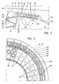
- Fig. 2 ein vergrösserter Ausschnitt der Primärzone der Brennkammer;
- Fig. 3 einen Teilquerschnitt durch die Primärzone der Brennkammer nach Linie 3-3 in Fig. 2;
- Es sind nur die für das Verständnis der Erfindung wesentlichen Elemente gezeigt. Nicht dargestellt sind von der Anlage beispielsweise das vollständige Abgasrohr mit Kamin sowie die Eintrittspartien des Verdichterteils. Die Strömungsrichtung der Arbeitsmittel ist mit Pfeilen bezeichnet.
- Die Anlage, von der in Fig. 1 nur die oberhalb der Maschinenachse 10 liegende Hälfte dargestellt ist, besteht gasturbinenseitig (1) im wesentlichen aus dem mit Laufschaufeln beschaufelten Rotor 11 und dem mit Leitschaufeln bestückten Schaufelträger 12. Der Schaufelträger 12 ist über Vorsprünge in entsprechenden Aufnahmen im Turbinengehäuse 13 eingehängt. An das Turbinengehäuse 13 ist das Abgasgehäuse 14 angeflanscht, welches im wesentlichen aus einem nabenseitigen, ringförmigen Innenteil 16 und einem ringförmigen Aussenteil 17 besteht, welche den Diffusor 19 begrenzen. Beide Elemente 16 und 17 sind in der Regel Halbschalen mit axialer Trennebene. Sie sind miteinander verbunden durch mehrere radiale Strömungsrippen 18, die gleichmässig verteilt über den Umfang angeordnet sind. Im Hohlraum innerhalb des Innenteils 16 ist die austrittsseitige Lagerung der Turbomaschine angeordnet, wobei der Rotor 11 in einem Traglager 21 einliegt.
- Das Turbinengehäuse 13 und der Schaufelträger 12 sind mit einer in der Maschinenachse 10 liegenden, nicht dargestellten, horizontalen Trennebene versehen. Darin sind die in der Regel mit Flanschen versehenen oberen und unteren Hälften des Turbinengehäuses und des Schaufelträgers miteinander verschraubt.
- Im dargestellten Fall umfasst das Turbinengehäuse 13 ebenfalls den Sammelraum 15 für die verdichtete Brennluft. Aus diesem Sammelraum gelangt ein Teil der Brennluft in die Ringbrennkammer 3, welche ihrerseits in den Turbineneinlass, d.h. stromaufwärts der ersten Leitreihe mündet. In den Sammelraum gelangt die verdichtete Luft aus dem Diffusor 22 des Verdichters 2. Von letzterem sind lediglich die drei letzten Stufen dargestellt. Die Laufbeschaufelung des Verdichters und der Turbine sitzen auf der gemeinsamen Welle 11, Deren Mittelachse stellt die Längsachse 10 der Gasturbineneinheit dar.
- Der zwischen Turbine und Verdichter befindliche Wellenteil ist als Trommel 23 ausgebildet. Diese Trommel ist in ihrer ganzen axialen Erstreckung von einer Trommelabdeckung 24 umgeben, welche über nichtdargestellte Rippen mit dem Diffusoraussengehäuse des Verdichters befestigt ist. Diese Trommelabdeckung bildet verdichterseitig das Deckband für die Schaufeln der letzten Verdichterleitreihe. Turbinenseitig begrenzt die Trommelabdeckung zusammen mit der Stirnseite des Turbinenrotors einen radial verlaufenden Radseitenraum. Dieser Raum bildet das austrittsseitige Ende eines Ringkanals 25, welcher, ausgehend von der Nabe hinter der letzten Verdichterlaufreihe, zwischen Trommelabdeckung und Trommel verläuft. In diesen Ringkanal wird die gesamte rotorseitige Kühlluft eingeleitet.
- Die Brennkammer 3 ist an ihrem Kopfende mit Vormischbrennern 20 bestückt, wie sie beispielsweise aus der EP-B1-321 809 bekannt sind. Bei einem solchen in Fig. 2 nur schematisch dargestellten Vormischbrenner handelt es sich um einen sogenannte Doppelkegelbrenner. Im wesentlichen besteht er aus zwei hohlen, kegelförmigen Teilkörpern 26, 27 die in Strömungsrichtung ineinandergeschachtelt sind. Dabei sind die jeweiligen Mittelachsen der beiden Teilkörper gegeneinander versetzt. Die benachbarten Wandungen der beiden Teilkörper bilden in deren Längserstreckung tangentiale Schlitze 28 für die Verbrennungsluft, die auf diese Weise in das Brennerinnere gelangt. Dort ist eine Brennstoffdüse 29 für flüssigen Brennstoff angeordnet. Der Brennstoff wird in einem spitzen Winkel in die Hohlkegel eingedüst. Das entstehende kegelige Flüssigbrennstoffprofil wird von der tangential einströmenden Verbrennungsluft umschlossen. In axialer Richtung wird die Konzentration des Brennstoffes fortlaufend infolge der Vermischung mit der Verbrennungsluft abgebaut. Der Brenner kann ebenfalls mit gasförmigem Brennstoff betrieben werden. Hierzu sind im Bereich der tangentialen Schlitze in den Wandungen der beiden Teilkörper in Längsrichtung verteilte Gaseinström- öffnungen vorgesehen. Im Gasbetrieb beginnt die Gemischbildung mit der Verbrennungsluft somit bereits in der Zone der Eintrittsschlitze 28. Es versteht sich, dass auf diese Weise auch ein Mischbetrieb mit beiden Brennstoffarten möglich ist. Am Brenneraustritt stellt sich eine möglichst homogene Brennstoffkonzentration über dem beaufschlagten kreisringförmigen Querschnitt ein. Es entsteht am Brenneraustritt eine definierte kalottenförmige Rückströmzone, an deren Spitze die Zündung erfolgt.
- Ein Teil der verdichteten Brennluft tritt aus dem Sammelraum 15 durch eine gelochte Abdeckung 30 in Pfeilrichtung in die Brenner ein. Anlässlich der Verbrennung erreichen die Verbrennungsgase sehr hohe Temperaturen, was besondere Anforderungen an die zu kühlenden Brennkammerwandungen darstellt. Dies gilt umsomehr, wenn sogenannte Low NOx-Brenner, beispielsweise die hier zugrundegelegten Vormischbrenner zur Anwendung gelangen, welche relativ bescheidene Kühlluftmengen erfordern. Stromabwärts der Brennermündungen erstreckt sich der ringförmige Verbrennungsraum bis zum Turbineneintritt. Er ist sowohl innen als auch aussen begrenzt durch zu kühlende Wandungen, welche in der Regel als selbsttragende Strukturen konzipiert sind.
- Soweit sind Ringbrennkammern für Gasturbinen bekannt.
- Die vorliegende Brennkammer ist mit 72 der genannten Brenner 20 bestückt. Aus Fig. 3, welches einen Viertelkreisausschnitt zeigt, ist deren Anordnung erkennbar. Je zwei Brenner sind radial übereinanderliegend auf einem Frontsegment 31 angeordnet. 36 von diesen aneinanderliegenden Frontsegmenten bilden einen geschlossenen Kreisring, welcher auf diese Art einen Hitzeschild bildet. Die beiden Brenner von benachbarten Frontsegmenten sind jeweils radial versetzt. Dies bedeutet, dass der radial äussere Brenner jedes zweiten Frontsegmentes unmittelbar an die äussere Ringwand der Brennkammer angrenzt, wie dies auch in Fig. 2 erkennbar ist. Die radial inneren Brenner der andern Frontsegmente sind demnach in unmittelbarer Nähe der innernen Ringwand angeordnet. Hieraus ergibt sich eine ungleichmässige thermische Belastung der entsprechenden Ringwände über dem Umfang.
- Das Brennkammerinnere ist nunmehr in zwei Zonen unterteilt, deren Wandungen auf unterschiedliche Art gekühlt werden.
- Eine stromabwärts liegende und in den Turbineneintritt mündende Sekundärzone 32 ist von einem doppelwandigen Flammrohr begrenzt. Es besteht sowohl an seinem Innenring 33 als auch an seinem Aussenring 34 aus einer flanschlosen, geschweissten Blechkonstruktion, welche über nichtgezeigte Distanzstücke zusammengehalten ist. Beide Ringe 33 und 34 sind an ihrem turbinenseitigen Ende offen und bilden dort den Eintritt für die Kühlluft.
- Der Ringraum 35 zwischen der Doppelwand des Aussenringes 34 bezieht die Luft direkt aus dem Sammelraum 15, wie aus Fig. 1 erkennbar ist. Unter Ausübung einer effizienten Konvektionskühlung strömt die Luft im Gegenstrom zur Brennkammerströmung in Richtung Primärzone 36.
- Der Ringraum 37 zwischen der Doppelwand des Innenringes 33 wird mit Luft aus einem Nabendiffusor 38 versorgt. Dieser Nabendiffusor, welcher an den Verdichterdiffusor 22 anschliesst, wird begrenzt einerseits von der Trommelabdeckung 24 und andererseits von einer Ringschale 39. Letztere ist über nicht dargestellte Rippen mit der Trommelabdeckung 24 verbunden. Auch in diesem Ringraum 37 strömt die Luft im Gegenstrom zur Brennkammerströmung in Richtung Primärzone 36.
- Die Kühlung der hochbelasteten Primärzonen-Wandungen wird nun erfindungsgemäss mittels einzeln gekühlter Kühlsegmenten 40 durchgeführt. Diese in Umfangsrichtung und in Axialrichtung aneinandergereihten Kühlsegmente bilden über die ganze axiale Erstreckung der Primärzone 36 deren strömungsbegrenzende Wandung. Die Einzelkühlung hat den Vorteil des geringen Druckabfalls und die Kühlung kann an lolale Bedingungen angepasst werden.
- Die thermisch hochbelasteten Kühlsegmente 40 bestehen aus einer hochwarmfesten Präzisionsgusslegierung. Sie sind in Umfangsrichtung mit je zwei mit Tragzacken versehenen Füssen 42 in entsprechenden Nuten in einer Tragstruktur eingehängt, ähnlich wie beispielsweise Leitschaufelfüsse in Schaufelträgern befestigt sind. Ebenfalls ähnlich wie Schaufelträger besteht diese Tragstruktur, im folgenden Segmentträger 43 genannt, aus zwei gegossenen Halbschalen mit horizontaler Trennebene und nichtgezeigten Pratzen, mit welchen sie im Turbinengehäuse abgestützt ist.
- In axialer Richtung sind auf diese Weise drei solche Kühlsegmente nebeneinander angeordnet (Fig. 2). Die gegenseitige Abdichtung kann auf einfache Art durch Einlegen einer Dichtschnur zwischen zwei benachbarten Füssen erfolgen.
- In Umfangsrichtung entspricht die Anzahl nebeneinandergereihter Kühlsegmente 40 der Anzahl Frontsegmente 31, so dass jedem Frontsegment und dem der Wand nächstliegendem Brenner 20 ein Kühlsegment zugeordnet ist (Fig. 3). Zur Bildung einer geschlossenen Kühlkammer 44 sind die Kühlsegmente in Umfangsrichtung ebenfalls mit radial verlaufenden Wänden 45 ausgerüstet. Anlässlich der Montage werden die Kühlsegmente mit diesen Wänden 45 in Anschlag gebracht. Die Wände dichten mit ihren Stirnseiten gegen die Unterseite des Segmentträgers 43
- An seiner dem Verbrennungsraum abgekehrten Seite, d.h. der Kühlkammer 44 zugekehrten Seite ist jedes Kühlsegment 40 mit einer verippten oder gewellten Oberfläche 41 versehen. Die Rippen verlaufen in Umfangsrichtung (Fig. 2). Damit ist im Prinzip die Strömungsrichtung der Kühlluft innerhalb der Kühlkammer vorgegeben.
- Die Anspeisung eines Kühlsegmentes mit Kühlluft erfolgt über eine radialgerichtete Öffnung 46, welche den Segmentträger 43 durchdringt und den Sammelraum 15 mit einem in Umfangsrichtung liegenden Ende der Kühlkammer 44 verbindet, möglichst nahe an der Wand 45. Am gegenüberliegenden Ende dieser gleichen Kühlkammer befindet sich, ebenfalls möglichst nahe an der dortigen Wand 45 die Auslassöffnung 47 im Segmentträger. Sowohl die Öffnung 46 als auch die Auslassöffnung 47 können entweder Einzelbohrungen oder Langlöcher sein, die sich in Axialrichtung über einen Grossteil der Segmentbreite erstrecken.
- Die Auslassöffnung 47 mündet in einen Kanal 48, der den Segmentträger 43 in seiner ganzen axialen Erstreckung durchdringt und beidseitig offen ist. Turbinenseitig öffnet er gegen den Ringraum 35 zwischen der Doppelwand des Aussenringes 34. Wie in Fig. 2 schematisch angedeutet, ist dieser Aussenring am Segmentträger angeflanscht, wobei die Kontur der Innenwand an die Kontur der Kühlsegmente angepasst ist. Brennerseitig öffnet der Kanal 48 gegen einen Kopfraum 49, welcher von der Abdeckung 30, und den Frontsegmenten 31 begrenzt ist. Die Abdeckung 30 ist ebenfalls am Segmentträger 43 angeflanscht.
- Diese axialen Kanäle 43, von denen je einer einem Segment in Umfangsrichtung zugeordet ist, dienen somit der gemeinsamen Führung der Segment-Kühlluft und der die Sekundärzone beaufschlagenden Kühlluft. Da der gegen die Primärzone gerichtete Austritt des Flammrohres 33, 34 und der Austritt der Kühlsegmente demnach über die Kanäle 48 unmittelbar in den Brennkammereintritt münden, wird die gesamte Kühlluft ohne grossen Druckabfall dem Verbrennungsprozess zugeführt.
- Zur Kühlung der inneren Wandung der Primärzone werden die gleichen Massnahmen getroffen, wie dies in Fig. 3 anhand der Kühlsegmente 40' angedeutet ist.
- Selbstverständlich ist die Erfindung nicht auf das gezeigte und beschriebene Ausfürungsbeispiel bechränkt. Sie könnte genau so gut Anwendung finden bei der Wandkühlung von Brennkammern der Topfbauart.
-
- 1 Gasturbine
- 2 Verdichter
- 3 Brennkammer
- 10 Maschinenachse
- 11 Rotor
- 12 Schaufelträger
- 13 Turbinengehäuse
- 14 Abgasgehäuse
- 15 Sammelraum
- 16 Innenteil vom Abgasgehäuse
- 17 Aussenteil vom Abgasgehäuse
- 18 Strömungsrippe
- 19 Diffusor von 1
- 20 Brenner
- 21 Traglager
- 22 Diffusor von 2
- 23 Trommel
- 24 Trommelabdeckung
- 25 Ringkanal
- 26 Teilkörper von 20
- 27 Teilkörper von 20
- 28 tangentialer Schlitz
- 29 Brennstoffdüse
- 30 Abdeckung
- 31 Frontsegment
- 32 Sekundärzone
- 33 Innenring von 32
- 34 Aussenring von 32
- 35 Ringraum von 34
- 36 Primärzone
- 37 Ringraum von 33
- 38 Nabendiffusor
- 39 Ringschale
- 40, 40' Kühlsegment
- 41 gewellte Oberfläche von 40 42 Fuss
- 43 Segmentträger
- 44 Kühlkammer
- 45 radiale Wand von 40
- 46 Öffnung
- 47 Auslassöffnung
- 48 Kanal
- 49 Kopfraum
Claims (6)
dass in Umfangsrichtung die Anzahl der aneinandergereihten Kühlsegmente (40) und die Anzahl der Frontsegmente (31) ein ganzzahliges Verhältnis bilden.
Priority Applications (3)
| Application Number | Priority Date | Filing Date | Title |
|---|---|---|---|
| DE59208713T DE59208713D1 (de) | 1992-11-09 | 1992-11-09 | Gasturbinen-Brennkammer |
| EP19920119123 EP0597137B1 (de) | 1992-11-09 | 1992-11-09 | Gasturbinen-Brennkammer |
| JP27937293A JP3526895B2 (ja) | 1992-11-09 | 1993-11-09 | ガスタービンの燃焼器 |
Applications Claiming Priority (1)
| Application Number | Priority Date | Filing Date | Title |
|---|---|---|---|
| EP19920119123 EP0597137B1 (de) | 1992-11-09 | 1992-11-09 | Gasturbinen-Brennkammer |
Publications (2)
| Publication Number | Publication Date |
|---|---|
| EP0597137A1 true EP0597137A1 (de) | 1994-05-18 |
| EP0597137B1 EP0597137B1 (de) | 1997-07-16 |
Family
ID=8210217
Family Applications (1)
| Application Number | Title | Priority Date | Filing Date |
|---|---|---|---|
| EP19920119123 Expired - Lifetime EP0597137B1 (de) | 1992-11-09 | 1992-11-09 | Gasturbinen-Brennkammer |
Country Status (3)
| Country | Link |
|---|---|
| EP (1) | EP0597137B1 (de) |
| JP (1) | JP3526895B2 (de) |
| DE (1) | DE59208713D1 (de) |
Cited By (5)
| Publication number | Priority date | Publication date | Assignee | Title |
|---|---|---|---|---|
| WO1998013645A1 (de) * | 1996-09-26 | 1998-04-02 | Siemens Aktiengesellschaft | Hitzeschildkomponente mit kühlfluidrückführung und hitzeschildanordnung für eine heissgasführende komponente |
| WO1999061841A1 (en) * | 1998-05-25 | 1999-12-02 | Asea Brown Boveri Ab | Cooling arrangement for combustion chamber |
| EP0976982A1 (de) | 1998-07-27 | 2000-02-02 | Asea Brown Boveri AG | Verfahren zum Betrieb einer Gasturbinenbrennkammer mit gasförmigem Brennstoff |
| EP1482246A1 (de) * | 2003-05-30 | 2004-12-01 | Siemens Aktiengesellschaft | Brennkammer |
| CN113924444A (zh) * | 2019-06-07 | 2022-01-11 | 赛峰直升机引擎公司 | 制造用于涡轮机的火焰管的方法 |
Families Citing this family (1)
| Publication number | Priority date | Publication date | Assignee | Title |
|---|---|---|---|---|
| DE59907940D1 (de) | 1998-03-10 | 2004-01-15 | Siemens Ag | Brennkammer und verfahren zum betrieb einer brennkammer |
Citations (3)
| Publication number | Priority date | Publication date | Assignee | Title |
|---|---|---|---|---|
| US4012902A (en) * | 1974-03-29 | 1977-03-22 | Phillips Petroleum Company | Method of operating a gas turbine combustor having an independent airstream to remove heat from the primary combustion zone |
| US4288980A (en) * | 1979-06-20 | 1981-09-15 | Brown Boveri Turbomachinery, Inc. | Combustor for use with gas turbines |
| GB2074308A (en) * | 1980-04-02 | 1981-10-28 | United Technologies Corp | Combustor liner construction |
-
1992
- 1992-11-09 EP EP19920119123 patent/EP0597137B1/de not_active Expired - Lifetime
- 1992-11-09 DE DE59208713T patent/DE59208713D1/de not_active Expired - Lifetime
-
1993
- 1993-11-09 JP JP27937293A patent/JP3526895B2/ja not_active Expired - Fee Related
Patent Citations (3)
| Publication number | Priority date | Publication date | Assignee | Title |
|---|---|---|---|---|
| US4012902A (en) * | 1974-03-29 | 1977-03-22 | Phillips Petroleum Company | Method of operating a gas turbine combustor having an independent airstream to remove heat from the primary combustion zone |
| US4288980A (en) * | 1979-06-20 | 1981-09-15 | Brown Boveri Turbomachinery, Inc. | Combustor for use with gas turbines |
| GB2074308A (en) * | 1980-04-02 | 1981-10-28 | United Technologies Corp | Combustor liner construction |
Cited By (8)
| Publication number | Priority date | Publication date | Assignee | Title |
|---|---|---|---|---|
| WO1998013645A1 (de) * | 1996-09-26 | 1998-04-02 | Siemens Aktiengesellschaft | Hitzeschildkomponente mit kühlfluidrückführung und hitzeschildanordnung für eine heissgasführende komponente |
| US6047552A (en) * | 1996-09-26 | 2000-04-11 | Siemens Aktiengesellschaft | Heat-shield component with cooling-fluid return and heat-shield configuration for a component directing hot gas |
| WO1999061841A1 (en) * | 1998-05-25 | 1999-12-02 | Asea Brown Boveri Ab | Cooling arrangement for combustion chamber |
| EP0976982A1 (de) | 1998-07-27 | 2000-02-02 | Asea Brown Boveri AG | Verfahren zum Betrieb einer Gasturbinenbrennkammer mit gasförmigem Brennstoff |
| EP1482246A1 (de) * | 2003-05-30 | 2004-12-01 | Siemens Aktiengesellschaft | Brennkammer |
| WO2004106809A1 (de) * | 2003-05-30 | 2004-12-09 | Siemens Aktiengesellschaft | Brennkammer |
| US8245513B2 (en) | 2003-05-30 | 2012-08-21 | Siemens Aktiengesellschaft | Combustion chamber |
| CN113924444A (zh) * | 2019-06-07 | 2022-01-11 | 赛峰直升机引擎公司 | 制造用于涡轮机的火焰管的方法 |
Also Published As
| Publication number | Publication date |
|---|---|
| EP0597137B1 (de) | 1997-07-16 |
| JPH06213458A (ja) | 1994-08-02 |
| JP3526895B2 (ja) | 2004-05-17 |
| DE59208713D1 (de) | 1997-08-21 |
Similar Documents
| Publication | Publication Date | Title |
|---|---|---|
| EP0597138B1 (de) | Gasturbinen-Brennkammer | |
| DE60031744T2 (de) | Turbinenbrennkammeranordnung | |
| DE102011000587B4 (de) | Systeme und Verfahren zur Zufuhr von Hochdruckluft zum Kopfende einer Brennkammer | |
| DE60310170T2 (de) | Brennstoffinjektionsvorrichtung | |
| EP0781967B1 (de) | Gasturbinenringbrennkammer | |
| EP0059490B1 (de) | Ringbrennkammer mit Ringbrenner für Gasturbinen | |
| DE3007763C2 (de) | Ringbrennkammer für Gasturbinentriebwerke | |
| EP2808611B1 (de) | Injektor zum Einbringen eines Brennstoff-Luft-Gemisches in eine Brennkammer | |
| DE102005048815A1 (de) | Kostengünstige Zweibrennstoffbrennkammer und zugehöriges Verfahren | |
| DE112017002155B4 (de) | Gasturbine | |
| DE112013007579B4 (de) | Flüssigbrennstoffpatrone für eine Brennstoffdüse und Brennstoffdüse | |
| DE102008002931A1 (de) | Vorrichtung/Verfahren zur Kühlung einer Brennkammer/Venturi-Düse in einem Brenner mit niedrigen NOx-Emissionen | |
| CH703765B1 (de) | Düse und Verfahren zum Mischen von Brennstoff und Luft in einer Gasturbinendüse. | |
| DE102015112767A1 (de) | Brennstoffinjektoranordnungen in Verbrennungsturbinen | |
| DE2507182A1 (de) | Axialgasturbinenanlage | |
| DE3602644C2 (de) | ||
| CH702575B1 (de) | Kraftstoffdüse und Gasturbinenmotor. | |
| EP0489193B1 (de) | Gasturbinen-Brennkammer | |
| CH697920A2 (de) | Turbinentriebwerk mit einer Brennkammerauskleidung mit wirbelluftgekühltem hinterem Ende und Kühlverfahren. | |
| CH701961A2 (de) | Strömungsmaschine. | |
| DE102016106491A1 (de) | Brennstoffdüsenanordnung mit einer Pilotdüse | |
| EP2182285A1 (de) | Brennereinsatz für eine Gasturbinenbrennkammer und Gasturbine | |
| DE2013249A1 (de) | Verbrennungseinrichtung für Gasturbinenstrahltriebwerke | |
| DE2116429A1 (de) | Brennkammer fur Gasturbinenmaschinen | |
| DE2422362B2 (de) | Ringbrennkammer für ein Gasturbinentriebwerk |
Legal Events
| Date | Code | Title | Description |
|---|---|---|---|
| PUAI | Public reference made under article 153(3) epc to a published international application that has entered the european phase |
Free format text: ORIGINAL CODE: 0009012 |
|
| AK | Designated contracting states |
Kind code of ref document: A1 Designated state(s): DE FR GB IT NL |
|
| RBV | Designated contracting states (corrected) |
Designated state(s): DE FR GB IT NL |
|
| RIN1 | Information on inventor provided before grant (corrected) |
Inventor name: TSCHIRREN, STEFAN Inventor name: KELLER, ALBERT |
|
| 17P | Request for examination filed |
Effective date: 19941031 |
|
| 17Q | First examination report despatched |
Effective date: 19951201 |
|
| GRAG | Despatch of communication of intention to grant |
Free format text: ORIGINAL CODE: EPIDOS AGRA |
|
| GRAH | Despatch of communication of intention to grant a patent |
Free format text: ORIGINAL CODE: EPIDOS IGRA |
|
| GRAH | Despatch of communication of intention to grant a patent |
Free format text: ORIGINAL CODE: EPIDOS IGRA |
|
| GRAA | (expected) grant |
Free format text: ORIGINAL CODE: 0009210 |
|
| AK | Designated contracting states |
Kind code of ref document: B1 Designated state(s): DE FR GB IT NL |
|
| PG25 | Lapsed in a contracting state [announced via postgrant information from national office to epo] |
Ref country code: IT Free format text: LAPSE BECAUSE OF FAILURE TO SUBMIT A TRANSLATION OF THE DESCRIPTION OR TO PAY THE FEE WITHIN THE PRE;WARNING: LAPSES OF ITALIAN PATENTS WITH EFFECTIVE DATE BEFORE 2007 MAY HAVE OCCURRED AT ANY TIME BEFORE 2007. THE CORRECT EFFECTIVE DATE MAY BE DIFFERENT FROM THE ONE RECORDED.SCRIBED TIME-LIMIT Effective date: 19970716 Ref country code: NL Free format text: LAPSE BECAUSE OF FAILURE TO SUBMIT A TRANSLATION OF THE DESCRIPTION OR TO PAY THE FEE WITHIN THE PRESCRIBED TIME-LIMIT Effective date: 19970716 |
|
| RAP1 | Party data changed (applicant data changed or rights of an application transferred) |
Owner name: ASEA BROWN BOVERI AG |
|
| REF | Corresponds to: |
Ref document number: 59208713 Country of ref document: DE Date of ref document: 19970821 |
|
| GBT | Gb: translation of ep patent filed (gb section 77(6)(a)/1977) |
Effective date: 19970919 |
|
| ET | Fr: translation filed | ||
| NLV1 | Nl: lapsed or annulled due to failure to fulfill the requirements of art. 29p and 29m of the patents act | ||
| PLBE | No opposition filed within time limit |
Free format text: ORIGINAL CODE: 0009261 |
|
| STAA | Information on the status of an ep patent application or granted ep patent |
Free format text: STATUS: NO OPPOSITION FILED WITHIN TIME LIMIT |
|
| 26N | No opposition filed | ||
| REG | Reference to a national code |
Ref country code: GB Ref legal event code: IF02 |
|
| REG | Reference to a national code |
Ref country code: GB Ref legal event code: 732E |
|
| REG | Reference to a national code |
Ref country code: FR Ref legal event code: CD Ref country code: FR Ref legal event code: CA |
|
| REG | Reference to a national code |
Ref country code: FR Ref legal event code: TP |
|
| PGFP | Annual fee paid to national office [announced via postgrant information from national office to epo] |
Ref country code: FR Payment date: 20101109 Year of fee payment: 19 |
|
| PGFP | Annual fee paid to national office [announced via postgrant information from national office to epo] |
Ref country code: DE Payment date: 20101130 Year of fee payment: 19 |
|
| PGFP | Annual fee paid to national office [announced via postgrant information from national office to epo] |
Ref country code: GB Payment date: 20101022 Year of fee payment: 19 |
|
| PG25 | Lapsed in a contracting state [announced via postgrant information from national office to epo] |
Ref country code: DE Free format text: LAPSE BECAUSE OF THE APPLICANT RENOUNCES Effective date: 20101102 |
|
| GBPC | Gb: european patent ceased through non-payment of renewal fee |
Effective date: 20111109 |
|
| REG | Reference to a national code |
Ref country code: FR Ref legal event code: ST Effective date: 20120731 |
|
| PG25 | Lapsed in a contracting state [announced via postgrant information from national office to epo] |
Ref country code: GB Free format text: LAPSE BECAUSE OF NON-PAYMENT OF DUE FEES Effective date: 20111109 |
|
| PG25 | Lapsed in a contracting state [announced via postgrant information from national office to epo] |
Ref country code: FR Free format text: LAPSE BECAUSE OF NON-PAYMENT OF DUE FEES Effective date: 20111130 |