EP0597201A1 - Vorrichtung und Verfahren zur Reduzierung von Geräuschen in einem Vollduplexlautfernsprecher oder dergleichen - Google Patents
Vorrichtung und Verfahren zur Reduzierung von Geräuschen in einem Vollduplexlautfernsprecher oder dergleichen Download PDFInfo
- Publication number
- EP0597201A1 EP0597201A1 EP93113639A EP93113639A EP0597201A1 EP 0597201 A1 EP0597201 A1 EP 0597201A1 EP 93113639 A EP93113639 A EP 93113639A EP 93113639 A EP93113639 A EP 93113639A EP 0597201 A1 EP0597201 A1 EP 0597201A1
- Authority
- EP
- European Patent Office
- Prior art keywords
- afir
- filter
- microphone
- coefficients
- microphones
- Prior art date
- Legal status (The legal status is an assumption and is not a legal conclusion. Google has not performed a legal analysis and makes no representation as to the accuracy of the status listed.)
- Ceased
Links
Images

Classifications
-
- H—ELECTRICITY
- H04—ELECTRIC COMMUNICATION TECHNIQUE
- H04M—TELEPHONIC COMMUNICATION
- H04M9/00—Arrangements for interconnection not involving centralised switching
-
- H—ELECTRICITY
- H04—ELECTRIC COMMUNICATION TECHNIQUE
- H04M—TELEPHONIC COMMUNICATION
- H04M9/00—Arrangements for interconnection not involving centralised switching
- H04M9/08—Two-way loud-speaking telephone systems with means for conditioning the signal, e.g. for suppressing echoes for one or both directions of traffic
- H04M9/082—Two-way loud-speaking telephone systems with means for conditioning the signal, e.g. for suppressing echoes for one or both directions of traffic using echo cancellers
Definitions
- This invention relates generally to signal processing systems, and more particularly, to signal processing systems for a full-duplex speakerphone or the like.
- the signal processor typically uses an adaptive finite impulse response (AFIR) filter whose coefficients are weighted in accordance with the room acoustics. Each AFIR filter coefficient is multiplied by an audio input signal sample which is delayed by a predetermined number of samples from the current input signal sample. For example if the room causes an echo 50 milliseconds (ms.) after an input signal, the AFIR filter coefficients for samples delayed by 50 ms. are set to cancel this echo. Thus, the signal processor is able to cancel out the echo.
- AFIR adaptive finite impulse response
- full-duplex speakerphones using present signal processing technology have noise problems.
- One problem is that the echo cancellation process produces noise during operation. Since echoes may be generated up to several hundred ms. after the input signal for some environments, full-duplex speakerphones typically must implement very large AFIR filters. For example, full-duplex speakerphones typically require approximately 1000 AFIR filter taps for small rooms. More-complex speakerphone systems, such as teleconferencing systems for larger rooms having multiple microphones and speakers, may require as many as 4000 taps. Since the speakerphones must be able to operate in a variety of environments, they are designed to accommodate environments having high levels of echo. However, noise increases as the numbers of taps increases, resulting in unnecessary noise increases for small room environments.
- initialization noise is more acute for complex systems such as teleconferencing systems.
- the system Before normal operation, the system must initialize the AFIR filter coefficients according to the room acoustics to determine all echo paths. After initialization, the coefficients may be continuously updated.
- a typical teleconferencing system requires five to twenty seconds of initialization upon power up.
- the loudspeakers broadcast noise, typically white noise, in order to measure the echo characteristics.
- Another technique generates a chirp signal instead of white noise.
- the signal processor generates the chirp by rapidly sweeping all the way from a very low frequency to the Nyquist frequency. Either type of initialization is very annoying to users.
- the user cannot keep the system continually operational because the adaptive echo cancellation filter coefficients diverge from optimum during long periods of silence.
- an apparatus for noise reduction for a full-duplex speakerphone or the like comprising a summing device, a delay buffer, and an adaptive finite impulse response (AFIR) filter.
- the summing device has a positive input for receiving a microphone input signal, a negative input, and an output for providing an output signal.
- the delay buffer has an input for receiving a loudspeaker output signal, and an output.
- the AFIR filter has a signal input coupled to the output of the delay buffer, a coefficient input coupled to the output of the summing device, and an output coupled to the negative input of the summing device.
- the delay buffer delays the loudspeaker output signal by a first predetermined number of sample periods.
- the first predetermined number of sample periods is equal to a number of sample periods from a test loudspeaker output signal to a first time period when a power of the digital microphone input signal exceeds a first predetermined threshold.
- the AFIR filter has a number of coefficients equal to a number of sample periods between the first time period and a second time period at which an expected power of the microphone input signal drops below a second predetermined threshold. The apparatus thereby reduces noise in the output signal and has reduced cost.
- a test output signal is provided through a loudspeaker of the full-duplex speakerphone at a first sample point.
- An input from a microphone of the full-duplex speakerphone is sampled at a predetermined frequency for a predetermined number of samples.
- a first number of samples between the first sample point and a second sample point is counted.
- the second sample point occurs when a power of the sampled input signal is greater than a first predetermined threshold.
- a second number of samples between the first sample point and a third sample point is counted.
- the third sample point occurs when an expected power of the sampled input signal is less than a predetermined threshold.
- the sampled input signal is continuously filtered after the predetermined number of samples with an adaptive finite impulse response (AFIR) filter.
- the AFIR filter delays an output signal by the first number.
- the AFIR filter has the second number of taps.
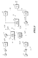
- FIG. 1 illustrates in partial block diagram and partial schematic form a signal processing system 23 for a full-duplex speakerphone 20 or the like in accordance with the present invention.
- FIG. 1 illustrates the various sources of echo encountered by such a system.
- Full-duplex speakerphone 20 includes a microphone 21 and a loudspeaker 22 physically located within a room 30 and each coupled to a speakerphone signal processing system 23.
- Speakerphone signal processing system 23 forms the remainder of the speakerphone and is connected to a near-end four-wire transmission line including a two-wire transmit interface 40 and a two-wire receive interface 41.
- the near-end four-wire transmission line in turn is connected to two-wire transmission line 43 via a transmission line coupler ("TLC") 42.
- TLC transmission line coupler
- Another TLC 44 connects the other end of two-wire transmission line 43 to a far-end four-wire transmission line which includes a two-wire transmit interface 45 and a two-wire receive interface 46.
- Full-duplex speakerphone 20 encounters two types of echo.
- the first type known as electrical echo
- a first echo 50 generated by TLC 42
- a second echo 51 generated by TLC 44
- Each electrical echo returns very quickly to speakerphone 20 and thus signal processing system 23 need only implement AFIR filters having relatively small numbers of taps to cancel these echoes.
- a second type of echo is acoustic echo.
- Acoustic echo is generated by the room acoustics as the sound echoes off physical objects such as walls.
- Acoustic echo differs from electrical echo in that there are multiple echo paths. In room 30, four echo paths 31-34 are illustrated, but many more echo paths are generated.
- Echo path 31 known as the "first attack” path, represents the shortest distance from loudspeaker 22 to microphone 21.
- Acoustic echo also differs from electrical echo because its duration is much longer. Depending on such factors as room size and building materials, an acoustic echo may not dissipate for 300 ms. or longer. Thus, larger AFIR filters are required for acoustic echo cancellation than for electrical echo cancellation.
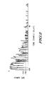
- FIG. 2 illustrates a time-domain power plot for the acoustic echo received by the speakerphone of FIG. 1.
- the horizontal axis represents time measured in sample periods, and the vertical axis represents power measured in decibels (dB).
- Time 0 represents an acoustic stimulus such as a voice spoken in the room or a test signal.
- the microphone receives the first attack.
- the first attack represents the point in time at which the echo exceeds a first threshold labelled "-TH1 " dB.
- the power in the acoustic signal received by microphone 21 varies in response to the various echo paths in the room.
- the acoustical signal dies out, until at a time represented by "N2" sample periods, the acoustical signal falls below a second threshold labelled "-TH2" dB.
- a second threshold labelled "-TH2" dB.
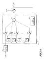
- FIG. 3 illustrates in partial block diagram and partial schematic diagram form signal processing system 23 of FIG. 1.
- FIG. 3 also illustrates microphone 21, loudspeaker 22, interfaces 40 and 41, TLC 42, and two-wire transmission line 43.
- Signal processing system 23 includes generally an amplifier 60, an analog-to-digital converter (ADC) 61, an acoustic echo canceller 62, a digital-to-analog converter (DAC) 63, an ADC 64, an electrical echo canceller 65, a DAC 66, and an amplifier 67.
- Amplifier 60 has an input connected to microphone 21, and an output.
- ADC 61 has an input connected to the output of amplifier 60, and an output for providing a signal labelled "y 2 (k)".
- Acoustic echo canceller 62 includes a delay buffer 71, an adaptive finite impulse response (AFIR) filter 72, and a summing device 73.
- Summing device 73 has a positive input connected to the output of ADC 61 for receiving signal y 2 (k), a negative input, and an output for providing a signal labelled "xi (k)".
- DAC 63 has an input connected to the output of summing device 73 for receiving signal X1 (k), and an output connected to interface 40.
- ADC 64 has an input connected to interface 41, and an output for providing a signal labelled "yi (k)”.
- Electrical echo canceller 65 includes an AFIR filter 74, and a summing device 75.
- Summing device 75 has a positive input connected to the output of ADC 64 for receiving signal y, (k), a negative input, and an output for providing a signal labeled "x 2 (k)".
- DAC 66 has an input connected to the output of summing device 75, and an output.
- Amplifier 67 has an input connected to the output of DAC 66, and an output connected to loudspeaker 22. Note that the blocks in FIG. 3 encompass conventional features associated with telephone operation which are not specifically identified, such as pulse-code-modulation (PCM), 60 hertz power supply line filtering, and the like.
- PCM pulse-code-modulation
- AFIR filter 74 has a signal input for receiving signal X1 (k), a feedback input connected to the output of summing device 75, and an output connected to a negative input of summing device 75. Since the output of summing device 75 is an error signal, the second input of AFIR filter 74 is designated "e, (k)", but e 1 (k) is the same as signal x 2 (k).
- AFIR filter 74 is a conventional tapped- delay-line FIR filter using the least-mean-square technique for coefficient adjustment and its operation is well known to the art.
- delay buffer 71 is a variable delay buffer which has a signal input for receiving signal x 2 (k), a delay input for receiving a value labelled "DELAY", and an output.
- AFIR filter 72 has a signal input connected to the output of delay buffer 71, a feedback input connected to the output of summing device 62, a number of taps input for receiving a value labeled "N", and an output connected to a negative input of summing device 73. Since the output of summing device 73 is an error signal, the second input of AFIR filter 74 is designated "e2(k)", but is the same as signal x 1 , (k).
- AFIR filter 72 To accommodate large rooms with poor acoustics, it is desirable for AFIR filter 72 to have a large number of coefficients. However, increasing the number of coefficients for large room sizes also increases the noise for small rooms with good acoustics. This increased noise may be seen by describing the operation of AFIR filter 72 mathematically.
- the output of echo canceller 62 at the output terminal of summing device 73 is expressed as
- Coefficients hj(k) are updated every sample period to minimize error signal e2(k) according to the least-mean-squares (LMS) method.
- LMS least-mean-squares
- the LMS method which is one implementation of the steepest descent method, updates coefficient vector H(k) at each sample point k according to the following relation: where K denotes the loop gain factor (convergence parameter).
- the LMS adaptive method forces the error term to zero. When the error terms are minimized, the adaptive filter impulse response is said to have converged to the impulse response of the echo path.
- AFIR filter 72 continuously finds a Wiener solution in the time domain recursively as expressed below: where W represents the coefficient vector, R x y(k) represents the cross-correlation vector between the received signal x(k) and the echo signal y(k), and R xx (k) represents the autocorrelation matrix of the received signal x(k) at time k.
- W represents the coefficient vector
- R x y(k) represents the cross-correlation vector between the received signal x(k) and the echo signal y(k)
- R xx (k) represents the autocorrelation matrix of the received signal x(k) at time k.
- the inverse matrix (R xx (k))- 1 must be computed. If the number of coefficients is too large in relation to the time the echo dies out, then R xx - 1 is a sparse matrix with many zeros or with small numbers located on the diagonal. Such a matrix cannot be inverted in a strict mathematical sense. Thus, inaccuracie
- DELAY is set to N1, where N1 represents the number of samples between an acoustic signal and the first attack in which the echo of the acoustic signal exceeds a first threshold of -TH1 as previously illustrated in FIG. 2.
- N is set to (N2 - N1), where N2 represents the number of samples it takes for the echoes of an acoustic signal to fall below a second threshold -TH2 as previously illustrated in FIG. 2.
- the values DELAY and N are determined by measuring the acoustical properties of the room at initialization.
- One possible initialization sequence proceeds as follows. First, signal processing system 23 provides a unit pulse to loudspeaker 22 via DAC 66. Second, the output clock for DAC 66 is synchronized to the input clock for ADC 61. Third, signal processing system 23 collects a predetermined number of samples with which to measure the acoustical echo characteristics. This predetermined number should be large enough to accommodate any room size. After the samples are collected, signal processing system 23 measures the number of samples between the start of the acoustical signal and the first attack (N1), and provides this value as DELAY to delay buffer 73. Signal processing system 23 also measures the number of samples between the first attack and the sample in which the echo falls below -TH2 (N2 - N1) and provides this value as N to AFIR filter 74. At that point, normal operation is possible.
- Signal processing system 23 may be implemented using conventional integrated circuits such as the Motorola DSP56001 General-Purpose Digital Signal Processor and conventional ADCs and DACs.
- Each of AFIR filters 70 and 74 may be implemented by conventional integrated circuits such as by using one or more Motorola DSP56200 Cascadable-Adaptive Finite-Impulse-Response (CAFIR) Digital Filter Chips.
- CAFIR Cascadable-Adaptive Finite-Impulse-Response
- a software routine running on the general-purpose digital signal processor performs the initialization. For example, TABLE I represents a DSP56001 instruction-set sequence which collects 8000 samples:
- FIG. 4 illustrates a detailed block diagram of a digital signal processing representation of acoustic echo canceller 62 of FIG. 3.
- Delay buffer 71 delays signal x 2 (k) by a number of sample periods equal to DELAY and corresponding to the measured first attack.
- the output of delay buffer 71 is passed sequentially through delay elements in AFIR filter 72 labelled "z-1".
- FIG. 4 illustrates four representative delay elements 80, 81, 82, and 83.
- Delay element 80 has an input for receiving the output of delay buffer 71, and an output;
- delay element 81 has an input for receiving the output of delay element 80, and an output; and so on.
- AFIR filter 72 includes a total of (N - 1) delay elements but additional delay elements are not shown in FIG. 4.
- AFIR filter 74 also includes a total of N variable multipliers which multiply samples having varying delays by respective filter coefficients.
- a first variable multiplier 90 multiplies the output of delay buffer 73 by a coefficient labelled "h o "; a second variable multiplier 91 multiplies the output of delay element 80 by a coefficient labeled "h 1 "; a third variable multiplier 92 multiplies the output of delay element 81 by a coefficient labelled "h2"; and so on until a last delay element 94 multiplies the output of delay element 84 by a coefficient labelled "h N - 1 ".
- the outputs of each variable multiplier are summed at positive input terminals of a summing device 95.
- Summing device 95 has an output connected to a subtract input of summing device 73. The output of summing device 95 is thus subtracted from signal y 2 (k) to provide error signal e2(k).
- a least-mean-squared (LMS) predictor 96 receives signal e2(k) and adjusts each filter coefficient h j of respective variable multipliers in order to minimize e2(k).
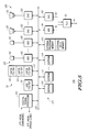
- FIG. 5 illustrates in block diagram form a data processing system 100 for implementing the signal processing system of FIG. 2 in a multi-microphone environment.
- Data processing system 100 includes generally a general-purpose digital signal processor 101, a communications bus 102, a memory 103, a nonvolatile memory portion 104, a microphone portion 105, and a loudspeaker portion 106.
- Digital signal processor 101 has an input for receiving an "OFF-HOOK" indication from speakerphone hardware (not shown), and an output for providing the OFF-HOOK indication to the phone line.
- Digital signal processor 101 is connected to communications bus 102 for conducting address, data, and control signals to and from various devices in data processing system 100.
- One such device is memory 103, which includes an external program memory and an external data memory.
- Nonvolatile memory portion 104 includes at least one electrically-erasable programmable read only memory (EEPROM) 110.
- EEPROM electrically-erasable programmable read only memory
- nonvolatile memory portion 104 includes additional EEPROMs corresponding to the number of microphones in the system such as illustrative EEPROMs 111 and 114.
- AFIR filter 70 Electrical echo cancellation is performed by an AFIR filter 70 connected to communications bus 102.
- AFIR filter 72 which has many taps to accommodate the speakerphone.
- AFIR filter 72 actually includes three cascadable AFIR (CAFIR) filters such as the DSP56200.
- CAFIR cascadable AFIR
- FIG. 5 illustrates microphone portion 105 as including a variable number of microphones and corresponding ADCs.
- a first microphone 140 is connected to an input of an ADC 142, the output of which is connected to communications bus 102.
- a second microphone 141 is connected to an input of an ADC 143, the output of which is connected to communications bus 102.
- FIG. 5 illustrates loudspeaker portion 106 as including a variable number of loudspeakers and corresponding DACs.
- a first loudspeaker 130 is connected to an output of a DAC 132, an input of which is connected to communications bus 102.
- a second loudspeaker 131 is connected to an output of a DAC 133, an input of which is connected to communications bus 102.
- Data processing system 100 avoids the annoying 5-20 seconds of noise encountered on each initialization of known teleconferencing systems.
- DSP 101 performs a conventional pink-noise initialization, measuring the echo generated thereby with the corresponding microphone. However, the filter coefficient values are then saved to EEPROM 110.
- EEPROM 110 Upon detection of OFF-HOOK (HARDWARE), DSP 101 transfers the filter coefficient values stored in EEPROM 110 to AFIR filter 72. After the values are transferred, DSP 101 activates the OFF-HOOK (PHONE LINE) signal to trigger the telephone line relay. The delay introduced during the coefficient loading is too small to be noticed by the user.
- DSP 101 must sample the input port by which it receives the OFF-HOOK (HARDWARE) signal often enough so that the user will not notice the delay, for example at least once every 100 ms.
- HARDWARE OFF-HOOK
- the coefficient values are constantly updated.
- the coefficient values are transferred from CAFIR filters 120-122 to EEPROM 110 in response to an inactivation of OFF-HOOK (HARDWARE).
- HARDWARE OFF-HOOK
- DSP 101 inactivates OFF-HOOK (PHONE LINE).
- a second sequence is particularly useful for multiple-microphone systems.
- DSP 101 Upon first initializing the system after set up in a new room, DSP 101 performs a pink-noise initialization for each microphone. The filter coefficient values for each microphone are then transferred to additional EEPROMs such as EEPROMS 111 and 114. Filter coefficient values are transferred from an EEPROM to CAFIR filters 120-122 as above in response to OFF-HOOK (HARDWARE).
- software running on DSP 101 implements a system known as adaptive beamforming to determine which microphone to activate. Adaptive beamforming estimates power received from each microphone and selects the microphone having the highest power. When the adaptive beamforming software selects a different microphone, coefficients for the old microphone are dynamically stored in the corresponding EEPROM and replaced by coefficient values from the EEPROM corresponding to the new microphone. A typical replacement takes less than 50 milliseconds.
- the echo canceller delays a signal input to an acoustic echo- cancellation AFIR filter for a length of time equal to the number of sample periods between a test signal and a first attack thereof.
- the echo canceller adaptively adjusts the number of AFIR filter taps used, to equal the number of sample periods between the first attack and a time in which the expected power in the echo falls below a predetermined threshold.
- the signal processing system also reduces initialization noise.
- AFIR filter coefficients are measured in an initialization sequence. These coefficients are stored in a nonvolatile memory and transferred to the AFIR filter in response to an off-hook indication. During operation, the filter coefficients are continuously updated. The coefficients are transferred back to the nonvolatile memory in response to an on-hook indication.
- Second, several nonvolatile memories are used to store corresponding AFIR filter coefficients corresponding to different microphones in a multi-microphone system. During operation, the coefficients corresponding to a new microphone are substituted dynamically for coefficients of an old microphone, using a power-estimating algorithm such as adaptive beamforming. Thus, the annoying initialization noise normally encountered at the beginning of each new call is avoided.
Landscapes
- Engineering & Computer Science (AREA)
- Signal Processing (AREA)
- Cable Transmission Systems, Equalization Of Radio And Reduction Of Echo (AREA)
- Circuit For Audible Band Transducer (AREA)
Priority Applications (1)
| Application Number | Priority Date | Filing Date | Title |
|---|---|---|---|
| EP98103607A EP0854625A2 (de) | 1992-11-12 | 1993-08-26 | Vorrichtung und Verfahren zur Reduzierung von Geräuschen in einem Vollduplexlautfernsprecher oder dergleichen |
Applications Claiming Priority (2)
| Application Number | Priority Date | Filing Date | Title |
|---|---|---|---|
| US07/975,348 US5410595A (en) | 1992-11-12 | 1992-11-12 | Apparatus and method for noise reduction for a full-duplex speakerphone or the like |
| US975348 | 2001-10-11 |
Publications (1)
| Publication Number | Publication Date |
|---|---|
| EP0597201A1 true EP0597201A1 (de) | 1994-05-18 |
Family
ID=25522930
Family Applications (2)
| Application Number | Title | Priority Date | Filing Date |
|---|---|---|---|
| EP93113639A Ceased EP0597201A1 (de) | 1992-11-12 | 1993-08-26 | Vorrichtung und Verfahren zur Reduzierung von Geräuschen in einem Vollduplexlautfernsprecher oder dergleichen |
| EP98103607A Withdrawn EP0854625A2 (de) | 1992-11-12 | 1993-08-26 | Vorrichtung und Verfahren zur Reduzierung von Geräuschen in einem Vollduplexlautfernsprecher oder dergleichen |
Family Applications After (1)
| Application Number | Title | Priority Date | Filing Date |
|---|---|---|---|
| EP98103607A Withdrawn EP0854625A2 (de) | 1992-11-12 | 1993-08-26 | Vorrichtung und Verfahren zur Reduzierung von Geräuschen in einem Vollduplexlautfernsprecher oder dergleichen |
Country Status (4)
| Country | Link |
|---|---|
| US (1) | US5410595A (de) |
| EP (2) | EP0597201A1 (de) |
| JP (1) | JP3280496B2 (de) |
| KR (1) | KR100269836B1 (de) |
Cited By (7)
| Publication number | Priority date | Publication date | Assignee | Title |
|---|---|---|---|---|
| DE4430189A1 (de) * | 1994-08-25 | 1996-02-29 | Sel Alcatel Ag | Verfahren zur adaptiven Echokompensation |
| EP0831478A1 (de) * | 1996-09-24 | 1998-03-25 | Hewlett-Packard Company | Datenverarbeitungsgerät und -verfahren |
| WO1999033323A1 (en) * | 1997-12-19 | 1999-07-01 | Conexant Systems, Inc. | Method and apparatus for multi-way conference calling with a full-duplex speakerphone and a digital wireless communication terface |
| WO2002039709A1 (en) * | 2000-11-07 | 2002-05-16 | Telit Mobile Terminals S.P.A. | Control system of acoustic echo cancellers for telephone terminals with handset or handsfree |
| WO2003092184A1 (en) * | 2002-04-26 | 2003-11-06 | Global Ip Sound Inc | Echo cancellation |
| US7639744B1 (en) | 1999-06-25 | 2009-12-29 | Infineon Technologies Ag | Programmable digital bandpass filter for a codec circuit |
| CN104769670A (zh) * | 2012-09-06 | 2015-07-08 | 萨热姆通信宽带简易股份有限公司 | 用于将参考音频信号提供给声学处理单元的装置和方法 |
Families Citing this family (40)
| Publication number | Priority date | Publication date | Assignee | Title |
|---|---|---|---|---|
| US5386372A (en) * | 1992-03-12 | 1995-01-31 | Honda Giken Kogyo Kabushiki Kaisha | Vibration/noise control system for vehicles |
| US5548638A (en) * | 1992-12-21 | 1996-08-20 | Iwatsu Electric Co., Ltd. | Audio teleconferencing apparatus |
| US6594688B2 (en) * | 1993-10-01 | 2003-07-15 | Collaboration Properties, Inc. | Dedicated echo canceler for a workstation |
| US5689641A (en) * | 1993-10-01 | 1997-11-18 | Vicor, Inc. | Multimedia collaboration system arrangement for routing compressed AV signal through a participant site without decompressing the AV signal |
| US5546459A (en) * | 1993-11-01 | 1996-08-13 | Qualcomm Incorporated | Variable block size adaptation algorithm for noise-robust acoustic echo cancellation |
| US5675644A (en) * | 1995-09-26 | 1997-10-07 | Qualcomm Incorporated | Method and apparatus for canceling echo accounting for delay variations |
| US5933494A (en) * | 1995-12-07 | 1999-08-03 | Rockwell International Corporation | Echo canceling method and apparatus in a communication device |
| KR100197794B1 (ko) * | 1996-05-25 | 1999-06-15 | 최승원 | 무선통신시스템에서 간섭을 최소화하고 잡음의 영향을 줄여주기 위한 신호처리 장치 및 방법 |
| KR100200635B1 (ko) * | 1996-10-28 | 1999-06-15 | 윤종용 | 화상회의 시스템에서의 반향제어 장치 및 제어방법 |
| JPH10136076A (ja) * | 1996-10-29 | 1998-05-22 | Matsushita Electric Ind Co Ltd | 電話装置 |
| US7072476B2 (en) * | 1997-02-18 | 2006-07-04 | Matech, Inc. | Audio headset |
| US7046795B2 (en) * | 1997-06-25 | 2006-05-16 | Intel Corporation | Method and apparatus for active latency characterization |
| FI114422B (fi) * | 1997-09-04 | 2004-10-15 | Nokia Corp | Lähteen puheaktiviteetin tunnistus |
| US6816904B1 (en) * | 1997-11-04 | 2004-11-09 | Collaboration Properties, Inc. | Networked video multimedia storage server environment |
| AU2564999A (en) * | 1998-01-27 | 1999-08-09 | Collaboration Properties, Inc. | Multifunction video communication service device |
| US6381224B1 (en) | 1999-03-31 | 2002-04-30 | Motorola, Inc. | Method and apparatus for controlling a full-duplex communication system |
| US6580795B1 (en) | 1999-10-14 | 2003-06-17 | Motorola, Inc. | Echo canceller for a full-duplex communication system and method therefor |
| US6683859B1 (en) | 1999-11-12 | 2004-01-27 | Motorola, Inc. | Method and apparatus for echo cancellation updates in a multicarrier transceiver system |
| WO2001093554A2 (en) * | 2000-05-26 | 2001-12-06 | Koninklijke Philips Electronics N.V. | Method and device for acoustic echo cancellation combined with adaptive beamforming |
| GB0024350D0 (en) * | 2000-10-05 | 2000-11-22 | Mitel Corp | Use of handset microphone to enhance speakerphone loudspeaker performance |
| JP3693588B2 (ja) * | 2000-11-01 | 2005-09-07 | 富士通株式会社 | エコー抑制システム |
| US20020181699A1 (en) * | 2001-03-23 | 2002-12-05 | Tien Pham | System for convolutional echo cancellation by iterative autocorrelation |
| US7996232B2 (en) * | 2001-12-03 | 2011-08-09 | Rodriguez Arturo A | Recognition of voice-activated commands |
| US6889191B2 (en) | 2001-12-03 | 2005-05-03 | Scientific-Atlanta, Inc. | Systems and methods for TV navigation with compressed voice-activated commands |
| US7826805B2 (en) * | 2003-11-11 | 2010-11-02 | Matech, Inc. | Automatic-switching wireless communication device |
| KR100851286B1 (ko) * | 2003-11-11 | 2008-08-08 | 마테크, 인코포레이티드 | 단일 트랜스듀서를 갖는 쌍방향 통신 장치 |
| US7031461B2 (en) * | 2004-01-12 | 2006-04-18 | Acoustic Technologies, Inc. | Robust adaptive filter for echo cancellation |
| JP4576847B2 (ja) * | 2004-02-26 | 2010-11-10 | 沖電気工業株式会社 | エコーキャンセラ制御装置及び音声通信装置 |
| US8315379B2 (en) * | 2004-11-10 | 2012-11-20 | Matech, Inc. | Single transducer full duplex talking circuit |
| LV13342B (en) * | 2005-05-18 | 2005-10-20 | Real Sound Lab Sia | Method and device for correction of acoustic parameters of electro-acoustic transducers |
| US7970123B2 (en) | 2005-10-20 | 2011-06-28 | Mitel Networks Corporation | Adaptive coupling equalization in beamforming-based communication systems |
| JP5130895B2 (ja) * | 2007-12-13 | 2013-01-30 | ソニー株式会社 | 音声処理装置、音声処理システム、音声処理プログラム及び音声処理方法 |
| US8411847B2 (en) * | 2008-06-10 | 2013-04-02 | Conexant Systems, Inc. | Acoustic echo canceller |
| US8369817B2 (en) * | 2008-08-22 | 2013-02-05 | Stmicroelectronics S.A. | Analog FIR filter |
| JP2010068213A (ja) * | 2008-09-10 | 2010-03-25 | Mitsubishi Electric Corp | エコー消去装置 |
| US8923508B2 (en) | 2012-06-07 | 2014-12-30 | Lsi Corporation | Half-duplex speakerphone echo canceler |
| US9307318B2 (en) | 2013-03-07 | 2016-04-05 | Silicon Laboratories Inc. | Audio processor circuits for acoustic echo cancellation and method therefor |
| JP6295722B2 (ja) * | 2014-02-28 | 2018-03-20 | 沖電気工業株式会社 | エコー抑圧装置、プログラム及び方法 |
| JP7122756B2 (ja) * | 2017-06-12 | 2022-08-22 | 株式会社オーディオテクニカ | 音声信号処理装置と音声信号処理方法と音声信号処理プログラム |
| US10938994B2 (en) * | 2018-06-25 | 2021-03-02 | Cypress Semiconductor Corporation | Beamformer and acoustic echo canceller (AEC) system |
Citations (3)
| Publication number | Priority date | Publication date | Assignee | Title |
|---|---|---|---|---|
| EP0221221A1 (de) * | 1985-10-30 | 1987-05-13 | International Business Machines Corporation | Verfahren zur Bestimmung einer flachen Echopfadverzögerung und dieses Verfahren verwendender Echokompensator |
| WO1988002582A1 (en) * | 1986-10-01 | 1988-04-07 | Racal Data Communications Inc. | Echo canceller with adaptive dynamically positioned taps |
| JPH02298124A (ja) * | 1989-05-12 | 1990-12-10 | Nec Corp | エコーキャンセラ回路 |
Family Cites Families (15)
| Publication number | Priority date | Publication date | Assignee | Title |
|---|---|---|---|---|
| JPS57192447A (en) * | 1981-05-23 | 1982-11-26 | Nippon Steel Chem Co Ltd | Production of pearlescent thermoplastic resin product |
| GB2137049B (en) * | 1983-03-15 | 1986-05-14 | Standard Telephones Cables Ltd | Handsfree telephone |
| US4823382A (en) * | 1986-10-01 | 1989-04-18 | Racal Data Communications Inc. | Echo canceller with dynamically positioned adaptive filter taps |
| US4805215A (en) * | 1986-10-01 | 1989-02-14 | Racal Data Communications Inc. | Adaptive echo canceller with sparse dynamically positioned taps |
| EP0272714B1 (de) * | 1986-11-17 | 1992-06-24 | Alcatel N.V. | Einstellbarer Echokompensator |
| FR2628918B1 (fr) * | 1988-03-15 | 1990-08-10 | France Etat | Dispositif annuleur d'echo a filtrage en sous-bandes de frequence |
| US5062102A (en) * | 1988-12-01 | 1991-10-29 | Nec Corporation | Echo canceller with means for determining filter coefficients from autocorrelation and cross-correlation coefficients |
| US4965822A (en) * | 1989-04-10 | 1990-10-23 | Videotelecom Corp. | Full duplex speakerphone |
| JP2785336B2 (ja) * | 1989-06-13 | 1998-08-13 | 日本電気株式会社 | 音響エコーキャンセラのトレーニング方式 |
| US5224094A (en) * | 1990-04-16 | 1993-06-29 | Motorola, Inc. | Communication system network that includes full duplex conference calling |
| US5276678A (en) * | 1990-06-18 | 1994-01-04 | Intelect, Inc. | Distributed switching and telephone conferencing system |
| JPH04123621A (ja) * | 1990-09-14 | 1992-04-23 | Nippon Telegr & Teleph Corp <Ntt> | 反響消去装置 |
| US5187741A (en) * | 1990-11-30 | 1993-02-16 | At&T Bell Laboratories | Enhanced acoustic calibration procedure for a voice switched speakerphone |
| US5164989A (en) * | 1990-12-11 | 1992-11-17 | Octel Communications Corporation | Echo cancellation methods and apparatus for voice processing systems |
| US5313498A (en) * | 1991-06-13 | 1994-05-17 | Nec Corporation | Method and arrangement of echo elimination in digital telecommunications system |
-
1992
- 1992-11-12 US US07/975,348 patent/US5410595A/en not_active Expired - Lifetime
-
1993
- 1993-08-26 EP EP93113639A patent/EP0597201A1/de not_active Ceased
- 1993-08-26 EP EP98103607A patent/EP0854625A2/de not_active Withdrawn
- 1993-10-15 KR KR1019930021394A patent/KR100269836B1/ko not_active Expired - Lifetime
- 1993-11-05 JP JP30119393A patent/JP3280496B2/ja not_active Expired - Lifetime
Patent Citations (3)
| Publication number | Priority date | Publication date | Assignee | Title |
|---|---|---|---|---|
| EP0221221A1 (de) * | 1985-10-30 | 1987-05-13 | International Business Machines Corporation | Verfahren zur Bestimmung einer flachen Echopfadverzögerung und dieses Verfahren verwendender Echokompensator |
| WO1988002582A1 (en) * | 1986-10-01 | 1988-04-07 | Racal Data Communications Inc. | Echo canceller with adaptive dynamically positioned taps |
| JPH02298124A (ja) * | 1989-05-12 | 1990-12-10 | Nec Corp | エコーキャンセラ回路 |
Non-Patent Citations (3)
| Title |
|---|
| H.OIKAWA ET AL.: "Audio Teleconferencing Set with Multipath Echo Canceller", REVIEW OF THE ELECTRICAL COMMUNICATIONS LABORATORIES, vol. 36, no. 2, March 1988 (1988-03-01), TOKYO, JAPAN, pages 217 - 223, XP002059139 * |
| PATENT ABSTRACTS OF JAPAN vol. 15, no. 82 (E - 1038) 26 February 1991 (1991-02-26) * |
| S. PARK ET AL.: "A Novel Implementation of Acoustic and Electrical Echo Cancellers for a Full-Duplex teleconference Phone", TWENTY-FOURTH ASILOMAR CONFERENCE ON SIGNALS,SYSTEMS & COMPUTERS, vol. 1/2, 5 November 1990 (1990-11-05), PACIFIC GROVE, CALIFORNIA, pages 47 - 51, XP000279999 * |
Cited By (12)
| Publication number | Priority date | Publication date | Assignee | Title |
|---|---|---|---|---|
| DE4430189A1 (de) * | 1994-08-25 | 1996-02-29 | Sel Alcatel Ag | Verfahren zur adaptiven Echokompensation |
| US5570423A (en) * | 1994-08-25 | 1996-10-29 | Alcatel N.V. | Method of providing adaptive echo cancellation |
| EP0831478A1 (de) * | 1996-09-24 | 1998-03-25 | Hewlett-Packard Company | Datenverarbeitungsgerät und -verfahren |
| US6078614A (en) * | 1996-09-24 | 2000-06-20 | Hewlett-Packard Company | Data processing apparatus and methods |
| WO1999033323A1 (en) * | 1997-12-19 | 1999-07-01 | Conexant Systems, Inc. | Method and apparatus for multi-way conference calling with a full-duplex speakerphone and a digital wireless communication terface |
| US7639744B1 (en) | 1999-06-25 | 2009-12-29 | Infineon Technologies Ag | Programmable digital bandpass filter for a codec circuit |
| WO2002039709A1 (en) * | 2000-11-07 | 2002-05-16 | Telit Mobile Terminals S.P.A. | Control system of acoustic echo cancellers for telephone terminals with handset or handsfree |
| WO2003092184A1 (en) * | 2002-04-26 | 2003-11-06 | Global Ip Sound Inc | Echo cancellation |
| US7366118B2 (en) | 2002-04-26 | 2008-04-29 | Global Ip Solutions Inc. | Echo cancellation |
| CN100593287C (zh) * | 2002-04-26 | 2010-03-03 | 环球Ip音响欧洲公司 | 回音消除方法、回音消除器和系统设备 |
| CN104769670A (zh) * | 2012-09-06 | 2015-07-08 | 萨热姆通信宽带简易股份有限公司 | 用于将参考音频信号提供给声学处理单元的装置和方法 |
| EP2893531B1 (de) * | 2012-09-06 | 2018-05-30 | Sagemcom Broadband Sas | Vorrichtung und verfahren zur übertragung eines referenztonsignals an eine akustische verarbeitungseinheit |
Also Published As
| Publication number | Publication date |
|---|---|
| KR100269836B1 (ko) | 2000-10-16 |
| JPH06260972A (ja) | 1994-09-16 |
| US5410595A (en) | 1995-04-25 |
| KR940013283A (ko) | 1994-06-25 |
| EP0854625A2 (de) | 1998-07-22 |
| JP3280496B2 (ja) | 2002-05-13 |
Similar Documents
| Publication | Publication Date | Title |
|---|---|---|
| US5410595A (en) | Apparatus and method for noise reduction for a full-duplex speakerphone or the like | |
| EP1324583B1 (de) | Verfahren zur Verstärkungsregelung zur Kompensation eines akustischen Echos | |
| US5343522A (en) | Adaptive sparse echo canceller using a sub-rate filter for active tap selection | |
| EP0366584B1 (de) | Vollduplex-digitaler Lautfernsprecher | |
| US6904146B2 (en) | Full duplex echo cancelling circuit | |
| US5657384A (en) | Full duplex speakerphone | |
| US5852661A (en) | Adaptive echo cancellation used with echo suppression to reduce short and long duration echoes | |
| US6381224B1 (en) | Method and apparatus for controlling a full-duplex communication system | |
| US8073132B2 (en) | Echo canceler and echo canceling program | |
| EP1287672A2 (de) | Verfahren und gerät zur akustischen echounterdrückung mit adaptiver strahlbildung | |
| EP2101480B1 (de) | Echokompensator und Echokompensationsverfahren | |
| US6580795B1 (en) | Echo canceller for a full-duplex communication system and method therefor | |
| CA2335224C (en) | Acoustic echo canceller | |
| US5875246A (en) | Distributed audio signal processing in a network experiencing transmission delay | |
| US6865270B1 (en) | Echo cancellation method and apparatus | |
| JP3385221B2 (ja) | エコーキャンセラ | |
| WO2003053033A1 (en) | Echo canceller having spectral echo tail estimator | |
| Raghavendran | Implementation of an acoustic echo canceller using matlab | |
| Gay et al. | An introduction to acoustic echo and noise control | |
| Kellermann | Echo cancellation | |
| JPH11331047A (ja) | 圧伸器を有する多重チャネルエコ―消去装置 | |
| JPH11122144A (ja) | エコー消去方法および装置 | |
| CA2268096C (en) | Distributed audio signal processing in a network experiencing transmission delay | |
| Jalaputhra et al. | Application of digital signal processing in echo cancellation: A survey | |
| Vaseghi | Echo Cancellation |
Legal Events
| Date | Code | Title | Description |
|---|---|---|---|
| PUAI | Public reference made under article 153(3) epc to a published international application that has entered the european phase |
Free format text: ORIGINAL CODE: 0009012 |
|
| AK | Designated contracting states |
Kind code of ref document: A1 Designated state(s): DE FR GB IT |
|
| 17P | Request for examination filed |
Effective date: 19940801 |
|
| 17Q | First examination report despatched |
Effective date: 19971016 |
|
| GRAG | Despatch of communication of intention to grant |
Free format text: ORIGINAL CODE: EPIDOS AGRA |
|
| 18R | Application refused |
Effective date: 19990102 |