EP0597209B1 - Système optique avec (un) système de lentilles et (une) source de lumière - Google Patents
Système optique avec (un) système de lentilles et (une) source de lumière Download PDFInfo
- Publication number
- EP0597209B1 EP0597209B1 EP93114855A EP93114855A EP0597209B1 EP 0597209 B1 EP0597209 B1 EP 0597209B1 EP 93114855 A EP93114855 A EP 93114855A EP 93114855 A EP93114855 A EP 93114855A EP 0597209 B1 EP0597209 B1 EP 0597209B1
- Authority
- EP
- European Patent Office
- Prior art keywords
- housing
- light source
- lens system
- optical system
- optical
- Prior art date
- Legal status (The legal status is an assumption and is not a legal conclusion. Google has not performed a legal analysis and makes no representation as to the accuracy of the status listed.)
- Expired - Lifetime
Links
Images



Classifications
-
- G—PHYSICS
- G02—OPTICS
- G02B—OPTICAL ELEMENTS, SYSTEMS OR APPARATUS
- G02B6/00—Light guides; Structural details of arrangements comprising light guides and other optical elements, e.g. couplings
- G02B6/24—Coupling light guides
- G02B6/42—Coupling light guides with opto-electronic elements
- G02B6/4201—Packages, e.g. shape, construction, internal or external details
- G02B6/4204—Packages, e.g. shape, construction, internal or external details the coupling comprising intermediate optical elements, e.g. lenses, holograms
Definitions
- the invention relates to an optical system with a lens system in a receptacle, with a light source in a holder, with a spring member between the holder and holder and with a device which determines the position of the light source in the direction of the optical axis of the lens system relative to the latter.
- Such a system is known from DE-OS 31 42 630.
- a semiconductor laser is positioned in a tubular holder in the axial direction of the holder against a stop.
- a spring element is arranged between the lens system and the stop.
- a closure member is arranged on the side of the lens system facing away from the spring member. The lens system is moved in the axial direction against the pressure of the spring member with the aid of the closure member until the semiconductor laser is at the focal point of the lens system. In this position the closure member is fixed to the holder, e.g. welded.
- a version for optical devices is known from EP-A2- 179 426, which permits linear movements in three directions and rotational movements around three axes. It is very time consuming to set a desired position for an optical device with this version.
- the frame is made up of numerous elements and is therefore relatively expensive. The tolerance tolerances are also relatively large in this version.
- a collimator for laser diodes is described in German utility model 90 02 698.
- the laser diode can only be moved in a plane perpendicular to the optical axis.
- the axial adjustment parallel to the optical axis takes place by turning the collimator over a thread and thus moving it in the axial direction.
- a wobble movement occurs here, which causes a corresponding wobble error.
- After fixing the collimator it may be necessary to readjust the laser diode.
- the invention has for its object to provide a system of the type described, in which it is easily possible with a small size and light weight to replace the light source and / or the lens system and in a simple manner a play-free positioning in the axial direction, in particular focusing with great accuracy is possible and with no axial rotation of the light source relative to the lens system.
- the lens system and the light source are each recorded in one receptacle.
- the two receptacles are connected to one another via a holding element and are adjustable relative to one another in the direction of the optical axis.
- At least two dowel pins are provided, which are accommodated on the one hand in the receptacle of the lens system in a press fit and on the other hand in bores in the receptacle for the light source.
- One of the holes is a fitting hole in which the corresponding dowel pin can be moved parallel to the optical axis with a sliding fit.
- a sliding fit is understood to mean a fit with little play.
- the fitting bore and the dowel pin accommodated in it prevent the rotation of the light source holder relative to the optics.
- the radial orientation of the light source relative to the optomechanical system is retained.
- the additional alignment pin prevents the rotation of the light source receptacle around the longitudinal axis of the alignment hole. It limits the backlash or wobble.
- a spring member is arranged between the holder for the light source and the lens system holder.
- the springs which are guided through the dowel pins according to a partial embodiment of the invention, have the function of removing the thread play (backlash) and ensuring a uniform course over the adjustment path.
- the system according to the invention enables play-free positioning in the axial direction with an accuracy that is better than 0.0005 mm. Since the two recordings can be adjusted relative to one another by means of a holding element, the proposed optical system has a focusing area so that the imaging scale can be adjusted: a convergent, afocal and divergent beam exit is thus possible.
- the proposed optical system is small in size and light in weight.
- the light source and lens system components can be replaced at any time, since the two receptacles for these components can be detached from one another and reconnected.
- the lens system can be exchanged in a particularly simple manner if, according to a preferred embodiment of the invention, the dowel pins are not accommodated directly in the receptacle for the lens system, but in a holder which is connected with the receptacle of the lens system in a snug fit.
- a preferred further embodiment of the invention is specified in claim 4.
- another dowel pin is received in an elongated hole in order to be able to compensate for any manufacturing tolerances.
- the further dowel pin can be moved parallel to the optical axis and sits in the slot with a sliding fit.
- a third dowel pin can be provided. This pin does not necessarily have to be designed as a dowel pin, since the task of this pin is merely to form a guide for a third spring and thus jamming is avoided.
- the associated hole in the mount of the lens system can be made too high, since the function is determined with sufficient accuracy by the combination of fits "dowel pin in dowel hole” and "dowel pin in slot”.
- the position of the light source in the installed state is particularly simple, i.e. Axially changeable without tools.
- the function of the dowel pins is divided: on the one hand by shoulder screws, which are anchored in the receptacle for the lens system and are received in bores in the receptacle for the light source, and on the other hand, the receptacle for the lens system takes up the further receptacle for the light source Adjustable in the direction of the optical axis.
- the receptacle for the light source consists of insulating material.
- Such a recording guarantees the potential freedom of the light source and a possibly associated retaining ring compared to the rest of the mechanical-optical combination and thus in particular also relative to the holder of the entire mechanical system.
- the light source of the proposed optical system can in principle be of any type.
- the system is particularly suitable for "point-shaped" light sources, i.e. for light sources with a small radiating area (diameter on the order of a few ⁇ m), e.g. Semiconductor laser diodes.
- a lens system is understood to mean not only a multi-lens system, but also a system consisting of only one lens.
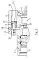
- FIG. 1 shows a section through a preferred exemplary embodiment of the proposed optical system along the optical axis.
- a lens system 1 consisting of several lenses is accommodated in a receptacle 2.
- a semiconductor laser light source 3 is received in a socket 4.
- the version 4 is held in a receptacle 6.
- a holder 7 With the receptacle 2 of the lens system 1, a holder 7 is fitted in a snug fit (reference number 20).
- the holder 7 is screwed onto the receptacle 2 (reference number 21).
- three dowel pins 8a, 8b, 8c (Fig.2) are added.
- the longitudinal axis 12 of the dowel pins 8 are parallel to the optical axis 11 of the lens system. They protrude from the receptacle 2 of the lens system 1.
- the protruding parts of the dowel pins are received in bores 5a, 5b, 5c, which are provided in the receptacle 6 of the laser light source 3.
- the bore 5a is designed as a fitting bore in which a dowel 8a with a sliding fit is seated.
- the dowel pin 8b is received in an elongated hole 5b, the longitudinal axis 14 of which points through the axis of the fitting bore 5a.
- the dowel pin 8b sits in the slot 5b in a sliding fit and prevents rotation of the receptacle 6 about the axis of the fitting bore 5a.
- the fitting hole 5a prevents the rotation of the light source receptacle 6 with respect to the lens system 1.
- the fitting pin 8b in the elongated hole 5b limits the backlash or the wobble error through the combination of fits "5a” - “8a” and "5b” - “8b”.
- the bore 5c is made excessive and only serves to receive the pin 8c.
- Each dowel pin 8 serves as a guide for a spring 9, which is arranged between the receptacle 6 for the laser light source and the holder 7.
- the receptacle 6 for the laser light source 3 has a radial flange 13.
- a ring 10 is connected to the holder 7 via a thread 22. The ring 10 engages behind the flange 13 and thus holds the receptacle 6 for the laser light source on the holder 7 and thus on the receptacle 2 for the lens system 1.
- a holding ring 23 can be screwed onto the receptacle 6 for the laser light source by means of screws 24.
- the retaining ring 23 can also be designed as a heat sink.
- the receptacle 6 for the light source 3 consists of insulating material and thus guarantees the potential freedom between the receptacle 2 for the lens system and the light source.
- the receptacle 6 limits the squint angle to less than 10 mrad and guarantees that the wobble error during translation is much smaller than the squint angle. There is no change in the squint angle during positioning.
- the receptacle 2 for the lens system 1 accommodates the further receptacle 6 for the laser light source 3 in a fit that is adjustable in the direction of the optical axis (reference numeral 25).
- Three shoulder screws 27 are anchored in the receptacle 2 for the lens system.
- the longitudinal axes 15 of the shoulder screws extend essentially parallel to the optical axis 11.
- Bores 16 for receiving the shoulder screw 27 are provided in the receptacle 6 for the laser light source.
- the receptacle 6 for the laser light source 3 and shoulder screw 27 are each axially spring-loaded by means of a spring 9.
- the position of the receptacle 6 for the laser light source 3 is defined by a ring 17.
- Ring 17 is connected via a thread 26 to the receptacle 2 for the lens system.
- a sliding element 18 is arranged, which is connected to the ring 17 or the receptacle 6.
- the receptacle 6 for the laser light source 3 is held on the receptacle 2 for the lens system 1 by means of a ring 19 designed as a differential screw.
- optical system of small size and light weight is described.
- the proposed optical system is also scalable to other sizes.
Landscapes
- Physics & Mathematics (AREA)
- General Physics & Mathematics (AREA)
- Optics & Photonics (AREA)
- Optical Couplings Of Light Guides (AREA)
- Semiconductor Lasers (AREA)
Claims (12)
- Système optique comportant un système (1) de lentilles disposé dans un logement (2), une source de lumière (3) disposée dans une monture (4), un organe (9) à ressort disposé entre la monture et le logement, et un dispositif qui détermine la position de la source de lumière dans la direction de l'axe optique du système de lentilles, par rapport à ce dernier, caractérisé en ce que, dans le logement (2) du système (1) de lentilles sont reçus au moins deux goujons d'assemblage (8) avec ajustage serré, dont les axes longitudinaux (12) sont parallèles à l'axe optique (11) du système (1) de lentille et qui dépassent hors du logement (2) du système (1) de lentilles, en ce que la monture (4) de la source lumineuse (3) est maintenue dans un autre logement (6), dans lequel des perçages (5a, 5b, 5c) sont prévus pour la réception des goujons d'assemblage (8), l'un (5a) des perçages étant un perçage ajusté dans lequel le goujon d'assemblage correspondant (8a) est placé avec ajustement glissant et possibilité d'être déplacé parallèlement à l'axe optique, en ce qu'entre le logement (6) de la source lumineuse (3) et le logement (2) du système (1) de lentilles, un organe respectif à ressort (9) est disposé dans la zone des goujons d'assemblage (8) pour chacun de ceux-ci et en ce que le logement (6) de la source de lumière (3) est maintenu déplaçable et réglable dans la direction de l'axe optique, sur le logement (2) du système (1) de lentilles.
- Système optique selon la revendication 1, caractérisé en ce que les goujons d'assemblage (8) sont reçus dans un dispositif de maintien (7), qui est relié avec ajustement fin au logement (2) du système (1) de lentilles.
- Système optique selon l'une des revendications 1 ou 2, caractérisé en ce les goujons d'assemblage (8) servent de guidage pour l'organe à ressort (9) respectif.
- Système optique selon l'une des revendications 1 à 3, caractérisé en ce que l'un (8b) des goujons d'assemblage est logé dans un trou de section oblongue (5b), dont l'axe longitudinal (14) passe par l'axe du perçage ajusté (5a), ce goujon ajusté (8b) étant monté avec ajustement glissant en pouvant être déplacé, dans le trou long (5b), parallèlement à l'axe optique et empêchant une rotation du logement (6) de la source de lumière (3) sur l'axe du perçage ajusté (5a).
- Système optique selon l'une des revendications 1 à 4, caractérisé en ce que le logement (6) de la source de lumière (3) présente un rebord radial (13) et en ce que ce logement est maintenu contre le logement (2) du système (1) de lentilles ou sur le dispositif de maintien (7), au moyen d'un anneau (10) passant derrière le rebord (13).
- Système optique selon le préambule de la revendication 1, caractérisé en ce que dans le logement (2) du système (1) de lentilles sont ancrées au moins deux vis (27) d'épaulement, dont les axes longitudinaux (15) s'étendent sensiblement parallèlement à l'axe optique (11), en ce que la monture (4) de la source de lumière (3) est maintenue avec ajustement fin et serré dans un autre logement (6), en ce que le logement (2) du système (1) de lentilles reçoit, avec ajustement fin, l'autre logement (6) de la source de lumière (3), de façon réglable dans la direction de l'axe optique (11), en ce que dans le logement (6) de la source de lumière sont prévus des perçages (16) destinés à recevoir les vis (27) à épaulement, en ce qu'entre le logement (6) de la source de lumière (3) et chaque vis (27) à épaulement est disposé un organe à ressort (9) qui s'appuie sur ce logement (6) et sur la vis (27) à épaulement, grâce à quoi le logement (6) de la source lumineuse (3) est maintenu contre le logement (2) du système (1) de lentilles, dans la direction de celui-ci.
- Système optique selon la revendication 6, caractérisé en ce que le logement (6) de la source lumineuse (3) est appuyé sur une bague (17) reliée au logement (2) du système (1) de lentilles.
- Système optique selon la revendication 7, caractérisé en ce que la bague (17) est vissée sur le logement (2) du système (1) de lentilles.
- Système optique selon la revendication 7 ou 8, caractérisé en ce que, dans la zone des surfaces d'appui de la bague (17) et du logement (6), est disposé un élément glissant (18) relié à la bague (17) ou au logement (6).
- Système optique selon la revendication 6, caractérisé en ce que le logement (6) de la source lumineuse (3) est maintenu contre le logement (2) du système (1) de lentilles au moyen d'une bague (19) conformée en vis différentielle.
- Système optique selon l'une des revendications 1 à 10, caractérisé en ce que le logement (6) de la source lumineuse (3) est constitué d'un matériau électriquement isolant.
- Système optique selon l'une des revendications 1 à 11, caractérisé en ce que la source de lumière est un laser à semi-conducteur.
Applications Claiming Priority (2)
| Application Number | Priority Date | Filing Date | Title |
|---|---|---|---|
| DE4237775 | 1992-11-09 | ||
| DE4237775A DE4237775C1 (de) | 1992-11-09 | 1992-11-09 | Optisches System mit einem Linsensystem und einer Lichtquelle |
Publications (2)
| Publication Number | Publication Date |
|---|---|
| EP0597209A1 EP0597209A1 (fr) | 1994-05-18 |
| EP0597209B1 true EP0597209B1 (fr) | 1997-03-26 |
Family
ID=6472433
Family Applications (1)
| Application Number | Title | Priority Date | Filing Date |
|---|---|---|---|
| EP93114855A Expired - Lifetime EP0597209B1 (fr) | 1992-11-09 | 1993-09-15 | Système optique avec (un) système de lentilles et (une) source de lumière |
Country Status (2)
| Country | Link |
|---|---|
| EP (1) | EP0597209B1 (fr) |
| DE (2) | DE4237775C1 (fr) |
Families Citing this family (10)
| Publication number | Priority date | Publication date | Assignee | Title |
|---|---|---|---|---|
| DE19702573C2 (de) * | 1997-01-24 | 2003-11-13 | Sick Ag | Optische Einrichtung mit einer justierbaren Haltevorrichtung |
| EP0911662A3 (fr) * | 1997-09-25 | 2000-01-12 | Siemens Aktiengesellschaft | Dispositif de couplage de la lumière et connecteur optique utilisant ce dispositif |
| DE10026541A1 (de) * | 2000-05-27 | 2001-11-29 | Zeiss Carl | Vorrichtung zur präzisen Positionierung eines Bauteils, insbesondere eines optischen Bauteiles |
| DE10030495A1 (de) | 2000-06-21 | 2002-01-03 | Zeiss Carl | Verfahren zum Verbinden einer Vielzahl von optischen Elementen mit einem Grundkörper |
| DE10331390A1 (de) | 2003-07-11 | 2005-01-27 | Carl Zeiss Smt Ag | Verfahren zur Herstellung von asphärischen optischen Flächen |
| US6816325B1 (en) | 2003-09-11 | 2004-11-09 | Carl Zeiss Smt Ag | Mounting apparatus for an optical element |
| DE102005023972B4 (de) * | 2005-05-20 | 2008-12-04 | Leica Microsystems Cms Gmbh | Mikroskopobjektiv und Mikroskop |
| DE102006000343B3 (de) * | 2006-07-17 | 2007-10-11 | Hilti Ag | Justierbare optische Baugruppe |
| DE102009002779A1 (de) * | 2009-04-30 | 2010-11-04 | Hilti Aktiengesellschaft | Justierbarer Optikträger |
| CN113791472A (zh) * | 2021-11-18 | 2021-12-14 | 之江实验室 | 一种可多维度精密调节的光纤耦合器 |
Family Cites Families (5)
| Publication number | Priority date | Publication date | Assignee | Title |
|---|---|---|---|---|
| NL182031C (nl) * | 1980-11-06 | 1987-12-16 | Philips Nv | Optisch stelsel dat een gekollimeerde lichtbundel levert. |
| US4655548A (en) * | 1984-10-22 | 1987-04-07 | Grumman Aerospace Corporation | Multi-degree of freedom mount |
| JPH01179112A (ja) * | 1988-01-08 | 1989-07-17 | Ricoh Co Ltd | 半導体レーザー装置 |
| US4993801A (en) * | 1989-12-27 | 1991-02-19 | Eastman Kodak Company | Optical head |
| DE9002698U1 (de) * | 1990-03-08 | 1990-05-10 | Schäfter + Kirchhoff, 2000 Hamburg | Kollimator für Laserdioden |
-
1992
- 1992-11-09 DE DE4237775A patent/DE4237775C1/de not_active Expired - Fee Related
-
1993
- 1993-09-15 DE DE59305949T patent/DE59305949D1/de not_active Expired - Fee Related
- 1993-09-15 EP EP93114855A patent/EP0597209B1/fr not_active Expired - Lifetime
Also Published As
| Publication number | Publication date |
|---|---|
| DE59305949D1 (de) | 1997-04-30 |
| EP0597209A1 (fr) | 1994-05-18 |
| DE4237775C1 (de) | 1994-01-20 |
Similar Documents
| Publication | Publication Date | Title |
|---|---|---|
| DE69415762T2 (de) | Vorrichtung zum Regeln der Neigung einer Objektivlinse für optische Abtasteinheit | |
| DE69211327T2 (de) | Justierbare fassung für zylindrische linse | |
| DE3884767T2 (de) | Laserelement. | |
| EP0597209B1 (fr) | Système optique avec (un) système de lentilles et (une) source de lumière | |
| DE2749324A1 (de) | Fokussiervorrichtung fuer optische geraete, insbesondere fuer kameras | |
| DE3650509T2 (de) | Zoom-Mikroskop mit Kurbel und Gestängemechanismus | |
| DE3128190A1 (de) | "laser-halbleitervorrichtung" | |
| DE4013743C2 (fr) | ||
| DE102022200350A1 (de) | Optisches System und Fahrzeug mit wenigstens einem optischen System | |
| DE3613643C1 (de) | Faseroptische Fokusiereinrichtung | |
| DE3413748A1 (de) | Optisches system | |
| EP0660942A1 (fr) | Objectif de microscope pourvu d'une monture de correction | |
| EP1574808B1 (fr) | Lunette de visée | |
| DE69712470T2 (de) | Lasermarkierungs- oder laserperforierungssystem | |
| WO1999040469A1 (fr) | Douille cylindrique destinee a des composant optiques reglables | |
| DE102021107413B3 (de) | Kompakte Justierfassung zur Justierung von zwei optischen Tuben | |
| DE102020134653B3 (de) | Justierbarer Optikhalter für ein optisches Element | |
| EP4168841B1 (fr) | Ensemble optique réglable | |
| DE1797270A1 (de) | Vorrichtung zum Ausrichten von Gegenstaenden | |
| EP0089671B1 (fr) | Dispositif d'ajustage d'un élément optique p.ex. d'un objectif d'un appareil optique | |
| WO2019243016A1 (fr) | Expanseur de faisceau et procédé pour faire fonctionner un expanseur de faisceau | |
| DE3037880C2 (de) | Automatische Fokussiermeßeinrichtung | |
| DE102022214346B3 (de) | Laservorrichtung und Verfahren zu deren Montage | |
| DE4408115B4 (de) | Umlenkspiegelgehäuse für Lasermaterialbearbeitungssysteme | |
| AT517407B1 (de) | Lasereinheit mit Kollimator-Einstellvorrichtung |
Legal Events
| Date | Code | Title | Description |
|---|---|---|---|
| PUAI | Public reference made under article 153(3) epc to a published international application that has entered the european phase |
Free format text: ORIGINAL CODE: 0009012 |
|
| AK | Designated contracting states |
Kind code of ref document: A1 Designated state(s): DE DK FR GB |
|
| 17P | Request for examination filed |
Effective date: 19940617 |
|
| GRAG | Despatch of communication of intention to grant |
Free format text: ORIGINAL CODE: EPIDOS AGRA |
|
| 17Q | First examination report despatched |
Effective date: 19960806 |
|
| GRAH | Despatch of communication of intention to grant a patent |
Free format text: ORIGINAL CODE: EPIDOS IGRA |
|
| GRAH | Despatch of communication of intention to grant a patent |
Free format text: ORIGINAL CODE: EPIDOS IGRA |
|
| GRAA | (expected) grant |
Free format text: ORIGINAL CODE: 0009210 |
|
| AK | Designated contracting states |
Kind code of ref document: B1 Designated state(s): DE DK FR GB |
|
| PG25 | Lapsed in a contracting state [announced via postgrant information from national office to epo] |
Ref country code: FR Effective date: 19970326 Ref country code: DK Effective date: 19970326 |
|
| GBT | Gb: translation of ep patent filed (gb section 77(6)(a)/1977) |
Effective date: 19970327 |
|
| REF | Corresponds to: |
Ref document number: 59305949 Country of ref document: DE Date of ref document: 19970430 |
|
| EN | Fr: translation not filed | ||
| PLBE | No opposition filed within time limit |
Free format text: ORIGINAL CODE: 0009261 |
|
| 26N | No opposition filed | ||
| REG | Reference to a national code |
Ref country code: GB Ref legal event code: 732E |
|
| REG | Reference to a national code |
Ref country code: GB Ref legal event code: IF02 |
|
| PGFP | Annual fee paid to national office [announced via postgrant information from national office to epo] |
Ref country code: DE Payment date: 20020826 Year of fee payment: 10 |
|
| PGFP | Annual fee paid to national office [announced via postgrant information from national office to epo] |
Ref country code: GB Payment date: 20020911 Year of fee payment: 10 |
|
| PG25 | Lapsed in a contracting state [announced via postgrant information from national office to epo] |
Ref country code: GB Free format text: LAPSE BECAUSE OF NON-PAYMENT OF DUE FEES Effective date: 20030915 |
|
| PG25 | Lapsed in a contracting state [announced via postgrant information from national office to epo] |
Ref country code: DE Free format text: LAPSE BECAUSE OF NON-PAYMENT OF DUE FEES Effective date: 20040401 |
|
| GBPC | Gb: european patent ceased through non-payment of renewal fee |
Effective date: 20030915 |