EP0597214A1 - Machine de soudure par points multiples pour le soudage de grilles en fils de fer - Google Patents
Machine de soudure par points multiples pour le soudage de grilles en fils de fer Download PDFInfo
- Publication number
- EP0597214A1 EP0597214A1 EP93115051A EP93115051A EP0597214A1 EP 0597214 A1 EP0597214 A1 EP 0597214A1 EP 93115051 A EP93115051 A EP 93115051A EP 93115051 A EP93115051 A EP 93115051A EP 0597214 A1 EP0597214 A1 EP 0597214A1
- Authority
- EP
- European Patent Office
- Prior art keywords
- welding
- grid
- wire
- contact
- welding machine
- Prior art date
- Legal status (The legal status is an assumption and is not a legal conclusion. Google has not performed a legal analysis and makes no representation as to the accuracy of the status listed.)
- Granted
Links
Images
Classifications
-
- B—PERFORMING OPERATIONS; TRANSPORTING
- B23—MACHINE TOOLS; METAL-WORKING NOT OTHERWISE PROVIDED FOR
- B23K—SOLDERING OR UNSOLDERING; WELDING; CLADDING OR PLATING BY SOLDERING OR WELDING; CUTTING BY APPLYING HEAT LOCALLY, e.g. FLAME CUTTING; WORKING BY LASER BEAM
- B23K11/00—Resistance welding; Severing by resistance heating
- B23K11/002—Resistance welding; Severing by resistance heating specially adapted for particular articles or work
- B23K11/008—Manufacturing of metallic grids or mats by spot welding
Definitions
- the invention relates to a multi-point resistance welding machine for welding wire grids by means of direct current, comprising a contact electrode arrangement for simultaneous contacting of all the grid point of the wire grid belonging to a cross wire to be welded on, and a switching arrangement with a plurality of welding transformers for simultaneous application of welding current to all contacted grid points.
- a resistance welding machine of the type mentioned above is e.g. B. from CH-PS 633 738 known.
- a large number of so-called tab electrodes sit on two busbars running across the entire width of the welding machine. Such a tab electrode is provided for each grid point of the transverse wire to be welded.
- the opposite pressure bar carries a number of current bridges, which each connect two neighboring grid points.
- Direct current resistance welding machines with several spot welding guns are now known, in which the individual welding spots can be monitored individually.
- e.g. B. pointed to the US-PS 5,072,090 or GB 2 249 747.
- the welding points can be welded independently of one another.
- this is only possible in a staggered time, so that even with narrow staggering, an apparently, but not actually, simultaneous welding can be achieved by the different pliers.
- the object of the invention is now to provide a device of the type mentioned at the outset which is also suitable for welding narrow-meshed grids with large wire cross sections.
- the solution is that the contact electrode arrangement has a plurality of welding electrode pairs which contact their respectively assigned grid point from both sides, and that the switching arrangement is designed such that adjacent welding electrode pairs are floating in terms of potential relative to one another.
- Each pair of electrodes is preferably enclosed in a secondary circuit which is not fixed in terms of potential, in each case one welding transformer.
- the only cross connection is the cross wire itself.
- the mutually independent electrode pairs are advantageously matched to a mesh size of the wire grid in a suitable spacing grid such that each grid point to be welded is welded by its own pair of electrodes.
- each grid point to be welded is welded by its own pair of electrodes.
- u In the case of particularly small mesh sizes, u.
- two or more grid points can also be contacted without the effect according to the invention being lost.
- the ratio of the distance between the longitudinal wires (and thus the grid points) to the cross-sectional area of the transverse wire is relevant.
- the spacing grid is typically less than 15 cm, preferably 10 cm or less and 8 cm or less for particularly narrow meshes.
- the minimum spacing grid is determined by the minimum size of the circuit arrangement (in particular the transformers). In most cases, 5, 7.5 and 10 cm should be a good compromise.
- the welding transformers are connected on the primary side to two phases of a three-phase supply network, the connections varying cyclically across the width of the machine.
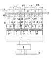
- the single figure schematically shows the circuit arrangement for an inventive device Mesh welding machine shown.
- a cross wire 1 is to be welded with several longitudinal wires 2.1,..., 2.5 perpendicular to it.
- springs or other force generators 4.1.1 / 4.2.1 resp. 4.1.2 / 4.2.2, ... ensure that the longitudinal wires 2.1, ..., 2.5 are pressed well onto the cross wire 1.
- a transformer 3.1, ..., 3.5 with center tap 5.1, ..., 5.5 is provided on the secondary side.
- the center tap 5.1, 5.2, ... is connected to the negative pole, (i.e. the contact electrode 4.2.1, 4.2.2, ).
- the positive pole i.e. the contact electrodes 4.1.1, 4.1.2, ...) is in each case via rectifier elements 6.1, 6.2 or. 6.3, 6.4 or ...., 6.10 (semiconductor diodes) connected to the end taps on the secondary side.
- the welding is therefore carried out with rectified current.
- the transformers 3.1, ..., 3.5 are connected to an inverter switching arrangement 7. This, in turn, is connected to a rectifier circuit 8. The power is supplied by a three-phase network 9.
- the individual contact electrode pairs are not fixed in terms of potential relative to one another, but rather are floating.
- the cross wire 1 then represents the only cross connection.
- the width of the individual contact electrodes 4.1.1, ..., 4.1.5, 4.2.1, ..., 4.2.5 is in any case somewhat less than the distance between adjacent longitudinal wires z . B. 2.1, 2.2. Widths of less than 10 cm are preferred.
- the invention is particularly effective at widths of 7.5 or even 5 cm. In the case of even smaller mesh sizes, technical obstacles are to be expected (generation of high welding currents in confined spaces), but this does not call the principle of the invention into question. With very small mesh sizes, u. U. can be accepted if a pair of welding electrodes contacts two or more grid points simultaneously.
- the individual contact electrodes are preferably rather narrow and are arranged to be laterally displaceable on a supporting structure. This makes it possible (e.g. by loosening the fixing screws) to adjust the mesh welding machine to various mesh sizes with little effort.
- the inverter switching arrangement 7 supplies all the transformers 3.1,..., 3.5 with current at the same time, but preferably enables the node currents to be set individually. This can be done in different ways.
- the inverter switching arrangement 7 is operated at medium frequency (typically 400 to 1000 Hz). Although this means an increased outlay on circuitry, it allows the transition to smaller transformers.
- the welding transformers can also be connected directly to the phases of a three-phase network via thyristor current points.
- the inventive grid welding machines result in a uniformly high quality of all welding points. With small mesh sizes and large wire cross-sections, this can be achieved with good efficiency (small shunt currents, no penetration points on the electrode pads).
Landscapes
- Engineering & Computer Science (AREA)
- Manufacturing & Machinery (AREA)
- Mechanical Engineering (AREA)
- Resistance Welding (AREA)
- Wire Processing (AREA)
- Manufacturing Of Electrical Connectors (AREA)
Applications Claiming Priority (2)
| Application Number | Priority Date | Filing Date | Title |
|---|---|---|---|
| CH3482/92 | 1992-11-11 | ||
| CH348292 | 1992-11-11 |
Publications (2)
| Publication Number | Publication Date |
|---|---|
| EP0597214A1 true EP0597214A1 (fr) | 1994-05-18 |
| EP0597214B1 EP0597214B1 (fr) | 1995-12-06 |
Family
ID=4256938
Family Applications (1)
| Application Number | Title | Priority Date | Filing Date |
|---|---|---|---|
| EP93115051A Expired - Lifetime EP0597214B1 (fr) | 1992-11-11 | 1993-09-18 | Machine de soudure par points multiples pour le soudage de grilles en fils de fer |
Country Status (7)
| Country | Link |
|---|---|
| US (1) | US5416288A (fr) |
| EP (1) | EP0597214B1 (fr) |
| JP (1) | JPH06226460A (fr) |
| AT (1) | ATE131094T1 (fr) |
| CA (1) | CA2108089A1 (fr) |
| DE (1) | DE59301103D1 (fr) |
| ES (1) | ES2083239T3 (fr) |
Cited By (4)
| Publication number | Priority date | Publication date | Assignee | Title |
|---|---|---|---|---|
| AT409355B (de) * | 1996-11-08 | 2002-07-25 | Evg Entwicklung Verwert Ges | Verfahren und anordnung zum erzeugen von schweissstrom für eine widerstandsschweissmaschine |
| EP1510278A1 (fr) * | 2003-09-01 | 2005-03-02 | H.A. Schlatter Ag | Machine de soudure par points multiples pour le soudage de grilles en fils de fer |
| AT512069A1 (de) * | 2011-10-31 | 2013-05-15 | Fronius Int Gmbh | Wiederstandsschweissvorrichtung |
| US10818890B2 (en) | 2014-04-22 | 2020-10-27 | Medtronic, Inc. | Power source for an implantable medical device |
Families Citing this family (8)
| Publication number | Priority date | Publication date | Assignee | Title |
|---|---|---|---|---|
| FI100344B (fi) * | 1995-11-28 | 1997-11-14 | Ahlstrom Machinery Oy | Menetelmä lankaseulatuotteen valmistamiseksi ja lankaseulatuote |
| US6095292A (en) * | 1999-03-30 | 2000-08-01 | Buck; James R. | Metal pallet |
| EP1426132A1 (fr) * | 2002-12-06 | 2004-06-09 | H.A. Schlatter Ag | Soudeuse de treillis |
| IT1391697B1 (it) * | 2008-11-07 | 2012-01-17 | Beta Systems S R L Ora Beta Systems S R L A Socio Unico | Macchina per la formazione di rete metallica e relativo gruppo di saldatura |
| CN102699508B (zh) * | 2012-05-30 | 2014-07-16 | 天津大学 | 多电极电阻点焊机的控制系统 |
| BR102012017279B1 (pt) * | 2012-07-12 | 2019-02-12 | Embraco Indústria De Compressores E Soluções Em Refrigeração Ltda | Dispositivo e processo de conformação e soldagem simultânea de tubos conectores para compressores |
| US11654517B2 (en) | 2018-09-11 | 2023-05-23 | Jr Automation Technologies, Llc | Fastener welding apparatus |
| CN113319399B (zh) * | 2021-05-20 | 2022-05-20 | 南京工程学院 | 一种终缩聚反应器中笼框网片的焊接装置及焊接方法 |
Citations (5)
| Publication number | Priority date | Publication date | Assignee | Title |
|---|---|---|---|---|
| CH633738A5 (en) * | 1978-09-22 | 1982-12-31 | Evg Entwicklung Verwert Ges | Electric multi-spot resistance welding machine |
| JPS60247482A (ja) * | 1984-05-23 | 1985-12-07 | Nissan Motor Co Ltd | 溶接システム |
| DE8334723U1 (de) * | 1983-12-03 | 1988-01-28 | Baustahlgewebe GmbH, 4000 Düsseldorf | Gitterschweißmaschine |
| US5072090A (en) * | 1989-02-21 | 1991-12-10 | Obara Corporation | Inverter type resistance welding machine |
| GB2249747A (en) * | 1990-11-07 | 1992-05-20 | Honda Motor Co Ltd | Direct-current resistance welding apparatus and method of controlling welding current thereof |
Family Cites Families (4)
| Publication number | Priority date | Publication date | Assignee | Title |
|---|---|---|---|---|
| US3139504A (en) * | 1960-02-23 | 1964-06-30 | Schlatter Ag | Multipoint spot welding machine |
| AT302788B (de) * | 1970-03-25 | 1972-10-25 | Evg Entwicklung Verwert Ges | Vielpunkt-Widerstandsschweißmaschine |
| JPS57137085A (en) * | 1981-02-19 | 1982-08-24 | Dengensha Mfg Co Ltd | Method and device for controlling input voltage of welding transformer |
| JPS5924586A (ja) * | 1982-07-30 | 1984-02-08 | Dengensha Mfg Co Ltd | 抵抗溶接機用トランス構造 |
-
1993
- 1993-09-18 AT AT93115051T patent/ATE131094T1/de active
- 1993-09-18 EP EP93115051A patent/EP0597214B1/fr not_active Expired - Lifetime
- 1993-09-18 ES ES93115051T patent/ES2083239T3/es not_active Expired - Lifetime
- 1993-09-18 DE DE59301103T patent/DE59301103D1/de not_active Expired - Fee Related
- 1993-10-01 US US08/130,465 patent/US5416288A/en not_active Expired - Fee Related
- 1993-10-08 CA CA002108089A patent/CA2108089A1/fr not_active Abandoned
- 1993-11-02 JP JP5306971A patent/JPH06226460A/ja active Pending
Patent Citations (5)
| Publication number | Priority date | Publication date | Assignee | Title |
|---|---|---|---|---|
| CH633738A5 (en) * | 1978-09-22 | 1982-12-31 | Evg Entwicklung Verwert Ges | Electric multi-spot resistance welding machine |
| DE8334723U1 (de) * | 1983-12-03 | 1988-01-28 | Baustahlgewebe GmbH, 4000 Düsseldorf | Gitterschweißmaschine |
| JPS60247482A (ja) * | 1984-05-23 | 1985-12-07 | Nissan Motor Co Ltd | 溶接システム |
| US5072090A (en) * | 1989-02-21 | 1991-12-10 | Obara Corporation | Inverter type resistance welding machine |
| GB2249747A (en) * | 1990-11-07 | 1992-05-20 | Honda Motor Co Ltd | Direct-current resistance welding apparatus and method of controlling welding current thereof |
Non-Patent Citations (1)
| Title |
|---|
| PATENT ABSTRACTS OF JAPAN vol. 10, no. 118 (M - 475)<2175> 2 May 1986 (1986-05-02) * |
Cited By (6)
| Publication number | Priority date | Publication date | Assignee | Title |
|---|---|---|---|---|
| AT409355B (de) * | 1996-11-08 | 2002-07-25 | Evg Entwicklung Verwert Ges | Verfahren und anordnung zum erzeugen von schweissstrom für eine widerstandsschweissmaschine |
| EP1510278A1 (fr) * | 2003-09-01 | 2005-03-02 | H.A. Schlatter Ag | Machine de soudure par points multiples pour le soudage de grilles en fils de fer |
| AT512069A1 (de) * | 2011-10-31 | 2013-05-15 | Fronius Int Gmbh | Wiederstandsschweissvorrichtung |
| AT512069B1 (de) * | 2011-10-31 | 2016-01-15 | Fronius Int Gmbh | Widerstandsschweissvorrichtung |
| US10112253B2 (en) | 2011-10-31 | 2018-10-30 | Fronius International Gmbh | Resistance welding device comprising a power source arranged on a welding gun |
| US10818890B2 (en) | 2014-04-22 | 2020-10-27 | Medtronic, Inc. | Power source for an implantable medical device |
Also Published As
| Publication number | Publication date |
|---|---|
| EP0597214B1 (fr) | 1995-12-06 |
| DE59301103D1 (de) | 1996-01-18 |
| US5416288A (en) | 1995-05-16 |
| ES2083239T3 (es) | 1996-04-01 |
| ATE131094T1 (de) | 1995-12-15 |
| JPH06226460A (ja) | 1994-08-16 |
| CA2108089A1 (fr) | 1994-05-12 |
Similar Documents
| Publication | Publication Date | Title |
|---|---|---|
| EP0597214B1 (fr) | Machine de soudure par points multiples pour le soudage de grilles en fils de fer | |
| CH662454A5 (de) | Anordnung zur verbindung zweier schichtkabel im stirnteil der staenderwicklung eines hochspannungsgenerators. | |
| DE69517756T2 (de) | Stromversorgungssystem für funkenerosionmaschine | |
| DE2333855A1 (de) | Elektrische vorrichtung zur behandlung von gasen bzw. gasfoermigen fluiden | |
| DE602004012806T2 (de) | Transformatormodul für ein Schweissgerät | |
| DE1924011B2 (de) | Stromrichter mit zwei parallelen, durch Abstandsstücke getrennten Schienen | |
| DE2246846A1 (de) | Widerstandsschweissmaschine | |
| EP0111474B1 (fr) | Appareil électrique pour soudure par points multiples, en particulier pour la fabrication de grilles soudées | |
| DE2927796C2 (de) | Stromleiter | |
| EP2428303A1 (fr) | Transformateur pour une pince de soudage | |
| CH673188A5 (fr) | ||
| DE938264C (de) | Verfahren zum elektrischen Widerstandsschweissen von Drahtnetzen | |
| DE2061680A1 (de) | Anordnung zur Verbindung von Stromschienen in elektrischen Anlagen | |
| DE3741602C2 (fr) | ||
| AT404438B (de) | Gitterschweissmaschine und schweisskopf für eine schweissmaschine | |
| CH633738A5 (en) | Electric multi-spot resistance welding machine | |
| DE1950319A1 (de) | Elektrisches Schaltgeraet mit parallelgeschalteten Strombahnen | |
| DD227567A1 (de) | Sammelschiene in gestufter ausfuehrung | |
| DE3741377C1 (en) | Method and device for bridge welding | |
| DE2810169B1 (de) | Vorrichtung zur Stromversorgung von Werkstuecken beim Durchlaufen von elektrophoretischen Lackierbaedern | |
| DE29905003U1 (de) | Kontaktschiene mit stirnseitigen Steckerbuchsen zum miteinander Verbinden von mehreren Kontaktschienen | |
| DE2901741B2 (de) | Einrichtung zum wahlweisen Speisen von Elektroden einer Vielpunkt-Gitterschweißmaschine über Sammelschienen | |
| DE630216C (de) | Aus mehreren Elementen bestehender Trockenplattengleichrichter | |
| DE1148340B (de) | Doppelpunkt-Widerstands-Schweissmaschine fuer Gitterschweissung | |
| DE569744C (de) | Mehrphasen-Gleichrichteranlage mit einem oder mehreren parallel arbeitenden Entladungsgefaessen in jeder Sekundaerphase des Haupttransformators |
Legal Events
| Date | Code | Title | Description |
|---|---|---|---|
| PUAI | Public reference made under article 153(3) epc to a published international application that has entered the european phase |
Free format text: ORIGINAL CODE: 0009012 |
|
| AK | Designated contracting states |
Kind code of ref document: A1 Designated state(s): AT CH DE ES FR GB LI |
|
| 17P | Request for examination filed |
Effective date: 19941020 |
|
| 17Q | First examination report despatched |
Effective date: 19950220 |
|
| GRAA | (expected) grant |
Free format text: ORIGINAL CODE: 0009210 |
|
| AK | Designated contracting states |
Kind code of ref document: B1 Designated state(s): AT CH DE ES FR GB LI |
|
| REF | Corresponds to: |
Ref document number: 131094 Country of ref document: AT Date of ref document: 19951215 Kind code of ref document: T |
|
| REF | Corresponds to: |
Ref document number: 59301103 Country of ref document: DE Date of ref document: 19960118 |
|
| REG | Reference to a national code |
Ref country code: CH Ref legal event code: NV Representative=s name: KELLER & PARTNER PATENTANWAELTE AG |
|
| ET | Fr: translation filed | ||
| REG | Reference to a national code |
Ref country code: ES Ref legal event code: FG2A Ref document number: 2083239 Country of ref document: ES Kind code of ref document: T3 |
|
| GBT | Gb: translation of ep patent filed (gb section 77(6)(a)/1977) |
Effective date: 19960305 |
|
| PGFP | Annual fee paid to national office [announced via postgrant information from national office to epo] |
Ref country code: CH Payment date: 19960930 Year of fee payment: 4 |
|
| PLBE | No opposition filed within time limit |
Free format text: ORIGINAL CODE: 0009261 |
|
| 26N | No opposition filed | ||
| PGFP | Annual fee paid to national office [announced via postgrant information from national office to epo] |
Ref country code: GB Payment date: 19970819 Year of fee payment: 5 |
|
| PGFP | Annual fee paid to national office [announced via postgrant information from national office to epo] |
Ref country code: FR Payment date: 19970822 Year of fee payment: 5 |
|
| PGFP | Annual fee paid to national office [announced via postgrant information from national office to epo] |
Ref country code: DE Payment date: 19970827 Year of fee payment: 5 |
|
| PGFP | Annual fee paid to national office [announced via postgrant information from national office to epo] |
Ref country code: ES Payment date: 19970918 Year of fee payment: 5 |
|
| PGFP | Annual fee paid to national office [announced via postgrant information from national office to epo] |
Ref country code: AT Payment date: 19970924 Year of fee payment: 5 |
|
| PG25 | Lapsed in a contracting state [announced via postgrant information from national office to epo] |
Ref country code: LI Free format text: LAPSE BECAUSE OF NON-PAYMENT OF DUE FEES Effective date: 19970930 Ref country code: CH Free format text: LAPSE BECAUSE OF NON-PAYMENT OF DUE FEES Effective date: 19970930 |
|
| REG | Reference to a national code |
Ref country code: CH Ref legal event code: PL |
|
| PG25 | Lapsed in a contracting state [announced via postgrant information from national office to epo] |
Ref country code: GB Free format text: LAPSE BECAUSE OF NON-PAYMENT OF DUE FEES Effective date: 19980918 Ref country code: AT Free format text: LAPSE BECAUSE OF NON-PAYMENT OF DUE FEES Effective date: 19980918 |
|
| PG25 | Lapsed in a contracting state [announced via postgrant information from national office to epo] |
Ref country code: ES Free format text: LAPSE BECAUSE OF THE APPLICANT RENOUNCES Effective date: 19980919 |
|
| GBPC | Gb: european patent ceased through non-payment of renewal fee |
Effective date: 19980918 |
|
| PG25 | Lapsed in a contracting state [announced via postgrant information from national office to epo] |
Ref country code: FR Free format text: LAPSE BECAUSE OF NON-PAYMENT OF DUE FEES Effective date: 19990531 |
|
| PG25 | Lapsed in a contracting state [announced via postgrant information from national office to epo] |
Ref country code: DE Free format text: LAPSE BECAUSE OF NON-PAYMENT OF DUE FEES Effective date: 19990701 |
|
| REG | Reference to a national code |
Ref country code: FR Ref legal event code: ST |
|
| REG | Reference to a national code |
Ref country code: ES Ref legal event code: FD2A Effective date: 20001009 |