EP0597256A1 - Verfahren zur Bestückung von Heizwänden mit Konvektionslamellen und Anlage zur Durchführung des Verfahrens - Google Patents
Verfahren zur Bestückung von Heizwänden mit Konvektionslamellen und Anlage zur Durchführung des Verfahrens Download PDFInfo
- Publication number
- EP0597256A1 EP0597256A1 EP93116300A EP93116300A EP0597256A1 EP 0597256 A1 EP0597256 A1 EP 0597256A1 EP 93116300 A EP93116300 A EP 93116300A EP 93116300 A EP93116300 A EP 93116300A EP 0597256 A1 EP0597256 A1 EP 0597256A1
- Authority
- EP
- European Patent Office
- Prior art keywords
- slats
- metal strip
- lamella
- heating wall
- station
- Prior art date
- Legal status (The legal status is an assumption and is not a legal conclusion. Google has not performed a legal analysis and makes no representation as to the accuracy of the status listed.)
- Granted
Links
Images
Classifications
-
- F—MECHANICAL ENGINEERING; LIGHTING; HEATING; WEAPONS; BLASTING
- F28—HEAT EXCHANGE IN GENERAL
- F28D—HEAT-EXCHANGE APPARATUS, NOT PROVIDED FOR IN ANOTHER SUBCLASS, IN WHICH THE HEAT-EXCHANGE MEDIA DO NOT COME INTO DIRECT CONTACT
- F28D1/00—Heat-exchange apparatus having stationary conduit assemblies for one heat-exchange medium only, the media being in contact with different sides of the conduit wall, in which the other heat-exchange medium is a large body of fluid, e.g. domestic or motor car radiators
- F28D1/02—Heat-exchange apparatus having stationary conduit assemblies for one heat-exchange medium only, the media being in contact with different sides of the conduit wall, in which the other heat-exchange medium is a large body of fluid, e.g. domestic or motor car radiators with heat-exchange conduits immersed in the body of fluid
- F28D1/04—Heat-exchange apparatus having stationary conduit assemblies for one heat-exchange medium only, the media being in contact with different sides of the conduit wall, in which the other heat-exchange medium is a large body of fluid, e.g. domestic or motor car radiators with heat-exchange conduits immersed in the body of fluid with tubular conduits
- F28D1/053—Heat-exchange apparatus having stationary conduit assemblies for one heat-exchange medium only, the media being in contact with different sides of the conduit wall, in which the other heat-exchange medium is a large body of fluid, e.g. domestic or motor car radiators with heat-exchange conduits immersed in the body of fluid with tubular conduits the conduits being straight
- F28D1/0535—Heat-exchange apparatus having stationary conduit assemblies for one heat-exchange medium only, the media being in contact with different sides of the conduit wall, in which the other heat-exchange medium is a large body of fluid, e.g. domestic or motor car radiators with heat-exchange conduits immersed in the body of fluid with tubular conduits the conduits being straight the conduits having a non-circular cross-section
- F28D1/05358—Assemblies of conduits connected side by side or with individual headers, e.g. section type radiators
-
- B—PERFORMING OPERATIONS; TRANSPORTING
- B21—MECHANICAL METAL-WORKING WITHOUT ESSENTIALLY REMOVING MATERIAL; PUNCHING METAL
- B21D—WORKING OR PROCESSING OF SHEET METAL OR METAL TUBES, RODS OR PROFILES WITHOUT ESSENTIALLY REMOVING MATERIAL; PUNCHING METAL
- B21D53/00—Making other particular articles
- B21D53/02—Making other particular articles heat exchangers or parts thereof, e.g. radiators, condensers fins, headers
- B21D53/08—Making other particular articles heat exchangers or parts thereof, e.g. radiators, condensers fins, headers of both metal tubes and sheet metal
-
- F—MECHANICAL ENGINEERING; LIGHTING; HEATING; WEAPONS; BLASTING
- F28—HEAT EXCHANGE IN GENERAL
- F28F—DETAILS OF HEAT-EXCHANGE AND HEAT-TRANSFER APPARATUS, OF GENERAL APPLICATION
- F28F1/00—Tubular elements; Assemblies of tubular elements
- F28F1/10—Tubular elements and assemblies thereof with means for increasing heat-transfer area, e.g. with fins, with projections, with recesses
- F28F1/12—Tubular elements and assemblies thereof with means for increasing heat-transfer area, e.g. with fins, with projections, with recesses the means being only outside the tubular element
- F28F1/24—Tubular elements and assemblies thereof with means for increasing heat-transfer area, e.g. with fins, with projections, with recesses the means being only outside the tubular element and extending transversely
- F28F1/32—Tubular elements and assemblies thereof with means for increasing heat-transfer area, e.g. with fins, with projections, with recesses the means being only outside the tubular element and extending transversely the means having portions engaging further tubular elements
-
- F—MECHANICAL ENGINEERING; LIGHTING; HEATING; WEAPONS; BLASTING
- F28—HEAT EXCHANGE IN GENERAL
- F28F—DETAILS OF HEAT-EXCHANGE AND HEAT-TRANSFER APPARATUS, OF GENERAL APPLICATION
- F28F3/00—Plate-like or laminated elements; Assemblies of plate-like or laminated elements
- F28F3/02—Elements or assemblies thereof with means for increasing heat-transfer area, e.g. with fins, with recesses, with corrugations
- F28F3/025—Elements or assemblies thereof with means for increasing heat-transfer area, e.g. with fins, with recesses, with corrugations the means being corrugated, plate-like elements
Definitions
- the present invention relates to a method for equipping heating walls with convection slats, in which the slats are welded onto the rear of the heating wall, and to a system for carrying out the method and heating walls equipped with convection slats according to the method.
- the currently widespread heating walls consisting of flat tubes arranged parallel to each other on one level and connecting header tubes for the supply and discharge of hot water, are usually provided with so-called convection fins on the back.
- a sheet is deformed in accordance with the specified dimensions in a press and the sheet, forming a continuous lamella strand, is stored on supply rolls, in order then to be cut to length as required and to be welded onto the rear of the heating wall as a continuous lamella sheet.
- lamella sheets of different widths for different lamella lengths are to be used for this purpose.
- This method may be suitable for large series production (if the same lamella sheets are always used for a larger series), but is complex in the case of so-called order-related production, i.e. a production of radiators of different sizes, but in limited numbers for a specific customer.
- the object of the present invention was to adapt these known methods to the needs of order-related production or to find a more optimal solution for this type of production.
- the basic idea is therefore to equip the heating walls with convection slats using individual slats.
- the tape is preferably cut to length before the actual shaping.
- the various recesses can be cut out or punched out before shaping.
- the shaped and cut-to-length slats are preferably fed one after the other to the welding station, aligned in the predetermined position on the rear of the heating wall and welded tight.
- a system suitable for carrying out the method is characterized by an input station with a metal tape roll holder, tools for cutting out or punching out tape recesses and a separating device for cutting tape sections to length to form individual lamellae, a subsequent forming station for forming the finished lamella and one arranged next to it Transport track for heating walls to be equipped with slats, with associated alignment, welding and feed devices.
- the essence of the invention lies in the fact that the rear side of the heating wall is equipped with convection slats by means of individual slats.
- each heating wall contains only slats of one type (pitch, height), which, however, may have different lengths at certain points to release parts of the heating wall.
- the assembly plan provides appropriate slats of different lengths, and these are only to be welded on in the appropriate order according to the plan.
- the basic advantage of the method according to the invention is that heating walls of different heights and widths can be equipped with only one pressing tool, provided, of course, that the same type of lamella is to be used.
- the process is therefore particularly suitable for order-related production.
- the fins are only to be produced to the specified length and can then be placed and welded on one after the other (depending on the welding device, if necessary also in groups, but separately from each other).
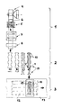
- the drawing shows, purely schematically, a system for carrying out the method, consisting of an input station 1, a subsequent molding station 2 and finally a transport path 3 with a welding device connected to it.
- the input station 1 comprises in particular a metal tape roll holder 4 (reel), a device 5 for straightening the metal tape 6, a cutting or punching device 7 for making possible cutouts in the tape, a cutting device 8 for cutting the tape to length and optionally a feed device for the tape.
- the cut-to-length pieces of tape (each intended to form a single lamella) are transported from the input station 1 to the forming station 2 and (in the form of a press) are brought into the definitive form there (see steps ad), in step d also welding bosses 10 in the lamella feet 9.9 'are impressed.
- the finished fins 11 are generally pushed one after the other onto the heating wall 12 lying upside down, aligned and individually welded (the flat tubes of the heating wall are already assembled to form an assembly).
- the convection fins 11 welded on one after the other (or possibly in groups) additionally stiffen the heating wall. If necessary, the end faces of the slats can be further stiffened by welding a connecting band (not shown).
- the heating wall 12 is moved forward on the table 13 (transport path) step by step, so that each lamella 11 can be placed in the correct place.
Landscapes
- Engineering & Computer Science (AREA)
- Physics & Mathematics (AREA)
- Mechanical Engineering (AREA)
- Thermal Sciences (AREA)
- General Engineering & Computer Science (AREA)
- Geometry (AREA)
- Bending Of Plates, Rods, And Pipes (AREA)
- Heat-Exchange Devices With Radiators And Conduit Assemblies (AREA)
- Shaping Metal By Deep-Drawing, Or The Like (AREA)
Abstract
Description
- Die vorliegende Erfindung betrifft ein Verfahren zur Bestückung von Heizwänden mit Konvektionslamellen, bei welchem die Lamellen auf die Heizwandrückseite aufgeschweisst werden und eine Anlage zur Durchführung des Verfahrens sowie nach dem Verfahren mit Konvektionslamellen bestückte Heizwände.
- Die heute stark verbreiteten Heizwände, bestehend aus parallel zueinander in einer Ebene angeordneten Flachrohren und diese untereinander verbindenden Sammelrohren für die Zu- und Abfuhr von Warmwasser, werden auf ihrer Rückseite in der Regel mit sog. Konvektionslamellen versehen.
- Ueblicherweise wird zur Bildung der Lamellen ein Blech gemäss vorgegebenen Dimensionen in einer Presse verformt und das Blech, einen zusammenhängenden Lamellenstrang bildend, auf Vorratsrollen gespeichert, um dann je nach Bedarf abgelängt und als zusammenhängendes Lamellenblech auf die Heizwandrückseite aufgeschweisst zu werden.
- Selbstverständlich sind zu diesem Zweck Lamellenbleche verschiedener Breiten für verschiedene Lamellenlängen zu verwenden.
- Diese Methode mag sich für grosse Serienfabrikationen eignen (wenn für eine grössere Serie immer dieselben Lamellenbleche gebraucht werden), ist jedoch aufwendig bei sogenannter auftragsbezogener Fertigung, d.h. einer Fertigung von Heizkörpern verschiedener Grösse, aber in beschränkter Stückzahl für einen bestimmten Besteller.
- Der erforderliche Lagerplatz, aufwendige Zwischentransporte, umständliches "Handling" und Anfall von Schnittabfall ist dabei besonders nachteilig. Falls die Lamellenbleche ab der Blechrolle (coil ) gefertigt und direkt der Weiterbearbeitung und dem Aufschweissen auf die Heizwand zugeführt werden, bedingt dies zudem eine hohe Umrüstzeit der Pressen (bei auftragsbezogener Fertigung).
- Aufgabe der vorliegenden Erfindung war es, diese bekannten Methoden an die Bedürfnisse der auftragsbezogenen Fertigung anzupassen oder eine für diese Fertigungsart optimalere Lösung zu finden.
- Diese Aufgabe wurde nun erfindungsgemäss dadurch gelöst, dass in einer Formstation ein Metallband ab einem Metallbandspeicher abgezogen und aus dem Band die Lamellen mit vorbestimmten Abmessungen bezüglich Teilung und Höhe geformt und gemäss einem Bestückungsplan auf Länge geschnitten werden und dass die so gefertigten Einzellamellen gemäss dem Bestückungsplan der Schweissstation zugeführt, auf der Heizwandrückseite ausgerichtet und auf diese aufgeschweisst werden.
- Die Grundidee besteht somit darin, die Bestükkung der Heizwände mit Konvektionslamellen mittels Einzellamellen durchzuführen.
- Diese scheinbar rückschrittige Lösung bringt für die auftragsbezogene Fertigung enorme Vorteile:
- - für eine bestimmte Lamellenform (d.h. bestimmte Teilung und Höhe der Lamellen) wird lediglich ein Band bestimmter Breite benötigt (einfache Rohmateriallagerhaltung);
- - einfaches Handling;
- - kein überflüssiger Materialverbrauch (d.h. Materialeinsparung, da keine nicht mehr verwendbaren Teile der Lamellen wegzutrennen sind, um vorspringenden Teilen der Heizwand, wie z.B. Aufhängebügeln, Platz zu machen);
- - einfache Lagerhaltung (Zwischenlager entfallen);
- - es wird nur ein Pressenwerkzeug für eine bestimmte Lamellenform benötigt (wesentliche Einsparung von Werkzeugkosten);
- - das Anbringen von Aussparungen ist vereinfacht und verursacht nur geringen Abfall;
- - eine (voll-) automatische Fertigung wird auch für kleine Stückzahlen möglich.
- Vorzugsweise wird das Band schon vor der eigentlichen Formgebung auf Länge geschnitten.
- Die verschiedenen Aussparungen können vor der Formgebung ausgeschnitten bzw. ausgestanzt werden.
- Vorzugsweise werden die geformten und abgelängten Lamellen nacheinander einzeln der Schweissstation zugeführt, in der vorgegebenen Stellung auf der Heizwandrückseite ausgerichtet und festgeschweisst.
- Eine zur Durchführung des Verfahrens geeignete Anlage zeichnet sich aus durch eine Eingangsstation mit einem Metallbandrollenhalter, Werkzeugen zum Ausschneiden bzw. Ausstanzen von Bandausnehmungen sowie einer Trennvorrichtung zum Ablängen von Bandabschnitten zur Bildung einzelner Lamellen, einer anschliessenden Formstation zur Formung der fertigen Lamelle und einer neben dieser angeordneten Transportbahn für mit Lamellen zu bestückenden Heizwände, mit zugehörigen Ausricht-, Schweiss- und Vorschubeinrichtungen.
- Die Erfindung wird nachstehend anhand der Zeichnung noch etwas näher erläutert. Es zeigt
- die einzige Figur rein schematisch eine Anlage zur Bestückung von Heizwänden mit Konvektionslamellen.
- Wie bereits erwähnt, liegt der Kern der Erfindung darin, dass die Bestückung der Heizwandrückseiten mit Konvektionslamellen mittels Einzellamellen erfolgt. Es versteht sich von selbst, dass jede Heizwand nur Lamellen eines Typs (Teilung, Höhe) enthält, welche jedoch gegebenenfalls an bestimmten Stellen verschiedene Länge aufweisen können, um Teile der Heizwand freizulassen. Dies wird dank des vorliegenden Verfahrens problemlos möglich, indem der Bestückungsplan entsprechende Lamellen verschiedener Länge vorsieht, und diese lediglich gemäss Plan in der passenden Reihenfolge aufzuschweissen sind.
- Der grundlegende Vorteil des erfindungsgemässen Verfahrens liegt jedoch darin, dass mit nur einem Presswerkzeug Heizwände verschiedener Höhe bzw. Breite ausgerüstet werden können, vorausgesetzt selbstredend, dass der gleiche Lamellentyp zu verwenden ist. Das Verfahren eignet sich somit besonders für die auftragsbezogene Fertigung.
- Die Lamellen sind lediglich auf die vorgegebene Länge zu fertigen und können dann nacheinander plaziert und aufgeschweisst werden (je nach Schweisseinrichtung gegebenenfalls auch in Gruppen, aber getrennt voneinander).
- Die Zeichnung zeigt rein schematisch eine Anlage zur Durchführung des Verfahrens, bestehend aus einer Eingangsstation 1, einer anschliessenden Formstation 2 und schliesslich einer an diese anschliessende Transportbahn 3 mit Schweisseinrichtung.
- Die Eingangsstation 1 umfasst insbesondere eine Metallbandrollen-Halterung 4 (Haspel), eine Einrichtung 5 zum Richten des Metallbandes 6, eine Schneid- oder Stanzeinrichtung 7 zum mustergemässen Anbringen von eventuellen Aussparungen in das Band, eine Schneidvorrichtung 8 zum Ablängen des Bandes und gegebenenfalls eine Vorschubeinrichtung für das Band.
- Die abgelängten Bandstücke (jeweils zur Bildung einer Einzellamelle vorgesehen) werden aus der Eingangsstation 1 in die Formstation 2 weitertransportiert und in dieser (als Presse ausgebildet) in die definitive Form gebracht (s. z.B. Schritte a-d), wobei im Schritt d noch Schweissbuckel 10 in die Lamellenfüsse 9,9' eingeprägt werden.
- Aus der Formstation 2 werden die fertigen Lamellen 11 in der Regel nacheinander auf die mit der Rückseite nach oben liegende Heizwand 12 geschoben, ausgerichtet und individuell festgeschweisst (die Flachrohre der Heizwand sind schon zu einer Baugruppe zusammengefügt). Die so nacheinander (oder gegebenenfalls gruppenweise) aufgeschweissten Konvektionslamellen 11 versteifen dabei die Heizwand zusätzlich. Bei Bedarf können die Stirnflächen der Lamellen noch durch Aufschweissen eines Verbindungsbandes (nicht dargestellt) weiter versteift werden. Die Heizwand 12 wird auf dem Tisch 13 (Transportbahn) schrittweise vorwärtsbewegt, so dass jede Lamelle 11 am richtigen Ort aufgesetzt werden kann.
Claims (10)
Applications Claiming Priority (2)
| Application Number | Priority Date | Filing Date | Title |
|---|---|---|---|
| CH346092A CH687911A5 (de) | 1992-11-09 | 1992-11-09 | Verfahren zur Bestueckung von Heizwaenden mit Konvektionslamellen und Anlage zur Durchfuehrung des Verfahrens. |
| CH3460/92 | 1992-11-09 |
Publications (2)
| Publication Number | Publication Date |
|---|---|
| EP0597256A1 true EP0597256A1 (de) | 1994-05-18 |
| EP0597256B1 EP0597256B1 (de) | 1997-01-22 |
Family
ID=4256425
Family Applications (1)
| Application Number | Title | Priority Date | Filing Date |
|---|---|---|---|
| EP19930116300 Expired - Lifetime EP0597256B1 (de) | 1992-11-09 | 1993-10-08 | Verfahren zur Bestückung von Heizwänden mit Konvektionslamellen und Anlage zur Durchführung des Verfahrens |
Country Status (3)
| Country | Link |
|---|---|
| EP (1) | EP0597256B1 (de) |
| CH (1) | CH687911A5 (de) |
| DE (1) | DE59305239D1 (de) |
Citations (4)
| Publication number | Priority date | Publication date | Assignee | Title |
|---|---|---|---|---|
| GB805521A (en) * | 1954-03-29 | 1958-12-10 | Egon Runte | Improvements in or relating to apparatus for heating or cooling buildings |
| CH391629A (fr) * | 1962-02-05 | 1965-05-15 | Runtal Holding Co Sa | Procédé et installation pour assembler les pièces d'un élément de radiateur par soudage |
| DE1652647A1 (de) * | 1968-01-19 | 1971-06-24 | Zentralinstitut Fuer Fertigung | Verfahren und eine Vorrichtung zum kontinuierlichen Fertigen von Wirbelblechen,die aus einem mehrzeilig aneinandergereihten,innerhalb jeweils einer Zeile versetzt angeordneten Hutprofil aufgebaut sind,vorzugsweise vom Coil |
| US3650233A (en) * | 1969-05-12 | 1972-03-21 | Young Radiator Co | Apparatus for forming sheet-metal fin-strips for heat-exchangers |
-
1992
- 1992-11-09 CH CH346092A patent/CH687911A5/de not_active IP Right Cessation
-
1993
- 1993-10-08 DE DE59305239T patent/DE59305239D1/de not_active Expired - Fee Related
- 1993-10-08 EP EP19930116300 patent/EP0597256B1/de not_active Expired - Lifetime
Patent Citations (4)
| Publication number | Priority date | Publication date | Assignee | Title |
|---|---|---|---|---|
| GB805521A (en) * | 1954-03-29 | 1958-12-10 | Egon Runte | Improvements in or relating to apparatus for heating or cooling buildings |
| CH391629A (fr) * | 1962-02-05 | 1965-05-15 | Runtal Holding Co Sa | Procédé et installation pour assembler les pièces d'un élément de radiateur par soudage |
| DE1652647A1 (de) * | 1968-01-19 | 1971-06-24 | Zentralinstitut Fuer Fertigung | Verfahren und eine Vorrichtung zum kontinuierlichen Fertigen von Wirbelblechen,die aus einem mehrzeilig aneinandergereihten,innerhalb jeweils einer Zeile versetzt angeordneten Hutprofil aufgebaut sind,vorzugsweise vom Coil |
| US3650233A (en) * | 1969-05-12 | 1972-03-21 | Young Radiator Co | Apparatus for forming sheet-metal fin-strips for heat-exchangers |
Non-Patent Citations (1)
| Title |
|---|
| "making radiators for large transformers", AUTOMATION, vol. 9, no. 6, June 1962 (1962-06-01), CLEVELAND US, pages 56 - 61 * |
Also Published As
| Publication number | Publication date |
|---|---|
| CH687911A5 (de) | 1997-03-27 |
| DE59305239D1 (de) | 1997-03-06 |
| EP0597256B1 (de) | 1997-01-22 |
Similar Documents
| Publication | Publication Date | Title |
|---|---|---|
| DE69201967T2 (de) | Verfahren und Vorrichtung zum Herstellen von dosenförmigen Kanalelementen aus Blech. | |
| EP0371956B1 (de) | Verfahren und Anlage zum Zuführen von Längselementen zu einer Schweissmaschine für Gitter oder Gitterroste | |
| DE2739962B2 (de) | Verfahren und Vorrichtung zur Herstellung eines Metallrohres | |
| DE3529160C2 (de) | ||
| DE2954233C2 (de) | ||
| DE3131736A1 (de) | Verfahren zur herstellung von waermetauschern mit rundgebogenen teilen, sowie gemaess dem verfahren hergestellter waermetauscher | |
| DE2423279A1 (de) | Aus plattenmaterial durch praegen geformte gegenstaende | |
| DE2940473A1 (de) | Verfahren und vorrichtung zur herstellung von metallprofilen | |
| DE69118667T2 (de) | Verfahren und Vorrichtung zum Anbringen von Verbindungsstellen-Anzeigelöchern in Fotopapier | |
| EP0597256B1 (de) | Verfahren zur Bestückung von Heizwänden mit Konvektionslamellen und Anlage zur Durchführung des Verfahrens | |
| DE3247824A1 (de) | Verfahren zur herstellung eines mit einer oeffnung versehenen teils | |
| DE2551453A1 (de) | Verfahren zum herstellen eines gliederfoerderbandes | |
| DE2163731C3 (de) | ||
| DE3439770C1 (de) | Verfahren zum Steuern von einer Profiliermaschine zugeordneten Arbeitsstationen und Profilieranlage | |
| DE4326142C2 (de) | Verfahren und Vorrichtung zur vollautomatischen Herstellung von Metallstäben für Stabgeflechtsgurte | |
| DE1961442B2 (de) | Vorrichtung zum Herstellen von Abstandhalter-Körben für den Stahlbetonbau | |
| EP0044880B1 (de) | Torblatt für ein Deckenglieder- oder Rolltor; Vorrichtung und Verfahren zur Herstellung eines Torblattes | |
| DE2711117A1 (de) | Verfahren und vorrichtung zur herstellung von dosendeckeln | |
| DE4312002C2 (de) | Verfahren zur Herstellung eines Torblattes | |
| DE3442466C2 (de) | ||
| DE60308423T2 (de) | Verfahren und vorrichtung zur herstellung von isolierplatten in form von dachziegeln | |
| DE19829451C2 (de) | Herstellungsverfahren von Konvektoren für Heizkörper | |
| DE102018102929B3 (de) | Vorrichtung und Arbeitsverfahren zur Herstellung eines Metallhaltebügels | |
| EP0042450A1 (de) | Verfahren zur Herstellung von Mänteln für Auspufftöpfe mit einer gefalzten Längsnaht und Vorrichtung zur Durchführung dieses Verfahrens | |
| EP0565129A1 (de) | Herstellung eines Torblattes |
Legal Events
| Date | Code | Title | Description |
|---|---|---|---|
| PUAI | Public reference made under article 153(3) epc to a published international application that has entered the european phase |
Free format text: ORIGINAL CODE: 0009012 |
|
| AK | Designated contracting states |
Kind code of ref document: A1 Designated state(s): BE DE FR IE IT |
|
| 17P | Request for examination filed |
Effective date: 19941111 |
|
| 17Q | First examination report despatched |
Effective date: 19950804 |
|
| GRAG | Despatch of communication of intention to grant |
Free format text: ORIGINAL CODE: EPIDOS AGRA |
|
| GRAH | Despatch of communication of intention to grant a patent |
Free format text: ORIGINAL CODE: EPIDOS IGRA |
|
| GRAH | Despatch of communication of intention to grant a patent |
Free format text: ORIGINAL CODE: EPIDOS IGRA |
|
| GRAA | (expected) grant |
Free format text: ORIGINAL CODE: 0009210 |
|
| AK | Designated contracting states |
Kind code of ref document: B1 Designated state(s): BE DE FR IE IT |
|
| ITF | It: translation for a ep patent filed | ||
| REF | Corresponds to: |
Ref document number: 59305239 Country of ref document: DE Date of ref document: 19970306 |
|
| REG | Reference to a national code |
Ref country code: IE Ref legal event code: FG4D Free format text: 71722 |
|
| ET | Fr: translation filed | ||
| PLBE | No opposition filed within time limit |
Free format text: ORIGINAL CODE: 0009261 |
|
| STAA | Information on the status of an ep patent application or granted ep patent |
Free format text: STATUS: NO OPPOSITION FILED WITHIN TIME LIMIT |
|
| 26N | No opposition filed | ||
| PGFP | Annual fee paid to national office [announced via postgrant information from national office to epo] |
Ref country code: IE Payment date: 20081015 Year of fee payment: 16 Ref country code: DE Payment date: 20081014 Year of fee payment: 16 |
|
| PGFP | Annual fee paid to national office [announced via postgrant information from national office to epo] |
Ref country code: BE Payment date: 20081009 Year of fee payment: 16 Ref country code: IT Payment date: 20081028 Year of fee payment: 16 |
|
| PGFP | Annual fee paid to national office [announced via postgrant information from national office to epo] |
Ref country code: FR Payment date: 20081014 Year of fee payment: 16 |
|
| BERE | Be: lapsed |
Owner name: S.A. *RUNTAL HOLDING CY Effective date: 20091031 |
|
| REG | Reference to a national code |
Ref country code: IE Ref legal event code: MM4A |
|
| REG | Reference to a national code |
Ref country code: FR Ref legal event code: ST Effective date: 20100630 |
|
| PG25 | Lapsed in a contracting state [announced via postgrant information from national office to epo] |
Ref country code: FR Free format text: LAPSE BECAUSE OF NON-PAYMENT OF DUE FEES Effective date: 20091102 Ref country code: DE Free format text: LAPSE BECAUSE OF NON-PAYMENT OF DUE FEES Effective date: 20100501 |
|
| PG25 | Lapsed in a contracting state [announced via postgrant information from national office to epo] |
Ref country code: IE Free format text: LAPSE BECAUSE OF NON-PAYMENT OF DUE FEES Effective date: 20091008 Ref country code: BE Free format text: LAPSE BECAUSE OF NON-PAYMENT OF DUE FEES Effective date: 20091031 |
|
| PG25 | Lapsed in a contracting state [announced via postgrant information from national office to epo] |
Ref country code: IT Free format text: LAPSE BECAUSE OF NON-PAYMENT OF DUE FEES Effective date: 20091008 |