EP0597384A1 - Elargissement d'échafaudage au moyen d'un console - Google Patents
Elargissement d'échafaudage au moyen d'un console Download PDFInfo
- Publication number
- EP0597384A1 EP0597384A1 EP93117860A EP93117860A EP0597384A1 EP 0597384 A1 EP0597384 A1 EP 0597384A1 EP 93117860 A EP93117860 A EP 93117860A EP 93117860 A EP93117860 A EP 93117860A EP 0597384 A1 EP0597384 A1 EP 0597384A1
- Authority
- EP
- European Patent Office
- Prior art keywords
- scaffolding
- widening
- scaffold
- console
- horizontal support
- Prior art date
- Legal status (The legal status is an assumption and is not a legal conclusion. Google has not performed a legal analysis and makes no representation as to the accuracy of the status listed.)
- Withdrawn
Links
- 239000000725 suspension Substances 0.000 claims description 4
- 238000009434 installation Methods 0.000 abstract 1
- 238000004519 manufacturing process Methods 0.000 description 3
- 229910000831 Steel Inorganic materials 0.000 description 1
- XAGFODPZIPBFFR-UHFFFAOYSA-N aluminium Chemical compound [Al] XAGFODPZIPBFFR-UHFFFAOYSA-N 0.000 description 1
- 229910052782 aluminium Inorganic materials 0.000 description 1
- 238000011161 development Methods 0.000 description 1
- 230000018109 developmental process Effects 0.000 description 1
- 238000006073 displacement reaction Methods 0.000 description 1
- 230000002349 favourable effect Effects 0.000 description 1
- 239000007787 solid Substances 0.000 description 1
- 239000010959 steel Substances 0.000 description 1
- 239000002023 wood Substances 0.000 description 1
Images
Classifications
-
- E—FIXED CONSTRUCTIONS
- E04—BUILDING
- E04G—SCAFFOLDING; FORMS; SHUTTERING; BUILDING IMPLEMENTS OR AIDS, OR THEIR USE; HANDLING BUILDING MATERIALS ON THE SITE; REPAIRING, BREAKING-UP OR OTHER WORK ON EXISTING BUILDINGS
- E04G1/00—Scaffolds primarily resting on the ground
- E04G1/15—Scaffolds primarily resting on the ground essentially comprising special means for supporting or forming platforms; Platforms
- E04G1/152—Platforms made of metal or with metal-supporting frame
-
- E—FIXED CONSTRUCTIONS
- E04—BUILDING
- E04G—SCAFFOLDING; FORMS; SHUTTERING; BUILDING IMPLEMENTS OR AIDS, OR THEIR USE; HANDLING BUILDING MATERIALS ON THE SITE; REPAIRING, BREAKING-UP OR OTHER WORK ON EXISTING BUILDINGS
- E04G1/00—Scaffolds primarily resting on the ground
- E04G1/15—Scaffolds primarily resting on the ground essentially comprising special means for supporting or forming platforms; Platforms
- E04G1/154—Non-detachably fixed and secured connections between platform and scaffold
-
- E—FIXED CONSTRUCTIONS
- E04—BUILDING
- E04G—SCAFFOLDING; FORMS; SHUTTERING; BUILDING IMPLEMENTS OR AIDS, OR THEIR USE; HANDLING BUILDING MATERIALS ON THE SITE; REPAIRING, BREAKING-UP OR OTHER WORK ON EXISTING BUILDINGS
- E04G5/00—Component parts or accessories for scaffolds
- E04G5/06—Consoles; Brackets
-
- E—FIXED CONSTRUCTIONS
- E04—BUILDING
- E04G—SCAFFOLDING; FORMS; SHUTTERING; BUILDING IMPLEMENTS OR AIDS, OR THEIR USE; HANDLING BUILDING MATERIALS ON THE SITE; REPAIRING, BREAKING-UP OR OTHER WORK ON EXISTING BUILDINGS
- E04G5/00—Component parts or accessories for scaffolds
- E04G5/06—Consoles; Brackets
- E04G5/061—Consoles; Brackets specially adapted for attachment to scaffolds
Definitions
- scaffold brackets are already widely used in scaffolding.
- scaffolding that is built along house walls is often widened above the eaves in both directions in order to obtain a larger working platform at this height.
- scaffold brackets are attached on both sides by so-called vertical frames, in the upper cross member of which additional scaffold floors can be inserted.
- the width of the cross member is matched to the center distance of the two vertical struts of the vertical frame, so that previously the same scaffold floors could be inserted both in the upper cross strut of a vertical frame and in the cross members of such scaffold consoles.
- This standard floor is dimensioned such that diagonal struts can be hung on the outside of the scaffold over several floors in the vertical frame without these diagonal struts protruding from the vertical struts of the vertical frame.
- a gap resulted between the shelves of the scaffold and the scaffold console, which had a width of approximately 120 mm with conventional standard scaffolds. This gap was usually covered with a cover for occupational safety.
- the object of the invention is therefore to propose a widening of the scaffolding which meets the requirements in accordance with the regulations, withstands the rough conditions of use on site and can be produced with as little effort as possible.
- the horizontal support of the scaffold console has a projection which, in the installed state, engages in a recess in a widened scaffold floor or its support or suspension elements.
- the above-mentioned gap between two shelves is naturally reduced in order to meet the above-mentioned regulations.
- the protrusion on the horizontal support of the scaffold console also prevents a standard scaffold floor of the main scaffold from being hung or placed on the horizontal support of the scaffold console. This reliably ensures that in the scaffold bracket used for the scaffolding extension only the specially provided floors with the enlargement are used and not negligently the usual narrow standard floors.
- the horizontal support of the scaffold console In order to be able to continue to manufacture the scaffold console from standard parts, it is advisable to design the horizontal support of the scaffold console as a U-profile part. Such a configuration of the horizontal beam corresponds to the cross beam of a commonly used vertical frame.
- the bolt can be attached inside the profile. This leaves the outer shape of the cross member unchanged, which can be particularly advantageous when loading. This also avoids an additional abutting edge, as it would represent a bolt protruding from the horizontal beam, which in turn benefits occupational safety.
- the scaffold floor that can be inserted into such a cross member advantageously has hook-in tabs for suspending the bottom in the U-profile of the horizontal beam, at least one of the hook-in tabs being provided with a recess for the bolt within the U-profile.
- Such an anti-tilt device is advantageously designed as an angle on the top of the horizontal support, under which the floor can be inserted during assembly with at least one hanging tab. This provides a solid anti-tipping device that does not require any additional effort during assembly. Of course, such a tilt protection could also be attached to the cross member of a conventional vertical frame in order to secure the usual standard floors against tipping.
- the side broadening of the shelves is preferably increased somewhat in height compared to the floor level of the standard shelves used in the main scaffold. This makes it possible to use such a shelf in the case of various shelves in the main frame which have been customary to date.
- Such standard floors have a slightly larger height in an aluminum version than in a steel or wood version.
- a widespread shelf according to the invention with a slightly increased widening can be used with all these standard shelves.
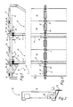
- FIGs 1 and 2 the upper end of a widened frame 1 is shown.
- two longitudinal struts 2, 3 of a vertical frame 4 (not shown completely) lead upward to a cross strut 5, with struts 6, 7 stiffening the vertical frame 4.
- a large 8 and a small console 9 are attached to each side of the vertical frame 4.
- the two brackets 8, 9 are fastened to the vertical frame 4 by screw connections 10, 11.
- the two horizontal beams 12, 13 extend the cross strut 5 on both sides.
- two standard bases 14 with hook-in tabs 15 are suspended in the open U-profile of the cross strut 5.
- a gap 16 results between the standard bases 14 of the cross member 5 and the two shelves 17, 18 of the horizontal support 12.
- One 17 of the bases 17, 18 inserted into the horizontal support 12 of the large bracket 8 is also a standard base.
- the widening floor 18 pointing towards the main scaffold, however, has a widening 19 as well as the widening floor 20 inserted into the horizontal support 13 of the small console 9 has an enlargement 21.
- the U-shaped horizontal supports 12, 13 are penetrated by bolts 22, 23.
- Two brackets 30, 31 overlap two suspension brackets 32, 33 to prevent tipping.
- the angles 30, 31 are firmly attached to the horizontal beams 12, 13.
- FIG. 10 An extension base 34 according to the invention, which can be used both in the small console 9 and in the large console 8 as an extension base 18 or 20, is shown in FIG. In this illustration, the recess 35 is made particularly clear. The height h of the floor level 36 with respect to the widening 37 also emerges well in this illustration.
- the brackets 8, 9 are first screwed to the vertical frame 4. Subsequently, the floors 17, 18, 20 are inserted into the horizontal beams 12, 13 of the two brackets 8, 9.
- the two widening bases 18, 20 are inserted in such a way that the suspension lugs 32, 33 are first pushed without a recess 26, 27 at angles 30, 31 when the widening base is raised obliquely.
- the fitter can stand on the standard floors 14 of the main scaffold. Then he lowers the bottoms 18, 20 so that the hook-in tabs 28, 29 with their recesses 26, 27 engage the bolts 22, 23 on their parts 24, 25 protruding inside the U-shaped horizontal beams 12, 13.
- the widening bases 18, 20 are thus secured both against lateral displacement and against tipping.
Landscapes
- Engineering & Computer Science (AREA)
- Architecture (AREA)
- Mechanical Engineering (AREA)
- Civil Engineering (AREA)
- Structural Engineering (AREA)
- Furniture Connections (AREA)
- Movable Scaffolding (AREA)
Applications Claiming Priority (2)
| Application Number | Priority Date | Filing Date | Title |
|---|---|---|---|
| DE4238241 | 1992-11-12 | ||
| DE4238241A DE4238241A1 (de) | 1992-11-12 | 1992-11-12 | Gerüstverbreiterung mit einer Gerüstkonsole |
Publications (1)
| Publication Number | Publication Date |
|---|---|
| EP0597384A1 true EP0597384A1 (fr) | 1994-05-18 |
Family
ID=6472746
Family Applications (1)
| Application Number | Title | Priority Date | Filing Date |
|---|---|---|---|
| EP93117860A Withdrawn EP0597384A1 (fr) | 1992-11-12 | 1993-11-04 | Elargissement d'échafaudage au moyen d'un console |
Country Status (2)
| Country | Link |
|---|---|
| EP (1) | EP0597384A1 (fr) |
| DE (1) | DE4238241A1 (fr) |
Cited By (2)
| Publication number | Priority date | Publication date | Assignee | Title |
|---|---|---|---|---|
| EP1070807A1 (fr) * | 1999-07-17 | 2001-01-24 | Wilhelm Layher Vermögensverwaltungs-GmbH | Console d'échafaudage |
| EP2949834A1 (fr) * | 2014-05-30 | 2015-12-02 | Tobler AG | Console de fixation pour plateaux d'échafaudage, plateau d'échafaudage, et échafaudage |
Families Citing this family (1)
| Publication number | Priority date | Publication date | Assignee | Title |
|---|---|---|---|---|
| DE9316507U1 (de) * | 1993-10-28 | 1994-11-03 | Fakler, Eugen, 88471 Laupheim | Hubarbeitsbühne mit Hilfsplattform |
Citations (4)
| Publication number | Priority date | Publication date | Assignee | Title |
|---|---|---|---|---|
| US4340130A (en) * | 1980-07-24 | 1982-07-20 | Kwikform America, Inc. | Scaffold frame header |
| US4583618A (en) * | 1984-11-15 | 1986-04-22 | Zimmerman Rudi M | Coordinated stage system with articulate means |
| GB2201715A (en) * | 1987-03-03 | 1988-09-07 | Kwikform Ltd Gkn | Folding staging support assembly |
| DE3832066A1 (de) * | 1987-09-23 | 1989-04-06 | Geb Layher Langer | Geruestbodenteil |
Family Cites Families (2)
| Publication number | Priority date | Publication date | Assignee | Title |
|---|---|---|---|---|
| DE6750561U (de) * | 1968-09-26 | 1969-01-09 | Huennebeck Ag | Zerlegbares geruest |
| DE9112488U1 (de) * | 1991-10-08 | 1992-07-16 | Günter Rux GmbH, 5800 Hagen | Metallstandgerüst |
-
1992
- 1992-11-12 DE DE4238241A patent/DE4238241A1/de not_active Withdrawn
-
1993
- 1993-11-04 EP EP93117860A patent/EP0597384A1/fr not_active Withdrawn
Patent Citations (4)
| Publication number | Priority date | Publication date | Assignee | Title |
|---|---|---|---|---|
| US4340130A (en) * | 1980-07-24 | 1982-07-20 | Kwikform America, Inc. | Scaffold frame header |
| US4583618A (en) * | 1984-11-15 | 1986-04-22 | Zimmerman Rudi M | Coordinated stage system with articulate means |
| GB2201715A (en) * | 1987-03-03 | 1988-09-07 | Kwikform Ltd Gkn | Folding staging support assembly |
| DE3832066A1 (de) * | 1987-09-23 | 1989-04-06 | Geb Layher Langer | Geruestbodenteil |
Cited By (2)
| Publication number | Priority date | Publication date | Assignee | Title |
|---|---|---|---|---|
| EP1070807A1 (fr) * | 1999-07-17 | 2001-01-24 | Wilhelm Layher Vermögensverwaltungs-GmbH | Console d'échafaudage |
| EP2949834A1 (fr) * | 2014-05-30 | 2015-12-02 | Tobler AG | Console de fixation pour plateaux d'échafaudage, plateau d'échafaudage, et échafaudage |
Also Published As
| Publication number | Publication date |
|---|---|
| DE4238241A1 (de) | 1994-05-19 |
Similar Documents
| Publication | Publication Date | Title |
|---|---|---|
| EP0918912B2 (fr) | Echafaudage de facade demontable | |
| EP1395723A2 (fr) | Echafaudage demontable | |
| DE3832066A1 (de) | Geruestbodenteil | |
| EP3931411A1 (fr) | Cadre de coffrage, élément de coffrage, coffrage de plafond et procédé | |
| DE7617464U1 (de) | Stuetzvorrichtung, insbesondere fuer traeger von schaleinrichtungen im betonbau | |
| EP0308882A2 (fr) | Plate-forme pour échafaudages | |
| AT390108B (de) | Schutzvorrichtung fuer metallgerueste | |
| EP1070807A1 (fr) | Console d'échafaudage | |
| DE202022104065U1 (de) | Treppenwange | |
| DE3122593C2 (fr) | ||
| EP3947852B1 (fr) | Dispositif de garde-corps, à savoir garde-corps pour un échafaudage et procédé de montage d'un dispositif de garde-corps | |
| EP0597384A1 (fr) | Elargissement d'échafaudage au moyen d'un console | |
| DE3824922A1 (de) | Holzleiterngeruest mit aufstiegseinrichtungen | |
| DE102022133321A1 (de) | Gerüst, insbesondere fahrgerüst | |
| DE3401906A1 (de) | Vorrichtung zur haengenden befestigung eines geruestelements | |
| EP1362149B1 (fr) | Structure de connexion pour un cadre d'echafaudage | |
| DE19500705A1 (de) | Leitergestützte Arbeitsplattform | |
| DE4114328C2 (de) | Vorrichtung zum hängenden Befestigen eines Konsolgerüstelements | |
| DE20004389U1 (de) | Bauelementensatz für ein Gerüst | |
| EP2275625A2 (fr) | Construction d'échafaudage pour un échafaudage principal et un second échafaudage, notamment un escalier d'échafaudage | |
| DE3040707C2 (fr) | ||
| WO2004054406A1 (fr) | Element de support a crochet en t | |
| DE10006094A1 (de) | Gerüsttreppensystem | |
| DE202022105807U1 (de) | Treppenwange | |
| DE1929732U (de) | Fassadenverkleidungssatz. |
Legal Events
| Date | Code | Title | Description |
|---|---|---|---|
| PUAI | Public reference made under article 153(3) epc to a published international application that has entered the european phase |
Free format text: ORIGINAL CODE: 0009012 |
|
| AK | Designated contracting states |
Kind code of ref document: A1 Designated state(s): AT BE CH DE FR GB IT LI NL |
|
| STAA | Information on the status of an ep patent application or granted ep patent |
Free format text: STATUS: THE APPLICATION IS DEEMED TO BE WITHDRAWN |
|
| 18D | Application deemed to be withdrawn |
Effective date: 19941119 |