EP0597413A1 - Tourelle porte-outil - Google Patents
Tourelle porte-outil Download PDFInfo
- Publication number
- EP0597413A1 EP0597413A1 EP93118042A EP93118042A EP0597413A1 EP 0597413 A1 EP0597413 A1 EP 0597413A1 EP 93118042 A EP93118042 A EP 93118042A EP 93118042 A EP93118042 A EP 93118042A EP 0597413 A1 EP0597413 A1 EP 0597413A1
- Authority
- EP
- European Patent Office
- Prior art keywords
- turret
- angular position
- teeth
- indexing
- asynchronous motor
- Prior art date
- Legal status (The legal status is an assumption and is not a legal conclusion. Google has not performed a legal analysis and makes no representation as to the accuracy of the status listed.)
- Granted
Links
- 238000000034 method Methods 0.000 claims description 16
- 238000004804 winding Methods 0.000 claims description 6
- 230000000977 initiatory effect Effects 0.000 claims 1
- 230000001360 synchronised effect Effects 0.000 claims 1
- 238000010586 diagram Methods 0.000 description 7
- 210000000078 claw Anatomy 0.000 description 5
- 238000006073 displacement reaction Methods 0.000 description 3
- 230000001133 acceleration Effects 0.000 description 2
- 244000145845 chattering Species 0.000 description 2
- 230000003111 delayed effect Effects 0.000 description 2
- 230000001934 delay Effects 0.000 description 1
- 238000003475 lamination Methods 0.000 description 1
- 230000004048 modification Effects 0.000 description 1
- 238000012986 modification Methods 0.000 description 1
- 230000000149 penetrating effect Effects 0.000 description 1
Images



Classifications
-
- B—PERFORMING OPERATIONS; TRANSPORTING
- B23—MACHINE TOOLS; METAL-WORKING NOT OTHERWISE PROVIDED FOR
- B23Q—DETAILS, COMPONENTS, OR ACCESSORIES FOR MACHINE TOOLS, e.g. ARRANGEMENTS FOR COPYING OR CONTROLLING; MACHINE TOOLS IN GENERAL CHARACTERISED BY THE CONSTRUCTION OF PARTICULAR DETAILS OR COMPONENTS; COMBINATIONS OR ASSOCIATIONS OF METAL-WORKING MACHINES, NOT DIRECTED TO A PARTICULAR RESULT
- B23Q16/00—Equipment for precise positioning of tool or work into particular locations not otherwise provided for
- B23Q16/02—Indexing equipment
- B23Q16/08—Indexing equipment having means for clamping the relatively movable parts together in the indexed position
- B23Q16/10—Rotary indexing
- B23Q16/102—Rotary indexing with a continuous drive
-
- H—ELECTRICITY
- H02—GENERATION; CONVERSION OR DISTRIBUTION OF ELECTRIC POWER
- H02P—CONTROL OR REGULATION OF ELECTRIC MOTORS, ELECTRIC GENERATORS OR DYNAMO-ELECTRIC CONVERTERS; CONTROLLING TRANSFORMERS, REACTORS OR CHOKE COILS
- H02P25/00—Arrangements or methods for the control of AC motors characterised by the kind of AC motor or by structural details
- H02P25/16—Arrangements or methods for the control of AC motors characterised by the kind of AC motor or by structural details characterised by the circuit arrangement or by the kind of wiring
- H02P25/18—Arrangements or methods for the control of AC motors characterised by the kind of AC motor or by structural details characterised by the circuit arrangement or by the kind of wiring with arrangements for switching the windings, e.g. with mechanical switches or relays
- H02P25/20—Arrangements or methods for the control of AC motors characterised by the kind of AC motor or by structural details characterised by the circuit arrangement or by the kind of wiring with arrangements for switching the windings, e.g. with mechanical switches or relays for pole-changing
-
- B—PERFORMING OPERATIONS; TRANSPORTING
- B23—MACHINE TOOLS; METAL-WORKING NOT OTHERWISE PROVIDED FOR
- B23Q—DETAILS, COMPONENTS, OR ACCESSORIES FOR MACHINE TOOLS, e.g. ARRANGEMENTS FOR COPYING OR CONTROLLING; MACHINE TOOLS IN GENERAL CHARACTERISED BY THE CONSTRUCTION OF PARTICULAR DETAILS OR COMPONENTS; COMBINATIONS OR ASSOCIATIONS OF METAL-WORKING MACHINES, NOT DIRECTED TO A PARTICULAR RESULT
- B23Q2220/00—Machine tool components
- B23Q2220/002—Tool turrets
-
- Y—GENERAL TAGGING OF NEW TECHNOLOGICAL DEVELOPMENTS; GENERAL TAGGING OF CROSS-SECTIONAL TECHNOLOGIES SPANNING OVER SEVERAL SECTIONS OF THE IPC; TECHNICAL SUBJECTS COVERED BY FORMER USPC CROSS-REFERENCE ART COLLECTIONS [XRACs] AND DIGESTS
- Y10—TECHNICAL SUBJECTS COVERED BY FORMER USPC
- Y10T—TECHNICAL SUBJECTS COVERED BY FORMER US CLASSIFICATION
- Y10T29/00—Metal working
- Y10T29/51—Plural diverse manufacturing apparatus including means for metal shaping or assembling
- Y10T29/5152—Plural diverse manufacturing apparatus including means for metal shaping or assembling with turret mechanism
- Y10T29/5165—Plural diverse manufacturing apparatus including means for metal shaping or assembling with turret mechanism including rotating and/or locking means
-
- Y—GENERAL TAGGING OF NEW TECHNOLOGICAL DEVELOPMENTS; GENERAL TAGGING OF CROSS-SECTIONAL TECHNOLOGIES SPANNING OVER SEVERAL SECTIONS OF THE IPC; TECHNICAL SUBJECTS COVERED BY FORMER USPC CROSS-REFERENCE ART COLLECTIONS [XRACs] AND DIGESTS
- Y10—TECHNICAL SUBJECTS COVERED BY FORMER USPC
- Y10T—TECHNICAL SUBJECTS COVERED BY FORMER US CLASSIFICATION
- Y10T29/00—Metal working
- Y10T29/51—Plural diverse manufacturing apparatus including means for metal shaping or assembling
- Y10T29/5152—Plural diverse manufacturing apparatus including means for metal shaping or assembling with turret mechanism
- Y10T29/5165—Plural diverse manufacturing apparatus including means for metal shaping or assembling with turret mechanism including rotating and/or locking means
- Y10T29/5167—Lock means for tool or work turrets
-
- Y—GENERAL TAGGING OF NEW TECHNOLOGICAL DEVELOPMENTS; GENERAL TAGGING OF CROSS-SECTIONAL TECHNOLOGIES SPANNING OVER SEVERAL SECTIONS OF THE IPC; TECHNICAL SUBJECTS COVERED BY FORMER USPC CROSS-REFERENCE ART COLLECTIONS [XRACs] AND DIGESTS
- Y10—TECHNICAL SUBJECTS COVERED BY FORMER USPC
- Y10T—TECHNICAL SUBJECTS COVERED BY FORMER US CLASSIFICATION
- Y10T74/00—Machine element or mechanism
- Y10T74/14—Rotary member or shaft indexing, e.g., tool or work turret
- Y10T74/1488—Control means
-
- Y—GENERAL TAGGING OF NEW TECHNOLOGICAL DEVELOPMENTS; GENERAL TAGGING OF CROSS-SECTIONAL TECHNOLOGIES SPANNING OVER SEVERAL SECTIONS OF THE IPC; TECHNICAL SUBJECTS COVERED BY FORMER USPC CROSS-REFERENCE ART COLLECTIONS [XRACs] AND DIGESTS
- Y10—TECHNICAL SUBJECTS COVERED BY FORMER USPC
- Y10T—TECHNICAL SUBJECTS COVERED BY FORMER US CLASSIFICATION
- Y10T74/00—Machine element or mechanism
- Y10T74/14—Rotary member or shaft indexing, e.g., tool or work turret
- Y10T74/1494—Locking means
Definitions
- the invention relates to a tool turret which has the features of the preamble of claim 1.
- the invention is therefore based on the object of creating a tool turret which allows such a reduction in the switching time to be achieved without, on the other hand, requiring a considerably higher outlay. This object is achieved by a tool turret with the features of claim 1.
- the switching time can be shortened considerably by first changing the angle of the turret to one Speed is accelerated, which is higher than the indexing speed, preferably twice as large as this.
- the motor In order for the indexing to take place at the indexing speed, the motor only has to be switched back to the number of pole pairs resulting from the indexing speed in good time before the new angular position is reached. He then brakes the turret to the indexing speed so that the turret can be stopped abruptly by means of the pre-indexing bolt.
- the turret of which is made by means of a locking member which can be displaced in the direction of the axis of rotation of the turret, which in the locking position engages in two toothed rings of the turret or the turret housing at the same time with a plane toothing, and the axial displacement of the locking member by rotation of one which can be driven by the drive motor Control member is controlled relative to the locking member, the inertia of the turret during the braking process due to the pole switching of the drive motor to a rotation of the control member relative to the locking member.
- the signal for the pole changeover and thus for the beginning of the braking process can be generated by the angular position transmitter of the tool turret, if the angular position transmitter makes this possible, at the desired time, which is preferably the latest possible time and corresponds, for example, to an angular position of 20 before the angular position, in which the locking takes place.
- the desired time which is preferably the latest possible time and corresponds, for example, to an angular position of 20 before the angular position, in which the locking takes place.
- the tool turret according to the invention is preferably designed according to claim 4.
- the signal delay element has an adjustable delay time in order to adapt the time delay to the conditions of the tool turret and, in particular, to be able to adjust the size of the angle between two successive angular positions.
- one tooth or one tooth gap for each selectable angular position, one can of course also provide groups of teeth and tooth spaces. It only has to be ensured that there is still space between these groups for the contact surfaces.
- a tool turret the turret 1 is adjustable in twelve different angular positions, so that a switching step, i.e. a rotation from one angular position to the next angular position, extends over a swivel angle of 30, differs from the known tool turrets of this type with a three-phase asynchronous motor 2 as Drive for the turret 1 by a modified control device 3 and a design of the stator winding of the three-phase asynchronous motor 2 such that it is suitable for a Dahlander circuit.
- the larger of the two selectable pole pair numbers of the three-phase asynchronous motor 2 is assigned to the indexing speed, that is to say the speed at which the turret head moves into the new angular position, so that when a pre-indexing pin 4 falls for the purpose of stopping the turret head 1 in the new angular position, the permissible mechanical load the components involved in this abrupt shutdown of the turret 1 are not exceeded.
- the second selectable number of pole pairs therefore results in a maximum speed of the turret 1, which is twice the indexing speed.
- the indexing speed is n i
- the second speed is 2n ; featured.
- the mode of operation of the control device 3 depends on whether or not the indexing speed n i can be significantly exceeded before the braking process begins. Is a significant overshoot possible, which is assumed in Fig. 1, then the angular position transmitter 7 of the tool turret, depending on whether it is able to emit signals only in a position allowing a locking or in other angular positions, at the beginning of the switching process or at a later point in time Embodiment in an angular position of 10 °, a signal to the control device 3.
- the brake signal is delayed by a delay element 9 until the latest possible start of braking, that is, the time at which a switch 5 switches the three-phase asynchronous motor 2 to the larger number of pole pairs must have brought about.
- no delay element is required because the angle of rotation at which the angular position transmitter 7 generates the signal is selected such that the braking process starts in good time, taking into account the circuit-related delays which, in the exemplary embodiment, lead to the speed still increasing first and thus the indexing speed n i is reached shortly before the new switching position of the turret 1, which is 30 ° in the exemplary embodiment.
- the turret 1 With the indexing speed n i , the turret 1 is then moved on until the pre-fixing bolt 4, which is designed and operates in the usual way, based on a signal generated by the angular position transmitter 7, into a bore in the turret 1 or, as in the exemplary embodiment, a flange-shaped component 8 firmly connected to it occurs, whereby the turret 1 is stopped suddenly in the new angular position. Then it is aligned with the help of a locking device to its exact angular position and locked in this.
- the switch-on signal generated by the control device 3 at the beginning of the turning process is via a direct connection is supplied to the switch 5, the three-phase asynchronous motor 2 is connected to the energy supply network 6 not with the smaller, but with the larger of the two pole pair numbers.
- the turret 1 is thereby accelerated to the indexing speed n i in a very short time. At this indexing speed, the turret 1 then moves on until it has reached the next angular position. In this new angular position, the indexing pin 4 engages.
- the control device 3 If, on the other hand, as shown in FIG. 2, the turret 1 is to be rotated further by two switching steps, that is to say 60 ° in the exemplary embodiment, the control device 3 generates a first signal which is fed to the switch 5 via a second direct connection. Based on this signal, the latter selects the smaller of the two pole pair numbers and connects the three-phase asynchronous motor 2 to the energy supply network 6. The turret head 1 is therefore accelerated to twice the indexing speed, that is to say the speed 2n i . At this speed, it moves through the next angular position.
- this brake signal occurs at an output of the control device 3, which is connected to the input of the signal delay element 9, the delay time of which can be adjustable.
- the delay time of the signal delay element 9 is selected so that the pole changeover of the three-phase asynchronous motor 2 to its higher number of pole pairs takes place at a time which corresponds to a pivoting angle of approximately 10 in the exemplary embodiment.
- no signal delay element is required because the control device receives the brake signal at the correct time and forwards it to the switch 5.
- the three-phase asynchronous motor 2 As a result of the three-phase asynchronous motor 2 running over-synchronously after the pole changeover, it brakes the turret head 1 down to the indexing speed n i , which is reached shortly before the turret head 1 reaches the new angular position at 60. It is therefore ensured that the turret 1 has the indexing speed n i when entering the new angular position. Therefore, based on a signal from the angular position sensor 7, the pre-indexing pin 4 can now come in and abruptly stop the turret 1. At the same time, the three-phase asynchronous motor 2 is disconnected from the energy supply network 6 on the basis of a signal transmitted directly from the control device 3 to the switch 5. The subsequent precise positioning of the turret 1 and its locking in the new position takes place in the manner described below.
- the turret 1 can be rotated into a new angular position not only in one direction of rotation, but also in the opposite direction of rotation.
- Fig. 3 shows this using the example of a rotation by three switching steps.
- the control device 3 After accelerating to the maximum speed of 2n ;
- the control device 3 When the vehicle passes through the penultimate angular position, the control device 3 generates the brake signal, which is initially rendered ineffective by the signal delay element 9. 3, is initiated at a point in time which ensures that the indexing speed n i is reached shortly before the new angular position.
- the switching times cannot be reduced by half in a single switching step and when twisted over more than one switching step.
- the switching times can be at least increased Reduce 80% - 70% of the switching time obtained with a swivel movement with the indexing speed n i .
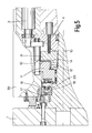
- the three-phase asynchronous motor 2 drives, via an intermediate gear, a control member 11 which is rotatably arranged on a drive shaft 10 and which has a cam track on its end face facing the turret 1.
- the control member 11 is supported by a spring assembly 12, which is supported on a shoulder of the drive shaft 10, which is screwed to the turret 1, and exerts a spring force on the control member 11 against the turret 1.
- the drive shaft 10 is driven from the control member 11 with the aid of claws 13 projecting in the axial direction, each of which engages in a groove 14 of the flange-shaped component 8 of the drive shaft 10.
- the width of the grooves 14 measured in the circumferential direction is substantially larger than the width of the claws 13 measured in this direction.
- a ring 17 which is arranged concentrically to the drive axis 10, is screwed to the turret housing 25 and has a face toothing on its end face facing the control member 11, which has a number of teeth 17 that is equal to the number of selectable angular positions 'and a corresponding number of tooth gaps 17 ".
- the teeth 17' and the tooth gaps 17" have a trapezoidal profile.
- a correspondingly designed toothed ring 18 is provided on a flange part of the drive shaft 10.
- a locking member 19 is arranged on the drive shaft 10 so as to be rotatable and displaceable in its longitudinal direction, which on its end face facing the ring 17 and the toothed ring 18 is one of the number of selectable angular positions has the corresponding number of teeth 19 'and tooth gaps 19 ".
- the teeth 19' and the tooth gaps 19" have the same profile as the teeth 17 'and the tooth gaps 17 ".
- the head ends of the teeth 19' also lie in a common radial plane .
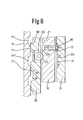
- Rollers 20 mounted rotatably in the locking member 19 run on the cam track of the control member 11, which forms a flat section 22 for each of the rollers 20 between two recesses 21. As shown in FIG. 6, when the locking member 19 is in its locking position, the roller 20 rests on the flat section 22. In this position, the bolt 16 is engaged in the central conical bore 23 in the base of the groove 14.
- the turret 1 is unlocked in that the three-phase asynchronous motor 2 initially only rotates the control member 11.
- the roller 20 moves into one or the other of the two depressions 21, as a result of which the locking member 19 moves into the unlocking position shown in FIG. 7, into which its teeth 19 'completely come out of the tooth gaps 17 "of the ring 17 and also from those of the toothed ring 18. Only when, as also shown in FIG. 7, the claws 13 come into contact with the lateral boundary surface of the grooves 14, the drive shaft 10 and together with it the turret head 1 rotate transferred.
- the pressure of the teeth 19 'on the top surfaces of the teeth 17' supports the braking of the locking member 19 and at the end of the braking process the alignment of the rollers 20 back to the deepest point of the recess 21.
- the locking member 19 can therefore be rotated by a Control member 11 are pushed in the opposite direction of rotation into the locking position in which the teeth 19 'are in play-free engagement with the tooth gaps 17' and the corresponding tooth gaps of the toothed ring 18.
- the claws 13 are again aligned with the center of the grooves 14, the bolts 16 falling into the central tapered bore.
Landscapes
- Engineering & Computer Science (AREA)
- Mechanical Engineering (AREA)
- Power Engineering (AREA)
- Machine Tool Positioning Apparatuses (AREA)
- Cutting Tools, Boring Holders, And Turrets (AREA)
- Machine Tool Units (AREA)
Applications Claiming Priority (2)
| Application Number | Priority Date | Filing Date | Title |
|---|---|---|---|
| DE4238281 | 1992-11-13 | ||
| DE4238281A DE4238281C2 (de) | 1992-11-13 | 1992-11-13 | Werkzeugrevolver |
Publications (2)
| Publication Number | Publication Date |
|---|---|
| EP0597413A1 true EP0597413A1 (fr) | 1994-05-18 |
| EP0597413B1 EP0597413B1 (fr) | 1996-09-18 |
Family
ID=6472767
Family Applications (1)
| Application Number | Title | Priority Date | Filing Date |
|---|---|---|---|
| EP93118042A Expired - Lifetime EP0597413B1 (fr) | 1992-11-13 | 1993-11-08 | Tourelle porte-outil |
Country Status (4)
| Country | Link |
|---|---|
| US (1) | US5339504A (fr) |
| EP (1) | EP0597413B1 (fr) |
| DE (2) | DE4238281C2 (fr) |
| ES (1) | ES2092205T3 (fr) |
Cited By (3)
| Publication number | Priority date | Publication date | Assignee | Title |
|---|---|---|---|---|
| WO2009012875A1 (fr) * | 2007-07-26 | 2009-01-29 | Sauter Feinmechanik Gmbh | Unité de tourelle porte-outils pour une machine-outil |
| EP3023195A1 (fr) * | 2014-11-19 | 2016-05-25 | Duplomatic Automation S.r.l. | Tourelle porte-outils |
| ITUB20153942A1 (it) * | 2015-09-28 | 2017-03-28 | Duplomatic Automation S R L | Torretta porta utensili con freno coassiale |
Families Citing this family (17)
| Publication number | Priority date | Publication date | Assignee | Title |
|---|---|---|---|---|
| US5682658A (en) * | 1996-03-04 | 1997-11-04 | Utica Enterprises, Inc. | Rotary index table assembly |
| US6244495B1 (en) | 1998-11-06 | 2001-06-12 | United Technologies Corporation | Gripper |
| US6354482B1 (en) | 1998-11-06 | 2002-03-12 | United Technologies Corporation | Friction welder |
| US6240807B1 (en) * | 1999-03-03 | 2001-06-05 | Chick Workholding Solutions, Inc. | Indexing apparatus |
| DE19919739C1 (de) * | 1999-04-30 | 2000-10-12 | Sauter Kg Feinmechanik | Werkzeugrevolver |
| JP3995558B2 (ja) * | 2002-08-20 | 2007-10-24 | シチズンホールディングス株式会社 | タレット刃物台の工具選択動作の制御方法及び制御装置 |
| US8454004B1 (en) | 2006-09-01 | 2013-06-04 | Chick Workholding Solutions, Inc. | Workholding apparatus having a movable jaw member |
| US9227303B1 (en) | 2006-09-01 | 2016-01-05 | Chick Workholding Solutions, Inc. | Workholding apparatus |
| US8573578B1 (en) | 2006-09-01 | 2013-11-05 | Chick Workholding Solutions, Inc. | Workholding apparatus |
| US8109494B1 (en) | 2006-09-01 | 2012-02-07 | Chick Workholding Solutions, Inc. | Workholding apparatus having a movable jaw member |
| US8336867B1 (en) | 2006-09-01 | 2012-12-25 | Chick Workholding Solutions, Inc. | Workholding apparatus having a detachable jaw plate |
| DE102008008788B3 (de) * | 2008-02-12 | 2009-05-07 | Hessapp Gmbh | Verfahren zur Optimierung von Positioniervorgängen bei Werkzeugmaschinen |
| US20120286907A1 (en) * | 2011-05-09 | 2012-11-15 | Wen-Hsuan Chiang | Multi-stage magnetic switch |
| US9352451B1 (en) | 2013-05-02 | 2016-05-31 | Chick Workholding Solutions, Inc. | Workholding apparatus |
| JP5739496B2 (ja) * | 2013-09-10 | 2015-06-24 | ファナック株式会社 | 工作機械の工具交換装置 |
| JP7343365B2 (ja) * | 2019-11-15 | 2023-09-12 | 株式会社Fuji | タレット最適化システム |
| DE102022001674B4 (de) * | 2022-05-12 | 2024-05-23 | Mercedes-Benz Group AG | Axialflussmaschine für ein Kraftfahrzeug, insbesondere für einen Kraftwagen |
Citations (4)
| Publication number | Priority date | Publication date | Assignee | Title |
|---|---|---|---|---|
| CH482495A (de) * | 1967-09-28 | 1969-12-15 | Kearney & Trecker Corp | Werkzeugmaschine |
| DE3738551A1 (de) * | 1987-11-13 | 1989-05-24 | Heinz Buchmeier | Winkelschaltbare baueinheit fuer werkzeugmaschinen |
| EP0343329A2 (fr) * | 1988-05-26 | 1989-11-29 | Sauter Feinmechanik GmbH | Dispositif d'indexation |
| WO1992012570A1 (fr) * | 1991-01-08 | 1992-07-23 | Herbert Obermair | Circuit servant a influer sur le comportement au demarrage et/ou au freinage de moteurs asynchrones triphases |
Family Cites Families (8)
| Publication number | Priority date | Publication date | Assignee | Title |
|---|---|---|---|---|
| DE1552553A1 (de) * | 1966-11-26 | 1970-04-02 | Hermann Rueckle Kg Werkzeugfab | Teilapparat |
| DE2536004C3 (de) * | 1975-08-09 | 1980-09-18 | Heinz 2000 Hamburg Buchmeier | Revolverkopf für Werkzeugmaschinen, insbesondere Drehmaschinen |
| US4524655A (en) * | 1983-01-17 | 1985-06-25 | Hardinge Brothers, Inc. | Indexable machine tool turret and attachments therefor |
| US4507993A (en) * | 1983-03-24 | 1985-04-02 | The Warner & Swasey Company | Machine tool with two speed turret indexing |
| DE3855228T4 (de) * | 1987-07-14 | 1997-10-23 | Baruffaldi Spa | Werkzeugrevolver mit einer epizykloiden Getriebe- und Positioniereinheit |
| DE3817893A1 (de) * | 1988-05-26 | 1989-11-30 | Sauter Kg Feinmechanik | Werkzeugrevolver |
| DE3817937A1 (de) * | 1988-05-26 | 1989-11-30 | Sauter Kg Feinmechanik | Werkzeugrevolver |
| DE3911522A1 (de) * | 1989-04-08 | 1990-10-11 | Sauter Kg Feinmechanik | Verfahren und vorrichtung zur verriegelungskontrolle eines werkzeugrevolvers |
-
1992
- 1992-11-13 DE DE4238281A patent/DE4238281C2/de not_active Expired - Fee Related
-
1993
- 1993-11-04 US US08/145,516 patent/US5339504A/en not_active Expired - Lifetime
- 1993-11-08 DE DE59303858T patent/DE59303858D1/de not_active Expired - Fee Related
- 1993-11-08 ES ES93118042T patent/ES2092205T3/es not_active Expired - Lifetime
- 1993-11-08 EP EP93118042A patent/EP0597413B1/fr not_active Expired - Lifetime
Patent Citations (4)
| Publication number | Priority date | Publication date | Assignee | Title |
|---|---|---|---|---|
| CH482495A (de) * | 1967-09-28 | 1969-12-15 | Kearney & Trecker Corp | Werkzeugmaschine |
| DE3738551A1 (de) * | 1987-11-13 | 1989-05-24 | Heinz Buchmeier | Winkelschaltbare baueinheit fuer werkzeugmaschinen |
| EP0343329A2 (fr) * | 1988-05-26 | 1989-11-29 | Sauter Feinmechanik GmbH | Dispositif d'indexation |
| WO1992012570A1 (fr) * | 1991-01-08 | 1992-07-23 | Herbert Obermair | Circuit servant a influer sur le comportement au demarrage et/ou au freinage de moteurs asynchrones triphases |
Non-Patent Citations (1)
| Title |
|---|
| "Polumschaltbare Drehstrom-Asynchronmotoren mit PAM-wicklung", ELEKTROTECHNIK, vol. 40, no. 5, May 1989 (1989-05-01), SCHWEIZ, pages 58 - 60 * |
Cited By (8)
| Publication number | Priority date | Publication date | Assignee | Title |
|---|---|---|---|---|
| WO2009012875A1 (fr) * | 2007-07-26 | 2009-01-29 | Sauter Feinmechanik Gmbh | Unité de tourelle porte-outils pour une machine-outil |
| US8549720B2 (en) | 2007-07-26 | 2013-10-08 | Sauter Feinmechanik Gmbh | Tool revolver unit for a machine tool |
| EP3023195A1 (fr) * | 2014-11-19 | 2016-05-25 | Duplomatic Automation S.r.l. | Tourelle porte-outils |
| ITUB20153942A1 (it) * | 2015-09-28 | 2017-03-28 | Duplomatic Automation S R L | Torretta porta utensili con freno coassiale |
| EP3150331A1 (fr) * | 2015-09-28 | 2017-04-05 | Duplomatic Automation S.r.l. | Tourelle revolver à outils avec frein coaxial |
| CN106926045A (zh) * | 2015-09-28 | 2017-07-07 | 迪普马自动化公司 | 具有同轴制动器的工具夹持器转台 |
| CN106926045B (zh) * | 2015-09-28 | 2020-06-26 | 迪普马自动化公司 | 具有同轴制动器的工具夹持器转台 |
| TWI697377B (zh) * | 2015-09-28 | 2020-07-01 | 義大利商杜普洛馬提自動裝置公司 | 具有同軸制動器的工具架轉台 |
Also Published As
| Publication number | Publication date |
|---|---|
| DE4238281A1 (de) | 1994-06-09 |
| US5339504A (en) | 1994-08-23 |
| EP0597413B1 (fr) | 1996-09-18 |
| DE4238281C2 (de) | 1994-09-08 |
| DE59303858D1 (de) | 1996-10-24 |
| ES2092205T3 (es) | 1996-11-16 |
Similar Documents
| Publication | Publication Date | Title |
|---|---|---|
| EP0597413B1 (fr) | Tourelle porte-outil | |
| DE2936785C2 (fr) | ||
| DE2516178C2 (de) | Bohrspindeleinheit für eine Werkzeugmaschine | |
| DE3218084A1 (de) | Vorrichtung zum erzeugen einer stelldrehbewegung | |
| EP0286585B1 (fr) | Machine à érosion avec un dispositif d'entraînement rotatif | |
| DE4300254A1 (en) | Ball-screw device for robotic machine tool - performs synchronous rotation of ball-screw and ball-wedge nuts driving shaft when clutch is engaged | |
| DE2619569B2 (de) | Revolverkopf für Werkzeugmaschinen | |
| DE2110147A1 (de) | Vorrichtung zur Werkzeugauswahl an einer Werkzeugmaschine | |
| EP0212198B1 (fr) | Manndrin à commande motorisée | |
| DE1286883B (de) | Einrichtung zum phasenrichtigen Ineinanderfuehren einer umlaufenden Schleifschnecke und eines gleichfalls umlaufenden Zahnradrohlings | |
| DE60120022T2 (de) | Elektrisch betriebene Vorrichtung für einen Greifer | |
| DE3112382C2 (de) | Hubverstelleinrichtung für Exzenterpressen oder -stanzen | |
| DE3336459A1 (de) | Schaltvorrichtung fuer maschinenwerkzeuge und dergleichen | |
| DE2627780C3 (de) | Revolverkopf o.dgl. winkelschaltbarer Bauteil für Werkzeugmaschinen, insbesondere Drehmaschinen | |
| DE3409349A1 (de) | Indexiersystem zum intermittierenden weiterschalten eines drehangetriebenen bauteils | |
| DE9218492U1 (de) | Werkzeugrevolver | |
| DE1752794A1 (de) | Verfahren zum Betrieb von Pressen u.dgl. | |
| DE2527298C3 (de) | Schaltbare Klauenkupplung, insbesondere für die Antriebswelle eines Grubenhauptlüfters | |
| DE2752475C2 (fr) | ||
| DE2837581A1 (de) | Werkzeugmaschine | |
| EP0186072A2 (fr) | Appareil pour courber et couper des profilés | |
| DE2818840C2 (de) | Zustelleinrichtung für die Schleifbearbeitung von planen oder sphärischen Flächen | |
| DE3829174C2 (de) | Typenrad-Prägevorrichtung zum Herstellen von Oberflächenprägungen auf Gegenständen, insbesondere Typenschildern | |
| DE3226311C2 (de) | Schrittschaltgetriebe für die Spindeltrommel eines Mehrspindeldrehautomaten | |
| DE2242120A1 (de) | Einrichtung zum stellungsgenauen stillsetzen von pressen, insbesondere von nutenstanzmaschinen |
Legal Events
| Date | Code | Title | Description |
|---|---|---|---|
| PUAI | Public reference made under article 153(3) epc to a published international application that has entered the european phase |
Free format text: ORIGINAL CODE: 0009012 |
|
| AK | Designated contracting states |
Kind code of ref document: A1 Designated state(s): DE ES FR IT |
|
| 17P | Request for examination filed |
Effective date: 19940531 |
|
| GRAG | Despatch of communication of intention to grant |
Free format text: ORIGINAL CODE: EPIDOS AGRA |
|
| GRAH | Despatch of communication of intention to grant a patent |
Free format text: ORIGINAL CODE: EPIDOS IGRA |
|
| 17Q | First examination report despatched |
Effective date: 19960212 |
|
| GRAH | Despatch of communication of intention to grant a patent |
Free format text: ORIGINAL CODE: EPIDOS IGRA |
|
| GRAA | (expected) grant |
Free format text: ORIGINAL CODE: 0009210 |
|
| AK | Designated contracting states |
Kind code of ref document: B1 Designated state(s): DE ES FR IT |
|
| ET | Fr: translation filed | ||
| ITF | It: translation for a ep patent filed | ||
| REF | Corresponds to: |
Ref document number: 59303858 Country of ref document: DE Date of ref document: 19961024 |
|
| REG | Reference to a national code |
Ref country code: ES Ref legal event code: FG2A Ref document number: 2092205 Country of ref document: ES Kind code of ref document: T3 |
|
| PLBE | No opposition filed within time limit |
Free format text: ORIGINAL CODE: 0009261 |
|
| STAA | Information on the status of an ep patent application or granted ep patent |
Free format text: STATUS: NO OPPOSITION FILED WITHIN TIME LIMIT |
|
| 26N | No opposition filed | ||
| PGFP | Annual fee paid to national office [announced via postgrant information from national office to epo] |
Ref country code: DE Payment date: 20031029 Year of fee payment: 11 |
|
| PGFP | Annual fee paid to national office [announced via postgrant information from national office to epo] |
Ref country code: FR Payment date: 20031030 Year of fee payment: 11 |
|
| PGFP | Annual fee paid to national office [announced via postgrant information from national office to epo] |
Ref country code: ES Payment date: 20031104 Year of fee payment: 11 |
|
| PG25 | Lapsed in a contracting state [announced via postgrant information from national office to epo] |
Ref country code: ES Free format text: LAPSE BECAUSE OF NON-PAYMENT OF DUE FEES Effective date: 20041110 |
|
| PG25 | Lapsed in a contracting state [announced via postgrant information from national office to epo] |
Ref country code: DE Free format text: LAPSE BECAUSE OF NON-PAYMENT OF DUE FEES Effective date: 20050601 |
|
| PG25 | Lapsed in a contracting state [announced via postgrant information from national office to epo] |
Ref country code: FR Free format text: LAPSE BECAUSE OF NON-PAYMENT OF DUE FEES Effective date: 20050729 |
|
| REG | Reference to a national code |
Ref country code: FR Ref legal event code: ST |
|
| PG25 | Lapsed in a contracting state [announced via postgrant information from national office to epo] |
Ref country code: IT Free format text: LAPSE BECAUSE OF NON-PAYMENT OF DUE FEES Effective date: 20051108 |
|
| REG | Reference to a national code |
Ref country code: ES Ref legal event code: FD2A Effective date: 20041110 |