EP0597518A1 - Installation pour le nettoyage automatique de filtre-presses à plateaux - Google Patents
Installation pour le nettoyage automatique de filtre-presses à plateaux Download PDFInfo
- Publication number
- EP0597518A1 EP0597518A1 EP93202986A EP93202986A EP0597518A1 EP 0597518 A1 EP0597518 A1 EP 0597518A1 EP 93202986 A EP93202986 A EP 93202986A EP 93202986 A EP93202986 A EP 93202986A EP 0597518 A1 EP0597518 A1 EP 0597518A1
- Authority
- EP
- European Patent Office
- Prior art keywords
- plates
- carriage
- plant
- filter
- nozzles
- Prior art date
- Legal status (The legal status is an assumption and is not a legal conclusion. Google has not performed a legal analysis and makes no representation as to the accuracy of the status listed.)
- Granted
Links
Images



Classifications
-
- B—PERFORMING OPERATIONS; TRANSPORTING
- B01—PHYSICAL OR CHEMICAL PROCESSES OR APPARATUS IN GENERAL
- B01D—SEPARATION
- B01D25/00—Filters formed by clamping together several filtering elements or parts of such elements
- B01D25/12—Filter presses, i.e. of the plate or plate and frame type
- B01D25/164—Chamber-plate presses, i.e. the sides of the filtering elements being clamped between two successive filtering plates
-
- B—PERFORMING OPERATIONS; TRANSPORTING
- B01—PHYSICAL OR CHEMICAL PROCESSES OR APPARATUS IN GENERAL
- B01D—SEPARATION
- B01D25/00—Filters formed by clamping together several filtering elements or parts of such elements
- B01D25/32—Removal of the filter cakes
- B01D25/38—Removal of the filter cakes by moving parts, e.g. scrapers, contacting stationary filter elements sprayers
- B01D25/386—Nozzles
Definitions
- This invention relates to an automatic plant for washing plate filter presses.
- filter presses comprising a plurality of adjacent vertical plates aligned in a horizontal direction between a fixed head and a movable head.
- This latter and said plates are able to be moved in said horizontal direction to enable the plates to be clamped together into a pack to define a plurality of filter chambers, or to be spaced apart.
- each plate comprises in its opposing faces two recesses which define a chamber between two mutually contacting plates and with which a filter cloth is associated to separate the solid part from the liquid part of the fluid material or product to be filtered.
- said cloths divide each chamber into a first region which is connected to a feed duct for the material to be filtered and in which said solid part accumulates, and a second region into which the filtered liquid passes and which is connected to a discharge duct for this latter provided within the body of the plates.
- a cake or panel of solid particles forms and is discharged by simply withdrawing (shifting) the plates from each other after halting the feed of the material to be filtered.
- Said cleaning is effected at a frequency depending on the characteristics of the cloth and of the product to be filtered, and for this operation the constituent plates of said pack have to be spaced apart.
- filter presses exist in which the plates are separated (shifted) one at a time by a suitable shifting unit, and filter presses in which the plates are all separated together by virtue of being all connected to each other and to the heads, for example by two opposing lateral chains or the like.
- the main object of the present invention is to satisfy said requirement within the context of a simple and rational construction.
- It comprises an elongate sprayer element connected to a source of pressurized wash liquid and able to swivel in a vertical plane perpendicular to the longitudinal axis of the filter press between a horizontal rest position in which it lies above the plates beyond their outline, and a vertical working position in which it is aligned with the space between two adjacent spaced-apart plates of the filter press.
- the sprayer element is supported by a moving assembly positioned above the filter press and driven with two mutually perpendicular movements, these being respectively in the longitudinal direction and in the transverse direction with reference to the filter press.
- the outward part of said longitudinal movement is effected stepwise so that said sprayer element becomes positioned sequentially at all the spaces between the plates when these are spaced equidistantly apart, to be then subjected to a complete transverse outward and return movement with simultaneous feed of wash liquid.
- said sprayer element is in the form of a hollow bar provided with nozzles alternately positioned on one side and the other thereof, so that the jets leaving said nozzles are able to strike the cloths of each individual filter chamber.
- the sprayer element comprises two parallel hollow bars to be positioned on one and the other side of a plate of the filter press, they being provided with nozzles positioned towards both sides of the plate.
- the plant operating cycle is controlled by a processor arranged to program the frequency with which the cycle is performed and the various stages thereof, as required.
- the washing of the filter press can be effected completely automatically with considerable time saving and optimum cleaning of the filter cloths.
- inconvenient splashing of water and filtered material beyond the filter press can be prevented, as the plant and filter press can be easily provided with convenient spray shields.
- the invention is able to operate correctly even on filter presses in which the plates are connected together without requiring them to be uncoupled from the corresponding mutual connection elements.
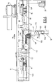
- Figures 1 and 2 show two usual filter presses, indicated by 100 and 101 respectively, which comprise a horizontally extending base frame 1, a plurality of identical vertical plates 2 mounted slidable along the frame longitudinal axis, a fixed head 3 and a movable head 4 operated by a cylinder-piston unit 5 and arranged to clamp said plates 2 together into a pack against said fixed head 3.
- the filter press 100 is provided with a unit (not shown) for detaching the plates 2 one at a time from the pack (to the left in Figure 1) to create at any given time a space A, whereas in the filter press 101 the plates 2 are connected together, for example by two opposing lateral chains, so that if the movable head 4 is completely retracted all the plates 2 are separated, with the creation of spaces B.
- the plate shifter unit for the filter press 100 is indicated by way of schematic example and can be modified to facilitate the operation of the invention.
- said plates 2 have their opposing faces recessed, respective filter cloths 6 being associated with said recessed faces as stated in the introduction.
- the invention is associated with the filter press 100 or 101 via two flat vertical structures 7 which are fixed to the longitudinal members of the frame 1. At the top of said structures 7 there are two travel tracks 8 for a carriage 9, this latter being driven by a geared motor unit 10.
- said carriage 9 is arranged to undergo outward travel (from right to left in Figures 1 and 2) with stepwise movement, whereas its return travel is effected with continuous movement.
- said carriage 9 is halted at each step under the control of a sensing device 11 which is positioned below the carriage 9 and is arranged to intercept corresponding lateral counteracting members 111 provided on the plates 2 (see Figure 3).
- This latter is coupled to a chain 130 passing endlessly about two sprockets 14 and 15 of vertical axis, the second 15 of which is driven by a geared motor unit 16.
- Said unit 16 is fixed to the carriage 9, and is of the type comprising a variable speed gear to enable the travelling speed of the carriage 13 to be selected as necessary.
- outward and return portions of the chain 130 are connected to respective support and slide guides, one of said portions being coupled to the carriage 13 via a descending peg 131.
- Said peg 131 is received within a slotted aperture 132 formed in a block 133 rigid with the carriage and positioned transversely to its sliding direction (Figure 5).
- the carriage 13 extends below the flat bars 12, where it comprises a fork-shaped member 17.
- a sprayer element 18 is hinged to said member 17 on an axis 170 transverse to the sliding direction of the carriage 13.
- the element 18 comprises, in proximity to said member 17, a highpressure rotatable connector 182 to which a hose 19 is connected via suitable valve means.
- the hose is connected to a pumping unit (not shown) able to feed a suitable pressurized wash liquid to the element 18.
- Said sprayer element 18 consists of a relatively thin hollow body of length such as to reach the lower edge of the plates 2 when it is positioned vertically.
- the sprayer element 18 shown in Figure 6 and typically for filter presses of the type shown in Figure 2, comprises a bar 180, for example cylindrical, with an outer diameter of 3 cm or a little more.
- a bar 180 for example cylindrical, with an outer diameter of 3 cm or a little more.
- Said nozzles 181 are sized such that those spray jets leaving them towards the same side of the bar are partly superimposed as shown in Figure 6, for obvious reasons.
- nozzles 181 are contained within the transverse outline of the bar 180.
- the sprayer element 18 shown in Figure 7 and typically for filter presses of the type shown in Figure 1, comprises two mutually parallel bars 180 each provided with a longitudinal series of equidistant nozzles 181, the delivery ports of one series being orientated towards the ports of the opposing series.
- the two bars 180 lie in a plane passing through their hinging axis 170 and are spaced apart in such a manner as to be able to embrace a plate 2.
- suitable spray shields such as transparent sheets are associated with the carriage 9 and frame 1.
- wash plant of the invention is controlled by a processor which enables the frequency with which the cycle is performed and the various cycle stages to be controlled as desired.
- the operation of the plant typically for filter presses 101 is as follows.
- the plates 2 are firstly spaced apart as shown in Figure 2 after closing the feed of the material to be filtered.
- the carriage 9 halts when the device 11 intercepts the first counteracting member 111, where the element 18 lies above the first space B in the open filter press.
- the carriage 13 undergoes a complete outward/return stroke, and is halted in its initial position by the effect of the sensor 99 which at the same time emits an enabling signal for the subsequent operation of the geared motor 10.
- the sensor 88 emits a signal for the purpose of closing the feed to this latter.
Landscapes
- Chemical & Material Sciences (AREA)
- Chemical Kinetics & Catalysis (AREA)
- Filtration Of Liquid (AREA)
Applications Claiming Priority (2)
| Application Number | Priority Date | Filing Date | Title |
|---|---|---|---|
| ITRE920080 | 1992-11-10 | ||
| ITRE920080A IT1257507B (it) | 1992-11-10 | 1992-11-10 | Impianto per il lavaggio automatico di filtropresse a piastre |
Publications (2)
| Publication Number | Publication Date |
|---|---|
| EP0597518A1 true EP0597518A1 (fr) | 1994-05-18 |
| EP0597518B1 EP0597518B1 (fr) | 1998-06-17 |
Family
ID=11398282
Family Applications (1)
| Application Number | Title | Priority Date | Filing Date |
|---|---|---|---|
| EP93202986A Expired - Lifetime EP0597518B1 (fr) | 1992-11-10 | 1993-10-26 | Installation pour le nettoyage automatique de filtre-presses à plateaux |
Country Status (4)
| Country | Link |
|---|---|
| EP (1) | EP0597518B1 (fr) |
| DE (1) | DE69319206T2 (fr) |
| ES (1) | ES2117692T3 (fr) |
| IT (1) | IT1257507B (fr) |
Cited By (1)
| Publication number | Priority date | Publication date | Assignee | Title |
|---|---|---|---|---|
| CN112915601A (zh) * | 2021-04-13 | 2021-06-08 | 肖炳衡 | 一种压滤机水冲洗装置 |
Families Citing this family (2)
| Publication number | Priority date | Publication date | Assignee | Title |
|---|---|---|---|---|
| ES2164516B1 (es) * | 1999-02-03 | 2003-10-16 | Talleres Landaluce S A | Dispositivo de lavado automatico de telas filtrantes. |
| CN114146460B (zh) * | 2021-12-21 | 2022-05-31 | 湖北亚星电子材料有限公司 | 一种多功能高效隔膜过滤机 |
Citations (3)
| Publication number | Priority date | Publication date | Assignee | Title |
|---|---|---|---|---|
| GB2046117A (en) * | 1979-04-05 | 1980-11-12 | Ishigaki Mech Ind | Apparatus for removing filter cake in a filter press |
| EP0307772A2 (fr) * | 1987-09-18 | 1989-03-22 | RITTERSHAUS & BLECHER GMBH | Filtre presse et dispositif de pulvérisation pour les plaques filtrantes |
| GB2227184A (en) * | 1989-01-19 | 1990-07-25 | Coal Ind | Filter press cloth washing devices |
Family Cites Families (2)
| Publication number | Priority date | Publication date | Assignee | Title |
|---|---|---|---|---|
| FR1394236A (fr) * | 1964-02-20 | 1965-04-02 | Paul Meura | Dispositif automatique de translation des cadres et plateaux de filtres-presses |
| CH602158A5 (en) * | 1976-12-14 | 1978-07-31 | Von Roll Ag | Filter press with movable cleaning appts. |
-
1992
- 1992-11-10 IT ITRE920080A patent/IT1257507B/it active IP Right Grant
-
1993
- 1993-10-26 EP EP93202986A patent/EP0597518B1/fr not_active Expired - Lifetime
- 1993-10-26 ES ES93202986T patent/ES2117692T3/es not_active Expired - Lifetime
- 1993-10-26 DE DE69319206T patent/DE69319206T2/de not_active Expired - Fee Related
Patent Citations (3)
| Publication number | Priority date | Publication date | Assignee | Title |
|---|---|---|---|---|
| GB2046117A (en) * | 1979-04-05 | 1980-11-12 | Ishigaki Mech Ind | Apparatus for removing filter cake in a filter press |
| EP0307772A2 (fr) * | 1987-09-18 | 1989-03-22 | RITTERSHAUS & BLECHER GMBH | Filtre presse et dispositif de pulvérisation pour les plaques filtrantes |
| GB2227184A (en) * | 1989-01-19 | 1990-07-25 | Coal Ind | Filter press cloth washing devices |
Cited By (1)
| Publication number | Priority date | Publication date | Assignee | Title |
|---|---|---|---|---|
| CN112915601A (zh) * | 2021-04-13 | 2021-06-08 | 肖炳衡 | 一种压滤机水冲洗装置 |
Also Published As
| Publication number | Publication date |
|---|---|
| ITRE920080A0 (it) | 1992-11-10 |
| DE69319206T2 (de) | 1998-10-15 |
| EP0597518B1 (fr) | 1998-06-17 |
| DE69319206D1 (de) | 1998-07-23 |
| ITRE920080A1 (it) | 1994-05-10 |
| ES2117692T3 (es) | 1998-08-16 |
| IT1257507B (it) | 1996-01-25 |
Similar Documents
| Publication | Publication Date | Title |
|---|---|---|
| US3608734A (en) | Liquid filtering apparatus | |
| JPS608843B2 (ja) | プレ−トフイルタ−プレス用の洗浄装置 | |
| US4129137A (en) | Washing apparatus for filter press | |
| EP4466081B1 (fr) | Filtre-presse amélioré | |
| KR102193514B1 (ko) | 필터프레스 탈수기용 안전장치 | |
| CA1176992A (fr) | Filtre-presse du type a plaques avec racloir | |
| US4659465A (en) | Washing apparatus for filter presses | |
| US4448221A (en) | Spraying apparatus for cleaning filter plates | |
| EP0597518B1 (fr) | Installation pour le nettoyage automatique de filtre-presses à plateaux | |
| FI78843B (fi) | Foerfarande foer rengoering av filtertyget i ett kammarfilter samt kammarfilter enligt foerfarandet. | |
| CN110694316A (zh) | 压滤机 | |
| US4584100A (en) | Filter press comprising means for filtering mud | |
| US3486624A (en) | Washing apparatus for washing the filter cloths in a filter press | |
| KR20010055350A (ko) | 필터프레스의 여과판 분리장치 | |
| KR19990066951A (ko) | 중량 감응식 여과판 충격장치를 구비한 필터 프레스 | |
| CA1320913C (fr) | Appareil permettant de deplacer et de laver les plaques filtrantes dans un filtre-presse | |
| DE3608774A1 (de) | Filterpresse | |
| US2839970A (en) | Screen cleaner | |
| JP3161358B2 (ja) | フィルタプレスのろ布洗浄装置 | |
| EP3065840B1 (fr) | Appareil de lavage de toile de filtration dans un filtre-presse | |
| CN117046203A (zh) | 水平过滤设备和用于水平过滤设备的排放装置和方法 | |
| AT393687B (de) | Vorrichtung zum reinigen der tueren von koksofenbatterien | |
| CA2235404C (fr) | Presse a filtres avec cognement sensible au poids des plaques de filtration | |
| GB2185904A (en) | A cleaning device for a filter press | |
| CH602158A5 (en) | Filter press with movable cleaning appts. |
Legal Events
| Date | Code | Title | Description |
|---|---|---|---|
| PUAI | Public reference made under article 153(3) epc to a published international application that has entered the european phase |
Free format text: ORIGINAL CODE: 0009012 |
|
| AK | Designated contracting states |
Kind code of ref document: A1 Designated state(s): DE ES FR GB IT |
|
| 17P | Request for examination filed |
Effective date: 19941012 |
|
| 17Q | First examination report despatched |
Effective date: 19951218 |
|
| GRAG | Despatch of communication of intention to grant |
Free format text: ORIGINAL CODE: EPIDOS AGRA |
|
| GRAG | Despatch of communication of intention to grant |
Free format text: ORIGINAL CODE: EPIDOS AGRA |
|
| GRAH | Despatch of communication of intention to grant a patent |
Free format text: ORIGINAL CODE: EPIDOS IGRA |
|
| GRAH | Despatch of communication of intention to grant a patent |
Free format text: ORIGINAL CODE: EPIDOS IGRA |
|
| GRAA | (expected) grant |
Free format text: ORIGINAL CODE: 0009210 |
|
| AK | Designated contracting states |
Kind code of ref document: B1 Designated state(s): DE ES FR GB IT |
|
| REF | Corresponds to: |
Ref document number: 69319206 Country of ref document: DE Date of ref document: 19980723 |
|
| ET | Fr: translation filed | ||
| REG | Reference to a national code |
Ref country code: ES Ref legal event code: FG2A Ref document number: 2117692 Country of ref document: ES Kind code of ref document: T3 |
|
| PLBE | No opposition filed within time limit |
Free format text: ORIGINAL CODE: 0009261 |
|
| 26N | No opposition filed | ||
| REG | Reference to a national code |
Ref country code: GB Ref legal event code: IF02 |
|
| PGFP | Annual fee paid to national office [announced via postgrant information from national office to epo] |
Ref country code: ES Payment date: 20041006 Year of fee payment: 12 |
|
| PGFP | Annual fee paid to national office [announced via postgrant information from national office to epo] |
Ref country code: DE Payment date: 20041008 Year of fee payment: 12 |
|
| PGFP | Annual fee paid to national office [announced via postgrant information from national office to epo] |
Ref country code: FR Payment date: 20041026 Year of fee payment: 12 |
|
| PGFP | Annual fee paid to national office [announced via postgrant information from national office to epo] |
Ref country code: GB Payment date: 20041028 Year of fee payment: 12 |
|
| PG25 | Lapsed in a contracting state [announced via postgrant information from national office to epo] |
Ref country code: IT Free format text: LAPSE BECAUSE OF NON-PAYMENT OF DUE FEES Effective date: 20051026 Ref country code: GB Free format text: LAPSE BECAUSE OF NON-PAYMENT OF DUE FEES Effective date: 20051026 |
|
| PG25 | Lapsed in a contracting state [announced via postgrant information from national office to epo] |
Ref country code: ES Free format text: LAPSE BECAUSE OF NON-PAYMENT OF DUE FEES Effective date: 20051027 |
|
| PG25 | Lapsed in a contracting state [announced via postgrant information from national office to epo] |
Ref country code: DE Free format text: LAPSE BECAUSE OF NON-PAYMENT OF DUE FEES Effective date: 20060503 |
|
| GBPC | Gb: european patent ceased through non-payment of renewal fee |
Effective date: 20051026 |
|
| PG25 | Lapsed in a contracting state [announced via postgrant information from national office to epo] |
Ref country code: FR Free format text: LAPSE BECAUSE OF NON-PAYMENT OF DUE FEES Effective date: 20060630 |
|
| REG | Reference to a national code |
Ref country code: FR Ref legal event code: ST Effective date: 20060630 |
|
| REG | Reference to a national code |
Ref country code: ES Ref legal event code: FD2A Effective date: 20051027 |