EP0597619A1 - Distributeur d'air pour une vitesse d'air uniforme - Google Patents
Distributeur d'air pour une vitesse d'air uniforme Download PDFInfo
- Publication number
- EP0597619A1 EP0597619A1 EP93308753A EP93308753A EP0597619A1 EP 0597619 A1 EP0597619 A1 EP 0597619A1 EP 93308753 A EP93308753 A EP 93308753A EP 93308753 A EP93308753 A EP 93308753A EP 0597619 A1 EP0597619 A1 EP 0597619A1
- Authority
- EP
- European Patent Office
- Prior art keywords
- manifold
- air flow
- housing
- inlet
- duct
- Prior art date
- Legal status (The legal status is an assumption and is not a legal conclusion. Google has not performed a legal analysis and makes no representation as to the accuracy of the status listed.)
- Granted
Links
Images


Classifications
-
- G—PHYSICS
- G03—PHOTOGRAPHY; CINEMATOGRAPHY; ANALOGOUS TECHNIQUES USING WAVES OTHER THAN OPTICAL WAVES; ELECTROGRAPHY; HOLOGRAPHY
- G03G—ELECTROGRAPHY; ELECTROPHOTOGRAPHY; MAGNETOGRAPHY
- G03G21/00—Arrangements not provided for by groups G03G13/00 - G03G19/00, e.g. cleaning, elimination of residual charge
- G03G21/0005—Arrangements not provided for by groups G03G13/00 - G03G19/00, e.g. cleaning, elimination of residual charge for removing solid developer or debris from the electrographic recording medium
- G03G21/0035—Arrangements not provided for by groups G03G13/00 - G03G19/00, e.g. cleaning, elimination of residual charge for removing solid developer or debris from the electrographic recording medium using a brush; Details of cleaning brushes, e.g. fibre density
-
- G—PHYSICS
- G03—PHOTOGRAPHY; CINEMATOGRAPHY; ANALOGOUS TECHNIQUES USING WAVES OTHER THAN OPTICAL WAVES; ELECTROGRAPHY; HOLOGRAPHY
- G03G—ELECTROGRAPHY; ELECTROPHOTOGRAPHY; MAGNETOGRAPHY
- G03G21/00—Arrangements not provided for by groups G03G13/00 - G03G19/00, e.g. cleaning, elimination of residual charge
- G03G21/0005—Arrangements not provided for by groups G03G13/00 - G03G19/00, e.g. cleaning, elimination of residual charge for removing solid developer or debris from the electrographic recording medium
- G03G21/0052—Arrangements not provided for by groups G03G13/00 - G03G19/00, e.g. cleaning, elimination of residual charge for removing solid developer or debris from the electrographic recording medium using an air flow; Details thereof, e.g. nozzle structure
-
- G—PHYSICS
- G03—PHOTOGRAPHY; CINEMATOGRAPHY; ANALOGOUS TECHNIQUES USING WAVES OTHER THAN OPTICAL WAVES; ELECTROGRAPHY; HOLOGRAPHY
- G03G—ELECTROGRAPHY; ELECTROPHOTOGRAPHY; MAGNETOGRAPHY
- G03G2221/00—Processes not provided for by group G03G2215/00, e.g. cleaning or residual charge elimination
- G03G2221/0005—Cleaning of residual toner
Definitions
- This invention relates generally to an elec- trostatographic copier or printer, and more particularly, concerns a cleaning apparatus using uniform air velocity.
- a charge retentive surface i.e., photoconductor, photoreceptor or imaging surface
- the resulting pattern of charged and discharged areas on that surface form an electrostatic charge pattern (an electrostatic latent image) conforming to the original image.
- the latent image is developed by contacting it with a finely divided electrostatically attractable powder referred to as "toner". Toner is held on the image areas by the electrostatic charge on the surface.
- a toner image is produced in conformity with a light image of the original being reproduced.
- the toner image may then be transferred to a substrate (e.g., paper), and the image affixed thereto to form a permanent record of the image to be reproduced.
- a substrate e.g., paper
- excess toner left on the charge retentive surface is cleaned from the surface.
- Ion projection devices where a charge is imagewise deposited on a charge retentive substrate operate similarly.
- a commercially successful mode of cleaning employed on automatic xerographic devices utilizes a brush with soft conductive fiber bristles or with insulative soft bristles which have suitable triboelectric characteristics. While the bristles are soft for the insulative brush, they provide sufficient mechanical force to dislodge residual toner particles from the charge retentive surface.
- the brush In the case of the conductive brush, the brush is usually electrically biased to provide an electrostatic force for toner detachment from the charge retentive surface. Toner particles adhere to the fibers (i.e. bristles) of the brush after the charge retentive surface has been cleaned.
- the process of removing toner from these types of cleaner brushes can be accomplished in many ways. Typically, brush cleaners, use flicker bars to provide the detoning function.
- rotary brush cleaners also encounter problems with photoreceptor filming and abrasion, and toner emissions.
- the filming and abrasion are due to the high impact forces that result when the brush fibers strike the toner and photoreceptor.
- Toner emissions usually result from inadequate or non-uniform air flow entering the cleaner at the housing to photoreceptor gaps.
- High velocity air streams have been used to clean photoreceptors in the past.
- Photoreceptors and BTRs have used air knives to create a high velocity air stream to clean their surfaces.
- Such devices can consist of a plate, closely spaced to the surface to be cleaned, with narrow slots cut into it.
- a vacuum is applied behind the plate to cause air to flow through the slots and create a high velocity airstream across the surface being cleaned.
- the high velocity air flow disturbs the surface boundary layer allowing removal of particles adhered to the surface.
- the problems with this approach are in the manufacture of the device and the power required to create the vacuum.
- the tolerances for the cleaner and the surface to be cleaned must be held closely.
- the orifice slot width must be uniform along its length to maintain uniform air velocities and therefore cleaning.
- the spacing between the plate and surface to be cleaned must also be uniform for the same reasons. This requires the plate and cleaning surface to be straight, flat and well aligned. If the surface to be cleaned is a roll, the runout of the roll and the parallelism of the roll axis to the slot axis is also important. Because of the close spacing of the cleaning plate to the surface to be cleaned and the narrow orifice slot, the resistance of the system to air flow is very high. As a result of this high resistance to air flow, a considerable air flow is required to generate the required cleaning air velocities needed for the narrow orifice slot to clean the surface. The requirements of high pressure and air flow result in a high power usage for the system and the possibility of a noise problem.
- toner In practice, toner often times is not completely removed from the chamber of the cleaning apparatus due to uneven air flow over the length of the brush and within the chamber. This uneven air flow causes nonuniform cleaning of the rotating brush and results in deposition of the toner in areas of the chamber where the air flow velocity becomes too low to transport toner. Eventually, air flow and cleaning efficiency can be reduced to a point where residual toner material is left on the photoconductive member and is transferred to subsequent receiver sheets resulting in copies with ghost images or high density background.
- US-A-4,459,012 to Allen et al. discloses a cleaning apparatus having a manifold housing which partially encloses a rotating brush.
- a chamber, defined by the manifold housing, has a plurality of air flow dividers disposed therein forming channels extending from a position spaced near the brush into an outlet port which is coupled to a vacuum source. These channels direct air flow across the cleaner brush to remove toner therefrom.
- US-A-4,809,035 to Allen, Jr. discloses an apparatus for separating and removing non-magnetic lubricating particles.
- An air manifold assembly having a blower, is mounted on the toner unit housing, of the unwanted particle chamber, to draw the unwanted particles from such chamber.
- US-A-3,793,986 to Latone discloses a toner powder reclaiming system for use in conjunction with a photoreceptor cleaning device.
- the system includes a particle separator in the path of movement of air flow containing toner particles from a brush cleaning device.
- the toner particles are separated from cleaning debris particles and conveyed to a collection manifold and thence to collecting containers.
- the object of the present invention is to provide an improved apparatus for removing particles from a surface. Accordingly, the present invention provides an apparatus according to any one of the appended claims.
- an apparatus for removing particles from a surface includes a housing and a cleaning means at least partially enclosed in the housing, for dislodging toner particles from the surface.
- Manifold means connected to the housing, for creating a uniform air flow.
- Vacuum means connected to said manifold for generating air flow through said manifold.
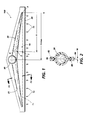
- FIG. 1 shows a schematic elevational view of the uniform air flow manifold.
- the uniform air flow section of the manifold has three regions. The first is the triangular inlet region or narrow gap region 10. This is a narrow constant gap slot having uniform, constant velocity, and parallel air flow streams through it.
- the base of the triangular inlet region 10 is indicated by an imaginary line, L i , drawn from the opposing end points of the second region called the collection duct 20.
- the collection duct 20 is located just above the triangular inlet region 10.
- the bent architecture of the collection duct 20 forms the top two diagonal sides of the triangular inlet region 10.
- the collection duct 20 (shown here as a circular cross-section duct) collects air flow exiting the triangular inlet region 10 and transports the collected air flow to a third region, the exhaust duct 30.
- the preferred embodiment of the exhaust duct 30 in the invention is for the exhaust duct 30 to be centrally located near the apex of the triangular configuration of the manifold 100 and, partially on the collection ducts 20 where they meet.
- the collection duct region is chosen as a convenient cross-sectional shape, eg., circular, rectangular or square. The lowest drag cross-section is circular.
- the air flow entering the manifold into the narrow constant gap region is designed to be uniform, as shown by the arrows 15.
- the air flow is parallel through the narrow gap region 10 until it enters the collection duct 20.
- the collection duct 20 collects the flows from the narrow gap region 10 and directs them to the exhaust duct 30 at the peak of the triangular narrow gap region 10.
- the exhaust duct 30 is connected by a hose to the air system.
- the velocities at the inlet slot 50 remain uniform because the collection duct 20 diameters are chosen such that the pressure drops for all air streams passing through any cross-section of the collection duct 20 are equal at a constant inlet velocity.
- Points 1-4 are included in this figure, where point 1 is a point along L 1 at the inlet of the triangular narrow gap region 10 of the manifold 100, at some distance between 0 and X max .
- Point 2 is located directly above point 1 at the intersection of the triangular narrow gap region 10 and the collection duct 20.
- Point 3 is the end point at the edge of the collection duct 20 at location 0.
- Point 4 is a point along a plane perpendicular to the air flow through the collection duct and adjacent to point 2, where the pressure is assumed constant along the plane.
- the velocity remains constant through the narrow gap region 10, point 1 to point 2, at location X, where X is the distance along the manifold inlet, from 0 to the center point of the exhaust duct, X max .
- the pressure drop experienced by this flow is fairly easily estimated as a constant velocity air flow through a constant gap channel of the length from point 1 to point 2.
- the air flow exits the narrow gap region at point 2 and joins the cumulative air flow at point 4.
- the flow at point 4 is the sum of the air flows entering the inlet between point 1 and point 3.
- the pressure drop of the air flow traveling from point 3 to point 4 must match the pressure drop from point 1 to point 2.
- the collection duct 20 air flow increases linearly from the ends due to the uniform inlet velocity in accordance with the equation:
- Q x V lNLET x gap x X.
- V INLET the inlet velocity
- gap refers to the distance between the front half of the manifold and the second half of the manifold (see the cross section of the inlet area, dimension W, in Figure 2) and is the distance along the inlet from 0 to X max .] Since the pressure drop is proportional to the path length (i.e the path length from point 3 to point 4) and the path length increases linearly from the edges of the triangular inlet region 10 to the center, then the pressure drop increases linearly from zero at the edges to a maximum at the center of the manifold.
- the velocity remains constant on the other half of the manifold in a similar manner as that just described. Therefore, the pressure drop and flow required for uniform inlet flow is known at all collection duct 20 locations, X. From this information it is possible to compute the collection duct diameters which will result in the required pressure drops at the specified air flows for all locations, X. When these relationships hold at all locations, X, then a manifold with a uniform inlet air flow will result.
- the exhaust duct 30 diameter is chosen to result in an area equal to the converging areas of the left side of the manifold and the right side of the manifold collection ducts 20.
- the manifold 100 is designed by specifying the center height (H CTR , see Figure 9) of the narrow gap region 10, the narrow gap region gap width (W, see Figure 2), the collection duct 20 cross-sectional shape and either the total air flow through the manifold 100 or the inlet velocity 15.
- the collection duct size can then be calculated and the inlet velocity, collection duct velocity, total air flow and pressure drop for the manifold 100 found.
- An acceptable design must fit into the available space, have narrow gap and duct velocities high enough to prevent blocking (preferably greater than 50 ft/sec) and have pressure/flow characteristics which are compatible with the air system and machine power requirements.
- Manifolds may be designed to give uniform inlet air flow for a wide range of manifold heights.
- the space available for the manifold is at least roughly known. This will put a limit on the allowable height of the triangular narrow gap region 10, the collection duct 20 and the exhaust duct 30.
- the height of the narrow gap region 10 may be tentatively chosen, the collection duct size calculated and the exhaust duct diameter added to determine the total manifold height. If this resulting height is too large, a smaller height is then chosen, a new manifold height calculated, and the process repeated until an acceptable height is found. Very short manifold designs are possible but at the cost of increasing manifold pressure drop.
- FIG 2 shows section F2 of Figure 1.
- the figure shows the cross-section of the circular collection duct 20.
- the width, W, of the inlet opening between the manifold walls through the narrow gap region is shown.
- Spacers 84 and nodules 89 maintain the opening of the narrow gap region when air flows therethrough.
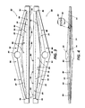
- FIG. 3 shows the front and back halves of the manifold.
- the front half 80 contains receiving holes 82 along one diagonal side of the manifold and pegs 86 along the other diagonal side of the front half of the manifold.
- the back half 90 contains receiving holes 92 along the diagonal side of the manifold opposite the pegs 86 in the front half 80 of the manifold and the back half 90 contains pegs 96 along the diagonal side of the manifold opposite the receiving holes 82 of the front half 80 so that the two halves 80, 90 can be interconnected and aligned by the respective pegs 86, 96 in the appropriate receiving holes 82, 92. (See Fig.
- both the front 80 and back 90 halves of the manifold contain relief elements called spacers 84, 94 to maintain the narrow inlet slot 50 when the manifold halves are connected together and a vacuum is applied to the manifold.
- One half of the base of the front half 80 of the manifold contains spacers 84 and the opposite half side of the base of the back half 90 of the manifold contains spacers 94 such that when both halves are connected together the base of the manifold has spacers along the entire length of the base. All of these spacers are of a small enough size that minimal disruption to the air flow through the manifold is experienced.
- nodules 99 are placed on the back inner wall surface of the manifold and nodules 89 are placed on the front inner wall surface of the manifold.
- FIG 4 shows the inlet gap of the manifold.
- the inlet slot or gap 50 has an opening (shown as w in Figure 2) whose width is maintained by spacers 84, 94 as air flows through the manifold.
- An enlargement of a section of the inlet slot 50 having a spacer 94 therebetween is shown.
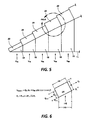
- Figure 5 is a diagrammatic view of a portion of the triangular inlet region for calculating air flow.
- Each calculation interval is assumed to be a constant cross-section, circular duct with diameter d, and change in length AS (see Figure 6), with pressures, flows and velocities calculated at the right side of the duct section.
- the number of pipe sections is not limited to 25, the number can be greater or smaller.
- Q is the air flow rate through pipe section "i" (i.e. 1 to 25) and is determined by the product of V IN ⁇ G-(i)(t) where V IN is the uniform inlet velocity, AG is the width of each of the manifold pipe sections, "i” is the number of separate pipe sections (i.e. 1 to 25) and "t" is the gap size of the inlet.
- Figure 6 also shows AQ which indicates a change in the air flow rate of the duct pipe section from Q i-1 : the air flow rate entering the duct pipe, to Q ; : the air flow rate exiting the duct pipe section.
- the change in pipe section duct diameter is indicated in a similar manner in Figure 6 by the variables d i-1 and d i .
- FIG 7 shows how the manifold can be attached to a cleaner housing.
- the two manifolds are attached to each other by a connecting device 180.
- the brush cleaners 120 rotate in the direction of arrow 121.
- the brush fibers 190 impact against the photoreceptive surface 17 to clean the surface of residual particles.
- the photoreceptive surface moves in the direction of arrow 16.
- An enlargement of the brush fiber 190 shows it's cylindrical surface 191 which is one of the surfaces the present invention can be used to clean.
- the cleaning device does not have to be a brush cleaner, it can be a blade or an air knife or any other cleaning mechanism to which the manifold 100 can be attached to clean an imaging surface.
- FIG 8 shows another embodiment of the present invention in which the manifold 101 is wrapped around the cylindrical cleaner housing.
- the two piece straight manifold 100 (shown in Figure 7) becomes a single molded piece manifold 101 which is attached to the cleaner housing 130 which becomes the second side of the manifold.
- the inlet gap region 140 is curved such that the air inlet flow path length is the same as it was for the straight manifold.
- the collection duct region 150 diameters are shifted to the molded piece side of the manifold.
- This modified manifold would be expected to have slightly higher pressure losses than the straight manifold due to the curved flow path, but significant reductions in space of the total assembly are possible. Since the modified manifold 101 uses the cleaner housing as one of its walls, the problem of aligning the manifold inlet slot to a matching slot in the cleaner housing is eliminated.
- FIG 9 shows yet another embodiment of the present invention in which the manifold exhaust duct 30 is located off center.
- each side of the manifold from an edge to the exhaust duct 30 is treated separately as though it were half of a shorter centered manifold, Figure 10, and half of a longer centered manifold Figure 11.
- the left side of the manifold is shown as the shorter side of the manifold.
- Figure 10 shows how to calculate O lelt which is the air flow through the collection duct 30 on the left side by taking the product of the variables: L ieft (length of Li, the bottom of the triangular inlet region 10 from the left edge to the middle of the exhaust duct 30), inlet gap (distance between the front and back manifold in the narrow gap region 10), and V INLET (the inlet velocity).
- L ieft length of Li, the bottom of the triangular inlet region 10 from the left edge to the middle of the exhaust duct 30
- inlet gap distance between the front and back manifold in the narrow gap region 10
- V INLET the inlet velocity
- the apparatus for removing particles from a surface utilizes a manifold having three regions.
- the three regions include a triangular inlet region, a collection duct region and an exhaust duct region.
- the triangular inlet includes a narrow constant gap slot along the length of the manifold through which a stream of parallel air flows through uniformly.
- the collection duct is adjacent to the triangular inlet and collects the air flow exiting from the triangular inlet.
- the exhaust duct in it's preferred embodiment, is centrally located at the apex of the triangular manifold, partially situated on the collection ducts where they meet.
- the exhaust duct provides an exit for the air being transported by the collection ducts.
- the combination of these three regions provide uniform air flow velocity through the manifold.
Landscapes
- Physics & Mathematics (AREA)
- General Physics & Mathematics (AREA)
- Cleaning In Electrography (AREA)
- Control Or Security For Electrophotography (AREA)
Applications Claiming Priority (2)
| Application Number | Priority Date | Filing Date | Title |
|---|---|---|---|
| US07/976,035 US5268727A (en) | 1992-11-13 | 1992-11-13 | Uniform velocity air manifold |
| US976035 | 1992-11-13 |
Publications (2)
| Publication Number | Publication Date |
|---|---|
| EP0597619A1 true EP0597619A1 (fr) | 1994-05-18 |
| EP0597619B1 EP0597619B1 (fr) | 1997-08-13 |
Family
ID=25523649
Family Applications (1)
| Application Number | Title | Priority Date | Filing Date |
|---|---|---|---|
| EP93308753A Expired - Lifetime EP0597619B1 (fr) | 1992-11-13 | 1993-11-02 | Distributeur d'air pour une vitesse d'air uniforme |
Country Status (6)
| Country | Link |
|---|---|
| US (1) | US5268727A (fr) |
| EP (1) | EP0597619B1 (fr) |
| JP (1) | JP2641685B2 (fr) |
| BR (1) | BR9304717A (fr) |
| DE (1) | DE69313076T2 (fr) |
| MX (1) | MX9306664A (fr) |
Families Citing this family (7)
| Publication number | Priority date | Publication date | Assignee | Title |
|---|---|---|---|---|
| US5678160A (en) * | 1996-01-16 | 1997-10-14 | Lexmark International, Inc. | Envelope printing |
| US5799227A (en) * | 1996-06-06 | 1998-08-25 | Moore Business Forms, Inc. | Non-magnetic toner dynamic recycling |
| US7266323B2 (en) * | 2005-04-21 | 2007-09-04 | Xerox Corporation | Manifold for toner collection and contamination control in xerographic process developer housing |
| US7512357B2 (en) * | 2005-08-22 | 2009-03-31 | Xerox Corporation | Image forming device arranged with plural particle removal devices |
| ES2263394B1 (es) * | 2006-02-01 | 2007-11-16 | Sener, Ingenieria Y Sistemas, S.A. | Colector de seccion transversal variable y pared delgada para paneles de absorcion solar. |
| DE102012011328A1 (de) * | 2012-06-06 | 2013-12-12 | Linde Aktiengesellschaft | Wärmeübertrager |
| US10639653B1 (en) | 2017-02-09 | 2020-05-05 | AirBTU, Inc. | Air outlet device |
Citations (9)
| Publication number | Priority date | Publication date | Assignee | Title |
|---|---|---|---|---|
| US3703957A (en) * | 1968-03-06 | 1972-11-28 | Kenneth W Swanson | Pneumatic separator, filter and particle conveying system |
| US4014065A (en) * | 1975-08-27 | 1977-03-29 | Xerox Corporation | Magnetic developer removal system |
| US4111546A (en) * | 1976-08-26 | 1978-09-05 | Xerox Corporation | Ultrasonic cleaning apparatus for an electrostatographic reproducing machine |
| US4113376A (en) * | 1977-05-25 | 1978-09-12 | Xerox Corporation | Cleaning apparatus for reproducing machine |
| EP0100246A1 (fr) * | 1982-07-22 | 1984-02-08 | COMPAGNIE INTERNATIONALE POUR L'INFORMATIQUE CII - HONEYWELL BULL (dite CII-HB) | Dispositif pour retirer les particules de révélateur en excès sur la surface d'un élément d'enregistrement |
| US4459012A (en) * | 1982-04-05 | 1984-07-10 | Eastman Kodak Company | Cleaning station air diverters |
| EP0320812A2 (fr) * | 1987-12-18 | 1989-06-21 | Fujitsu Limited | Unité de nettoyage pour le nettoyage de matériaux d'enregistrement d'un appareil électrophotographique |
| US4910560A (en) * | 1987-03-05 | 1990-03-20 | Minolta Camera Kabushiki Kaisha | Cleaning device for use in copying machine |
| US4989047A (en) * | 1989-12-11 | 1991-01-29 | Xerox Corporation | Cleaning apparatus for the reduction of agglomeration-caused spotting |
Family Cites Families (10)
| Publication number | Priority date | Publication date | Assignee | Title |
|---|---|---|---|---|
| US3708823A (en) * | 1969-03-03 | 1973-01-09 | B Bell | Street and parking lot cleaner attachment for vehicles |
| US3706108A (en) * | 1970-12-28 | 1972-12-19 | Eastman Kodak Co | Apparatus for cleaning a residual image from a photosensitive member |
| US3793986A (en) * | 1971-06-11 | 1974-02-26 | S Latone | Toner reclaiming system for electrostatic printing machines |
| US4435073A (en) * | 1982-08-16 | 1984-03-06 | Xerox Corporation | Toner removal apparatus |
| JPS60117359A (ja) * | 1983-11-30 | 1985-06-24 | Toshiba Corp | 情報処理システム |
| US4601569A (en) * | 1984-12-19 | 1986-07-22 | Eastman Kodak Company | Apparatus for cleaning a photoconductor |
| US4868599A (en) * | 1986-06-02 | 1989-09-19 | Seiko Epson Corporation | Device and method for storing toner waste |
| US4809035A (en) * | 1987-07-07 | 1989-02-28 | Allen Jr Joseph M | Ion deposition printer with improved toning unit assembly including apparatus for separating and removing non-magnetic lubricating particles |
| US4903084A (en) * | 1987-12-14 | 1990-02-20 | Eastman Kodak Company | Cleaning apparatus having an interference-fit housing |
| US4918488A (en) * | 1989-06-26 | 1990-04-17 | Eastman Kodak Company | Scavenging apparatus |
-
1992
- 1992-11-13 US US07/976,035 patent/US5268727A/en not_active Expired - Lifetime
-
1993
- 1993-06-28 JP JP5157717A patent/JP2641685B2/ja not_active Expired - Fee Related
- 1993-10-26 MX MX9306664A patent/MX9306664A/es not_active IP Right Cessation
- 1993-11-02 DE DE69313076T patent/DE69313076T2/de not_active Expired - Fee Related
- 1993-11-02 EP EP93308753A patent/EP0597619B1/fr not_active Expired - Lifetime
- 1993-11-12 BR BR9304717A patent/BR9304717A/pt not_active IP Right Cessation
Patent Citations (9)
| Publication number | Priority date | Publication date | Assignee | Title |
|---|---|---|---|---|
| US3703957A (en) * | 1968-03-06 | 1972-11-28 | Kenneth W Swanson | Pneumatic separator, filter and particle conveying system |
| US4014065A (en) * | 1975-08-27 | 1977-03-29 | Xerox Corporation | Magnetic developer removal system |
| US4111546A (en) * | 1976-08-26 | 1978-09-05 | Xerox Corporation | Ultrasonic cleaning apparatus for an electrostatographic reproducing machine |
| US4113376A (en) * | 1977-05-25 | 1978-09-12 | Xerox Corporation | Cleaning apparatus for reproducing machine |
| US4459012A (en) * | 1982-04-05 | 1984-07-10 | Eastman Kodak Company | Cleaning station air diverters |
| EP0100246A1 (fr) * | 1982-07-22 | 1984-02-08 | COMPAGNIE INTERNATIONALE POUR L'INFORMATIQUE CII - HONEYWELL BULL (dite CII-HB) | Dispositif pour retirer les particules de révélateur en excès sur la surface d'un élément d'enregistrement |
| US4910560A (en) * | 1987-03-05 | 1990-03-20 | Minolta Camera Kabushiki Kaisha | Cleaning device for use in copying machine |
| EP0320812A2 (fr) * | 1987-12-18 | 1989-06-21 | Fujitsu Limited | Unité de nettoyage pour le nettoyage de matériaux d'enregistrement d'un appareil électrophotographique |
| US4989047A (en) * | 1989-12-11 | 1991-01-29 | Xerox Corporation | Cleaning apparatus for the reduction of agglomeration-caused spotting |
Also Published As
| Publication number | Publication date |
|---|---|
| BR9304717A (pt) | 1994-05-17 |
| JP2641685B2 (ja) | 1997-08-20 |
| MX9306664A (es) | 1994-05-31 |
| DE69313076T2 (de) | 1998-02-12 |
| EP0597619B1 (fr) | 1997-08-13 |
| JPH06175548A (ja) | 1994-06-24 |
| US5268727A (en) | 1993-12-07 |
| DE69313076D1 (de) | 1997-09-18 |
Similar Documents
| Publication | Publication Date | Title |
|---|---|---|
| AU594594B2 (en) | Cleaning unit for cleaning recording medium of an electrophotographic apparatus | |
| EP0366426A1 (fr) | Dispositif électrophotographique avec un ensemble de nettoyage commandé à courant alternatif | |
| US4304026A (en) | Cleaning apparatus for a xerographic reproduction machine | |
| US4681426A (en) | Brush end seals for blade cleaner housing | |
| EP0103405B1 (fr) | Appareil pour enlever du toner | |
| EP0597619B1 (fr) | Distributeur d'air pour une vitesse d'air uniforme | |
| EP0621517B1 (fr) | Barre de détachement pour le nettoyage électrographique | |
| US4205911A (en) | Cleaning system | |
| EP0377705B1 (fr) | Appareil de nettoyage a profils aerodynamiques | |
| US5455666A (en) | Developer extracting apparatus and image forming apparatus using it | |
| US4459012A (en) | Cleaning station air diverters | |
| US5291628A (en) | High velocity air cleaner | |
| US5121167A (en) | Sweep and vacuum xerographic cleaning method and apparatus | |
| US4483611A (en) | Magnetic cleaning device | |
| US5923940A (en) | Cleaning brush having fibers of different lengths | |
| US6169872B1 (en) | Electrostatic cleaning belt brush | |
| US6754466B1 (en) | Toner removal apparatus for copier or printer | |
| JP4063903B2 (ja) | 像形成表面の磁性粒体の除去装置 | |
| JP3467943B2 (ja) | トナークラウド回収装置 | |
| EP1304602B1 (fr) | Dispositif d'enlevement de fibres pour appareil de formation d'image | |
| US5241352A (en) | Air detoned cleaner brush | |
| JPS6168152A (ja) | サイクロン分離器 | |
| JPS59172672A (ja) | フア−ブラシクリ−ニング装置 | |
| JPH055581Y2 (fr) | ||
| JPH0318713B2 (fr) |
Legal Events
| Date | Code | Title | Description |
|---|---|---|---|
| PUAI | Public reference made under article 153(3) epc to a published international application that has entered the european phase |
Free format text: ORIGINAL CODE: 0009012 |
|
| AK | Designated contracting states |
Kind code of ref document: A1 Designated state(s): DE FR GB |
|
| 17P | Request for examination filed |
Effective date: 19941109 |
|
| 17Q | First examination report despatched |
Effective date: 19960329 |
|
| GRAG | Despatch of communication of intention to grant |
Free format text: ORIGINAL CODE: EPIDOS AGRA |
|
| GRAH | Despatch of communication of intention to grant a patent |
Free format text: ORIGINAL CODE: EPIDOS IGRA |
|
| GRAH | Despatch of communication of intention to grant a patent |
Free format text: ORIGINAL CODE: EPIDOS IGRA |
|
| GRAA | (expected) grant |
Free format text: ORIGINAL CODE: 0009210 |
|
| AK | Designated contracting states |
Kind code of ref document: B1 Designated state(s): DE FR GB |
|
| REF | Corresponds to: |
Ref document number: 69313076 Country of ref document: DE Date of ref document: 19970918 |
|
| ET | Fr: translation filed | ||
| PLBE | No opposition filed within time limit |
Free format text: ORIGINAL CODE: 0009261 |
|
| 26N | No opposition filed | ||
| REG | Reference to a national code |
Ref country code: GB Ref legal event code: IF02 |
|
| PGFP | Annual fee paid to national office [announced via postgrant information from national office to epo] |
Ref country code: GB Payment date: 20041027 Year of fee payment: 12 |
|
| PGFP | Annual fee paid to national office [announced via postgrant information from national office to epo] |
Ref country code: DE Payment date: 20041028 Year of fee payment: 12 |
|
| PGFP | Annual fee paid to national office [announced via postgrant information from national office to epo] |
Ref country code: FR Payment date: 20050825 Year of fee payment: 13 |
|
| REG | Reference to a national code |
Ref country code: GB Ref legal event code: 746 Effective date: 20050809 |
|
| PG25 | Lapsed in a contracting state [announced via postgrant information from national office to epo] |
Ref country code: GB Free format text: LAPSE BECAUSE OF NON-PAYMENT OF DUE FEES Effective date: 20051102 |
|
| PG25 | Lapsed in a contracting state [announced via postgrant information from national office to epo] |
Ref country code: DE Free format text: LAPSE BECAUSE OF NON-PAYMENT OF DUE FEES Effective date: 20060601 |
|
| GBPC | Gb: european patent ceased through non-payment of renewal fee |
Effective date: 20051102 |
|
| REG | Reference to a national code |
Ref country code: FR Ref legal event code: ST Effective date: 20070731 |
|
| PG25 | Lapsed in a contracting state [announced via postgrant information from national office to epo] |
Ref country code: FR Free format text: LAPSE BECAUSE OF NON-PAYMENT OF DUE FEES Effective date: 20061130 |