EP0597628B1 - Système de réapprovisionnement en encre dans une imprimante par jet d'encre continu - Google Patents
Système de réapprovisionnement en encre dans une imprimante par jet d'encre continu Download PDFInfo
- Publication number
- EP0597628B1 EP0597628B1 EP19930308818 EP93308818A EP0597628B1 EP 0597628 B1 EP0597628 B1 EP 0597628B1 EP 19930308818 EP19930308818 EP 19930308818 EP 93308818 A EP93308818 A EP 93308818A EP 0597628 B1 EP0597628 B1 EP 0597628B1
- Authority
- EP
- European Patent Office
- Prior art keywords
- ink
- supply
- resistivity
- ink supply
- main
- Prior art date
- Legal status (The legal status is an assumption and is not a legal conclusion. Google has not performed a legal analysis and makes no representation as to the accuracy of the status listed.)
- Expired - Lifetime
Links
Images


Classifications
-
- B—PERFORMING OPERATIONS; TRANSPORTING
- B41—PRINTING; LINING MACHINES; TYPEWRITERS; STAMPS
- B41J—TYPEWRITERS; SELECTIVE PRINTING MECHANISMS, i.e. MECHANISMS PRINTING OTHERWISE THAN FROM A FORME; CORRECTION OF TYPOGRAPHICAL ERRORS
- B41J2/00—Typewriters or selective printing mechanisms characterised by the printing or marking process for which they are designed
- B41J2/005—Typewriters or selective printing mechanisms characterised by the printing or marking process for which they are designed characterised by bringing liquid or particles selectively into contact with a printing material
- B41J2/01—Ink jet
- B41J2/17—Ink jet characterised by ink handling
- B41J2/195—Ink jet characterised by ink handling for monitoring ink quality
Definitions
- the present invention relates to apparatus and methods for replenishing ink in a continuous ink jet printer.
- conductive ink which includes a carrier fluid such as water or an organic solvent and a colorant, such as a dye or pigment is continuously recirculated through the system to a print head.
- the print head generates a plurality of ink drops which are selectively charged and deflected such that some of the drops fall on a print receiving medium and some of the drops are caught and recirculated. Due to evaporation of the carrier fluid during such recirculation, the colorant concentration in the recirculating ink may increase. It is desirable for proper operation of the ink jet printing system to maintain the colorant concentration in the ink to a desired predetermined range.
- Prior art ink replenishment systems have employed ink viscosity measurement or ink optical density measurement to determine the amount of replenishment carrier fluid to add to the ink to maintain the desired concentration of colorant.
- These methods require the use of complex and expensive hardware, and are difficult to calibrate, for example, when the color or chemical make-up of the ink used in the system is changed, manual recalibration of the system is required.
- the light source and detector in the optical density measurement technique need to be recalibrated and/or changed.
- the cells through which the ink flows in the optical density measurement apparatus are quite thin and distortion of the geometry of the cells due to pressure changes in the ink can effect the accuracy of the measurement.
- the resistivity of the ink in the main ink supply is measured and the ink and/or replenishment carrier fluid are added to the main ink supply to maintain a desired resistivity.
- Ink used in continuous ink jet printers must be conductive so that the drops can be controlled by electrostatic deflection. As the ink evaporates, the salts which cause the ink to be conductive are left behind, causing the ink to be more conductive (i.e. lower resistivity). Thus, ink concentration is directly related to ink resistivity.
- the replenishment carrier fluid used in such printers does not contain the salts that make the ink conductive. Therefore, when carrier fluid is added to the ink, the conductivity of the ink is lowered (resistivity raised).
- the volume of the ink in the main ink supply is monitored, and when a predetermined volume has been depleted, the predetermined volume is replaced by either ink from the supplemental ink supply or replenishment carrier fluid from the replenishment carrier fluid supply based on the measured resistivity of the ink in the main ink supply.
- the resistivity of the ink in the supplemental ink supply is also measured and when the resistivity of a new batch of ink differs from that of a previously measured batch, the desired resistivity values for the ink in the main ink supply is adjusted accordingly.
- the ink replenishment system and method of the present invention is simpler and less expensive than the prior art optical density, viscosity and drop counting measurement systems and according to a further feature of the invention is capable of automatically calibrating when the ink is changed.
- the system is advantageous over the drop counting method in that any slight error in the calculated volume of each drop does not affect the ink concentration.
- Fig. 1 shows an ink replenishment system for use in a continuous ink jet printer according to the present invention.
- the ink jet printer includes a printhead 10 to which conductive ink is supplied under pressure by an ink pump 12 through fluid line 13 which draws ink from a main ink supply 14.
- the printhead 10 includes a plurality of orifices (not shown) that produce a plurality of ink jets 16 which break up into uniform streams of ink drops.
- Ink drops selected for printing are given an electrostatic charge different from non print drops.
- Ink drops which are not used for printing are directed into a catcher 18 and recirculated into the main ink supply 14 by fluid line 20.
- the main ink supply 14 is maintained at negative atmospheric pressure by a vacuum pump 22.
- any suitable means can be employed to create the vacuum such as an aspirator or mechanical vacuum pump.
- the vacuum created by the vacuum pump 22 is effective in drawing the unprinted ink from the catcher 18 to the main ink supply 14. It will be clear to one skilled in the art that filters, flow restrictors and other components can be used in the ink jet printing system of the present invention without departing from the spirit or scope of the invention.
- a float switch 24 located in the main ink supply 14 senses when the level of ink in the main ink supply 14 is high and when the level drops to a predetermined low level.
- the float switch sends a high or low signal on line 25 or 26, respectively, to a logic and control unit 28.
- a supplemental ink supply 30 is connected to main ink supply 14 by fluid line 32 through a normally closed valve 34.
- a replenishment carrier fluid supply 36 is connected to main ink supply 14 by fluid line 38 through a normally closed valve 40.
- Normally closed valves 34 and 40 are controlled by logic and control unit 28 to open and allow ink or replenishment carrier fluid to flow into ink supply 14 from supplemental ink supply 30 or replenishment carrier fluid supply 36 respectively.
- a resistivity sensor 42 located in fluid line 13 measures the resistivity of ink pumped from the main ink supply 14 to the printhead 10 and sends a signal representing the resistivity of the ink on line 44 to the logic and control unit 28.
- a resistivity sensor 46 located in fluid line 32 measures the resistivity of the ink drawn from supplemental ink supply 30 and sends a signal representing the resistivity of the ink from the supplemental ink supply 30 to the logic and control unit on line 48.
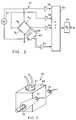
- the resistivity sensor 42 includes fixed resistors R1, R2 and R3 and a resistance cell 50 connected in a bridge configuration.
- a voltage source 52 is applied across the bridge and the values of the voltage at the nodes of the bridge are applied to a multiplexer 54 through buffer amplifiers 56, 58 and 60.
- a thermistor 62 is provided on the resistance cell 50 to measure the temperature of the ink passing through the cell 50.
- the outputs of the thermistor 62 is also applied to the multiplexer 54 through a buffer amplifier 64.
- Multiplexer 54 sequentially supplies the voltage values at the nodes of the bridge and the thermistor output value to the input of an analog to digital converter 66, which in turn digitizes the voltage values and supplies them sequentially to the logic and control unit 28 where the resistivity of the ink in resistance cell 50 is calculated from the known resistance R1, R2 and R3.
- the temperature of the ink can also be used to adjust the resistivity value calculated to normalize the resistivity value to a standard temperature.
- Fig. 3 is a perspective view of the resistance cell 50, which includes a hollow body 68 of insulating material.
- a first conductive metal fitting 70 is attached to one side of the hollow body 68 through which ink can enter the hollow body.
- a second similar conductive metal fitting is supplied on the opposite side of the hollow body 68.
- Conductive lugs 72 and 74 are in electrical contact with the conductive metal fittings and provide the connections to the bridge circuit shown in Fig. 2.
- fluid line 13 is connected to the conductive fitting 70 and its opposite counterpart.
- fluid line 32 is connected to the conductive fittings.
- Logic and control unit 28 monitors the state of the float switch 24. When the float switch 24 indicates that the level of ink in the main ink supply 14 is low (76), the logic and control unit checks whether the resistivity of the ink in the main ink supply 14 is lower (78) than a previously calculated desired value, thereby indicating that the concentration of colorant in the ink is high due to evaporation of carrier fluid. If the resistivity of the ink is low, the logic and control unit 28 opens valve 40 to allow replenishment carrier fluid to flow from supply 36 to the main ink supply 14 until the float switch 24 indicates that the main ink supply level is high (80).
- the logic and control unit 28 opens valve 34 to allow ink to flow from the supplemental ink supply 30 into the main ink supply 14 until the float switch in the main ink supply registers high (82). In this way, the resistivity of the ink and hence the concentration of the ink in the main ink supply is maintained at or near the desired value over time by refilling the main ink supply 14 from either the supplemental ink supply 30 or the replenishment carrier fluid supply 36 depending on the measured resistivity of ink in the main ink supply 14.
- the desired resistivity value of the ink in the main ink supply 14 is automatically updated when the resistivity of the ink in the supplemental ink supply 30 changes. This change may occur when a new batch of ink having a different resistivity is added to the supplemental ink supply 30.
- This automatic change is accomplished by the logic and control unit 28 monitoring the resistivity of the ink in the supplemental ink supply 30 via resistivity sensor 46.
- This new desired resistivity value is recalculated each time the main ink supply 14 is replenished from the supplemental ink supply 30. It has been observed for best results that the measurement of the resistivity of the ink should be done while the ink is flowing through the cell.
- the logic and control unit may calculate a proportion of supplemental ink and carrier fluid to add to the main ink supply to restore the resistivity to the desired value.
Landscapes
- Engineering & Computer Science (AREA)
- Quality & Reliability (AREA)
- Ink Jet (AREA)
- Extrusion Moulding Of Plastics Or The Like (AREA)
- Gasket Seals (AREA)
Claims (9)
- Dans une imprimante à jet d'encre continu utilisant de l'encre conductrice et ayant un réservoir d'encre principal, un réservoir d'encre supplémentaire et un réservoir de fluide porteur de remplissage, un système de remplissage d'encre comportant:a. un moyen pour détecter la résistivité de l'encre dans le réservoir d'encre principal; etb. un moyen qui réagit audit moyen de détection pour commander le transfert de l'encre et du fluide porteur respectivement du réservoir d'encre supplémentaire et du réservoir de fluide porteur au réservoir d'encre principal.
- Système de remplissage d'encre selon la revendication 1, dans lequel ledit moyen de commande comporte:a. un moyen pour détecter le moment où l'encre a diminué d'un volume prédéterminé dans ledit réservoir d'encre principal; etb. un moyen qui réagit audit moyen de détection de volume pour transférer ledit volume d'encre prédéterminé dudit réservoir d'encre supplémentaire audit réservoir d'encre principal quand la résistivité de l'encre dans ledit réservoir d'encre principal est supérieure à une valeur prédéterminée, et pour transférer ledit volume prédéterminé de fluide porteur dudit réservoir de fluide porteur de remplissage audit réservoir d'encre principal quand la résistivité de l'encre dans ledit réservoir d'encre principal est inférieure à ladite valeur prédéterminée.
- Système de remplissage d'encre selon la revendication 2, comportant en outre:a. un moyen supplémentaire de détection pour mesurer la résistivité de l'encre dans ledit réservoir d'encre supplémentaire; etb. un moyen qui réagit audit moyen supplémentaire de détection pour régler ladite valeur de résistivité prédéterminée.
- Système de remplissage d'encre selon la revendication 3, dans lequel ledit moyen de réglage règle ladite valeur de résistivité prédéterminée selon la règle suivante:

- Système de remplissage d'encre selon la revendication 2 ou la revendication 3, dans lequel ledit moyen de détection de volume comporte un commutateur flottant situé dans ledit réservoir d'encre principal.
- Système de remplissage d'encre selon la revendication 2 ou la revendication 3, dans lequel ledit moyen de détection de résistivité comporte:
un corps isolant creux, une paire de raccords en métal conducteur pour faire circuler l'encre dans le corps et une paire de connexions électriques auxdits raccords métalliques. - Procédé de remplissage d'encre dans une imprimante à jet d'encre du type ayant un réservoir d'encre principal, un réservoir d'encre supplémentaire et un réservoir de fluide porteur de remplissage, comportant les étapes de:a. détection de la résistivité de l'encre dans le réservoir d'encre principal; etb. remplissage du réservoir d'encre principal avec de l'encre provenant du réservoir d'encre supplémentaire et du fluide porteur provenant du réservoir de fluide porteur de remplissage, en fonction de la résistivité de l'encre dans le réservoir d'encre principal.
- Procédé selon la revendication 7, dans lequel ladite étape de remplissage comporte les étapes de:a. détection du moment où l'encre a diminué d'un volume prédéterminé dans le réservoir d'encre principal; etb. remplacement du volume prédéterminé d'encre dans le réservoir principal par de l'encre provenant du réservoir d'encre supplémentaire si la résistivité de l'encre dans le réservoir d'encre principal est supérieure à une valeur prédéterminée, et remplacement du volume prédéterminé d'encre dans le réservoir principal par du fluide porteur provenant du réservoir de fluide porteur de remplissage si la résistivité de l'encre dans le réservoir d'encre principal est inférieure à une valeur prédéterminée.
- Procédé selon la revendication 7 ou la revendication 8, comportant en outre les étapes de:a. détection de la résistivité de l'encre dans le réservoir d'encre supplémentaire; etb. mise à jour de ladite valeur prédéterminée en fonction de la résistivité de l'encre dans le réservoir d'encre supplémentaire.
Applications Claiming Priority (2)
| Application Number | Priority Date | Filing Date | Title |
|---|---|---|---|
| US97549592A | 1992-11-10 | 1992-11-10 | |
| US975495 | 1992-11-10 |
Publications (2)
| Publication Number | Publication Date |
|---|---|
| EP0597628A1 EP0597628A1 (fr) | 1994-05-18 |
| EP0597628B1 true EP0597628B1 (fr) | 1996-04-03 |
Family
ID=25523089
Family Applications (1)
| Application Number | Title | Priority Date | Filing Date |
|---|---|---|---|
| EP19930308818 Expired - Lifetime EP0597628B1 (fr) | 1992-11-10 | 1993-11-04 | Système de réapprovisionnement en encre dans une imprimante par jet d'encre continu |
Country Status (3)
| Country | Link |
|---|---|
| EP (1) | EP0597628B1 (fr) |
| DE (1) | DE69302076T2 (fr) |
| NO (1) | NO933799L (fr) |
Cited By (8)
| Publication number | Priority date | Publication date | Assignee | Title |
|---|---|---|---|---|
| US8070274B2 (en) | 2002-01-30 | 2011-12-06 | Hewlett-Packard Development Company, L.P. | Printing-fluid container |
| WO2013039941A1 (fr) | 2011-09-16 | 2013-03-21 | Eastman Kodak Company | Composition d'encre pour imprimante à jet d'encre en continu |
| WO2020086299A1 (fr) | 2018-10-26 | 2020-04-30 | Eastman Kodak Company | Encre aqueuse pour impression par jet d'encre et ensemble d'encres |
| WO2020086925A1 (fr) | 2018-10-26 | 2020-04-30 | The Procter & Gamble Company | Article absorbant sur lequel se trouvent des graphismes imprimés avec une encre sans conservateur et procédés de fabrication de celui-ci |
| WO2020086924A1 (fr) | 2018-10-26 | 2020-04-30 | The Procter & Gamble Company | Article absorbant avec motifs imprimés à l'aide d'une encre sans conservateur, et ses procédés de fabrication |
| WO2021041028A1 (fr) | 2019-08-27 | 2021-03-04 | Eastman Kodak Company | Procédé et ensemble d'encres pour impression jet d'encre |
| WO2022086704A1 (fr) | 2020-10-20 | 2022-04-28 | Eastman Kodak Company | Compositions aqueuses et revêtements opaques obtenus à partir de ces dernières |
| WO2024058928A1 (fr) | 2022-09-14 | 2024-03-21 | Eastman Kodak Company | Encres d'impression colorées aqueuses fluorescentes et procédés d'impression à jet d'encre |
Families Citing this family (26)
| Publication number | Priority date | Publication date | Assignee | Title |
|---|---|---|---|---|
| JP2842330B2 (ja) * | 1995-09-21 | 1999-01-06 | 日本電気株式会社 | 静電式インクジェット記録装置 |
| US7147310B2 (en) | 2002-01-30 | 2006-12-12 | Hewlett-Packard Development Company, L.P. | Printing-fluid container |
| US7452061B2 (en) | 2002-01-30 | 2008-11-18 | Hewlett-Packard Development Company, L.P. | Method and device for filling a printing-fluid container |
| US6962408B2 (en) | 2002-01-30 | 2005-11-08 | Hewlett-Packard Development Company, L.P. | Printing-fluid container |
| US7104630B2 (en) | 2003-07-31 | 2006-09-12 | Hewlett-Packard Development Company, L.P. | Printing-fluid container |
| US7004564B2 (en) | 2003-07-31 | 2006-02-28 | Hewlett-Packard Development Company, L.P. | Printing-fluid container |
| US6959985B2 (en) | 2003-07-31 | 2005-11-01 | Hewlett-Packard Development Company, L.P. | Printing-fluid container |
| US7188937B2 (en) | 2004-01-29 | 2007-03-13 | Hewlett-Packard Development Company, L.P. | Printing-fluid venting assembly |
| US8173215B2 (en) | 2009-05-29 | 2012-05-08 | Eastman Kodak Company | Continuous ink jet ink compositions |
| US8419176B2 (en) | 2009-05-29 | 2013-04-16 | Eastman Kodak Company | Aqueous compositions with improved silicon corrosion characteristics |
| US20110123714A1 (en) | 2009-11-24 | 2011-05-26 | Hwei-Ling Yau | Continuous inkjet printer aquous ink composition |
| US8398191B2 (en) | 2009-11-24 | 2013-03-19 | Eastman Kodak Company | Continuous inkjet printer aquous ink composition |
| US8434857B2 (en) | 2010-08-31 | 2013-05-07 | Eastman Kodak Company | Recirculating fluid printing system and method |
| US8430492B2 (en) | 2010-08-31 | 2013-04-30 | Eastman Kodak Company | Inkjet printing fluid |
| US8465578B2 (en) | 2011-03-31 | 2013-06-18 | Eastman Kodak Company | Inkjet printing ink set |
| WO2012149324A1 (fr) | 2011-04-29 | 2012-11-01 | Eastman Kodak Company | Remise en circulation d'un liquide pour l'impression par jet d'encre, système et procédé |
| US8764161B2 (en) | 2011-08-31 | 2014-07-01 | Eastman Kodak Company | Printing fluids including a humectant |
| US20140231674A1 (en) | 2013-02-18 | 2014-08-21 | Wayne Lee Cook | Ink jet printer composition and use |
| US9523011B2 (en) | 2014-06-23 | 2016-12-20 | Eastman Kodak Company | Recirculating inkjet printing fluid |
| WO2017091356A1 (fr) | 2015-11-24 | 2017-06-01 | Eastman Kodak Company | Fourniture d'une image opaque par injection d'encre |
| EP3380574B1 (fr) | 2015-11-24 | 2019-12-25 | Eastman Kodak Company | Dispersions de pigments et compositions d'encre pour jet d'encre |
| WO2017172380A1 (fr) | 2016-04-01 | 2017-10-05 | Eastman Kodak Company | Compositions d'encre pour jet d'encre et impression à jet d'encre aqueuse |
| US10138386B2 (en) | 2016-08-18 | 2018-11-27 | Eastman Kodak Company | Method of inkjet printing a colorless ink |
| US10189271B2 (en) | 2016-08-18 | 2019-01-29 | Eastman Kodak Company | Non-foaming aqueous particle-free inkjet ink compositions |
| JP7295940B2 (ja) | 2018-08-21 | 2023-06-21 | イーストマン コダック カンパニー | 水性前処理組成物及びそれから調製される物品 |
| US11433684B2 (en) | 2018-08-22 | 2022-09-06 | Hewlett-Packard Development Company, L.P. | Print apparatuses using reusable print agent containers |
Family Cites Families (4)
| Publication number | Priority date | Publication date | Assignee | Title |
|---|---|---|---|---|
| BE756224A (fr) * | 1969-09-23 | 1971-03-01 | Teletype Corp | Encre et appareil d'impression electrostatiques |
| US4121222A (en) * | 1977-09-06 | 1978-10-17 | A. B. Dick Company | Drop counter ink replenishing system |
| JPS5670962A (en) * | 1979-11-16 | 1981-06-13 | Ricoh Co Ltd | Controlling method for ink density |
| JPS59214656A (ja) * | 1983-05-19 | 1984-12-04 | Sanyo Electric Co Ltd | インクジエツトプリンタ |
-
1993
- 1993-10-22 NO NO933799A patent/NO933799L/no unknown
- 1993-11-04 EP EP19930308818 patent/EP0597628B1/fr not_active Expired - Lifetime
- 1993-11-04 DE DE1993602076 patent/DE69302076T2/de not_active Expired - Lifetime
Cited By (8)
| Publication number | Priority date | Publication date | Assignee | Title |
|---|---|---|---|---|
| US8070274B2 (en) | 2002-01-30 | 2011-12-06 | Hewlett-Packard Development Company, L.P. | Printing-fluid container |
| WO2013039941A1 (fr) | 2011-09-16 | 2013-03-21 | Eastman Kodak Company | Composition d'encre pour imprimante à jet d'encre en continu |
| WO2020086299A1 (fr) | 2018-10-26 | 2020-04-30 | Eastman Kodak Company | Encre aqueuse pour impression par jet d'encre et ensemble d'encres |
| WO2020086925A1 (fr) | 2018-10-26 | 2020-04-30 | The Procter & Gamble Company | Article absorbant sur lequel se trouvent des graphismes imprimés avec une encre sans conservateur et procédés de fabrication de celui-ci |
| WO2020086924A1 (fr) | 2018-10-26 | 2020-04-30 | The Procter & Gamble Company | Article absorbant avec motifs imprimés à l'aide d'une encre sans conservateur, et ses procédés de fabrication |
| WO2021041028A1 (fr) | 2019-08-27 | 2021-03-04 | Eastman Kodak Company | Procédé et ensemble d'encres pour impression jet d'encre |
| WO2022086704A1 (fr) | 2020-10-20 | 2022-04-28 | Eastman Kodak Company | Compositions aqueuses et revêtements opaques obtenus à partir de ces dernières |
| WO2024058928A1 (fr) | 2022-09-14 | 2024-03-21 | Eastman Kodak Company | Encres d'impression colorées aqueuses fluorescentes et procédés d'impression à jet d'encre |
Also Published As
| Publication number | Publication date |
|---|---|
| NO933799D0 (no) | 1993-10-22 |
| NO933799L (no) | 1994-04-27 |
| DE69302076T2 (de) | 1996-09-05 |
| EP0597628A1 (fr) | 1994-05-18 |
| DE69302076D1 (de) | 1996-05-09 |
Similar Documents
| Publication | Publication Date | Title |
|---|---|---|
| EP0597628B1 (fr) | Système de réapprovisionnement en encre dans une imprimante par jet d'encre continu | |
| US5526026A (en) | Concentration control for a continuous ink jet printer utilizing resistivity | |
| EP0585560B1 (fr) | Dispositif et procédé pour maintenir la concentration de l'encre dans un système | |
| KR950001101B1 (ko) | 잉크제트헤드, 잉크탱크, 잉크제트기록장치, 잉크잔류량 검출방법 및 잉크잔류량 검출장치 | |
| US7594717B2 (en) | Inkjet printer and method of controlling same | |
| US4125845A (en) | Ink jet print head pressure and temperature control circuits | |
| JP2933347B2 (ja) | インクジェット印刷ヘッド | |
| US6199969B1 (en) | Method and system for detecting nonfunctional elements in an ink jet printer | |
| EP0333325B1 (fr) | Dispositif d'ajustement des gouttes d'encre par compensation de la température | |
| JP3639330B2 (ja) | インク・ジェット・プリンタ | |
| US6561635B1 (en) | Ink delivery system and process for ink jet printing apparatus | |
| EP0042055B1 (fr) | Imprimantes à jet d'encre et procédé pour faire fonctionner des imprimantes à jet d'encre | |
| US7604312B2 (en) | Fluid ejection device with feedback circuit | |
| US4337468A (en) | Method and device for controlling concentration of ink for ink-jet printer | |
| US4677845A (en) | Device for detecting viscosity of liquid | |
| US5815175A (en) | Method and arrangement for monitoring the functioning of an ink print head | |
| JPH06222680A (ja) | 自己較正によるトナー濃度検出 | |
| US7325896B2 (en) | Temperature calibration for fluid ejection head | |
| JP6991864B2 (ja) | 液体吐出装置 | |
| JP7669156B2 (ja) | 画像記録装置 | |
| TW200422192A (en) | Methods and apparatus for reducing the print-job completion time for a printer having an intermittent-refill printhead | |
| US12552154B2 (en) | Liquid discharge apparatus and control method thereof | |
| ITTO970321A1 (it) | Dispositivo e metodo per controllare l'energia fornita ad un resistore di emissione di una testina di stampa termica a getto di inchiostro e | |
| JPH10805A (ja) | 静電式インクジェット記録装置 | |
| EP0500716A1 (fr) | Compensation des interferences entre les canaux d'une imprimante a jet d'encre. |
Legal Events
| Date | Code | Title | Description |
|---|---|---|---|
| PUAI | Public reference made under article 153(3) epc to a published international application that has entered the european phase |
Free format text: ORIGINAL CODE: 0009012 |
|
| AK | Designated contracting states |
Kind code of ref document: A1 Designated state(s): DE FR GB |
|
| 17P | Request for examination filed |
Effective date: 19940719 |
|
| 17Q | First examination report despatched |
Effective date: 19950711 |
|
| GRAA | (expected) grant |
Free format text: ORIGINAL CODE: 0009210 |
|
| AK | Designated contracting states |
Kind code of ref document: B1 Designated state(s): DE FR GB |
|
| REF | Corresponds to: |
Ref document number: 69302076 Country of ref document: DE Date of ref document: 19960509 |
|
| ET | Fr: translation filed | ||
| PLBE | No opposition filed within time limit |
Free format text: ORIGINAL CODE: 0009261 |
|
| 26N | No opposition filed | ||
| REG | Reference to a national code |
Ref country code: GB Ref legal event code: IF02 |
|
| REG | Reference to a national code |
Ref country code: GB Ref legal event code: 732E |
|
| REG | Reference to a national code |
Ref country code: FR Ref legal event code: TP |
|
| PGFP | Annual fee paid to national office [announced via postgrant information from national office to epo] |
Ref country code: FR Payment date: 20121113 Year of fee payment: 20 Ref country code: DE Payment date: 20121130 Year of fee payment: 20 |
|
| PGFP | Annual fee paid to national office [announced via postgrant information from national office to epo] |
Ref country code: GB Payment date: 20121025 Year of fee payment: 20 |
|
| REG | Reference to a national code |
Ref country code: DE Ref legal event code: R071 Ref document number: 69302076 Country of ref document: DE |
|
| REG | Reference to a national code |
Ref country code: GB Ref legal event code: PE20 Expiry date: 20131103 |
|
| PG25 | Lapsed in a contracting state [announced via postgrant information from national office to epo] |
Ref country code: GB Free format text: LAPSE BECAUSE OF EXPIRATION OF PROTECTION Effective date: 20131103 Ref country code: DE Free format text: LAPSE BECAUSE OF EXPIRATION OF PROTECTION Effective date: 20131105 |