EP0597717B1 - Einrichtung zur Messung eines Widerstandes einer elektrischen Hochspannungs-Widerstandsleitung - Google Patents
Einrichtung zur Messung eines Widerstandes einer elektrischen Hochspannungs-Widerstandsleitung Download PDFInfo
- Publication number
- EP0597717B1 EP0597717B1 EP19930309038 EP93309038A EP0597717B1 EP 0597717 B1 EP0597717 B1 EP 0597717B1 EP 19930309038 EP19930309038 EP 19930309038 EP 93309038 A EP93309038 A EP 93309038A EP 0597717 B1 EP0597717 B1 EP 0597717B1
- Authority
- EP
- European Patent Office
- Prior art keywords
- resistance
- cable
- conductor
- contact pieces
- measuring
- Prior art date
- Legal status (The legal status is an assumption and is not a legal conclusion. Google has not performed a legal analysis and makes no representation as to the accuracy of the status listed.)
- Expired - Lifetime
Links
Images
Classifications
-
- G—PHYSICS
- G01—MEASURING; TESTING
- G01R—MEASURING ELECTRIC VARIABLES; MEASURING MAGNETIC VARIABLES
- G01R15/00—Details of measuring arrangements of the types provided for in groups G01R17/00 - G01R29/00, G01R33/00 - G01R33/26 or G01R35/00
- G01R15/14—Adaptations providing voltage or current isolation, e.g. for high-voltage or high-current networks
Definitions
- This invention relates to an apparatus for measuring a resistance of a high tension resistance electrical cable to be used in an ignition cable or the like for an automobile or the like.
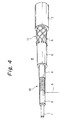
- FIG. 4 is a perspective view illustrating a prior high tension resistance electrical cable 8 a part of which is exposed. As shown in FIG.
- the high tension resistance electrical cable 8 comprises a strand like fiber 1 such as a glass fiber, polyamid fiber, etc., a coil core layer 2 which covers the strand like fiber with a synthetic resin such as a silicone resin or the like, a resistance wire 3 made of a metal wire such as a nickel-chromium resistance wire or the like which is spirally wound around the coil core layer 2 in its longitudinal direction, a conductive silicone rubber layer 4 which covers the resistance wire 3, an insulation layer 5 made of a synthetic rubber or the like which covers the layer 4, a net 6 made of a glass fiber which is provided on the outer face of the insulation layer 5, and a sheath layer 7 made of a silicone rubber or the like which covers the net 6 (see Japanese Patent Public Disclosure No. 60-3809 (1985)).
- a strand like fiber 1 such as a glass fiber, polyamid fiber, etc.
- a coil core layer 2 which covers the strand like fiber with a synthetic resin such as a silicone resin or the like
- a resistance wire 3 made of a
- a resistance conductor 10 is constituted of the strand like fiber 1, coil core layer 2, resistance wire and conductive silicone rubber layer 4 while a sheath outer layer 11 which covers the resistance conductor 10 is constituted of the insulation layer 5, net 6, and sheath layer 7.
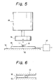
- FIG. 5 is a front side elevation view of a prior resistance-measuring apparatus and FIG. 6 is a partially enlarged view of the apparatus shown in FIG. 5, which shows another operating position.
- the resistance examination of the high tension resistance electrical cable 8 comprises the steps of: cutting the cable 8 fed successively from a stock drum or the like into a given length; stripping the sheath outer layer 11 from the cable 8 at the opposite ends; electrically connecting the exposed resistance conductor 10 to the resistance-measuring apparatus at the opposite ends; and measuring a resistance of the cable 8.
- the resistance-measuring apparatus as shown in FIG. 5, comprises a bed 14, a stationary copper plate 15 fixed on the bed 14 for contacting with the resistance conductor 10, a movable copper plate 16 attached to a raising and lowering means 18 above the stationary copper plate 15 for contacting with the resistance conductor 10, and a resistance meter 17 electrically connected to the stationary copper plates 15 (one of them is not shown in FIG. 5).
- the raising and lowering means 18 is an air cylinder or the like, which is supported on the bed and raises and lowers the movable copper plate 16 within a given range through a buffer mechanism not shown.
- the air cylinder 18 When exposed resistance conductor 10 is guided at a given position between the stationary copper plate 15 and the movable copper plate 16, the air cylinder 18 is actuated to lower the movable copper plate 16, the resistance conductor 10 is clamped between the plates 15 and 16. Then, the pair of stationary copper plates 15 are electrically connected to each other through the resistance conductor 10 and thus the resistance meter 17 measures the resistance of the resistance conductor 10.
- An object of the present invention is to provide a resistance-measuring apparatus for a high tension resistance electrical cable, which prevents a measured value of resistance from being dispersed.
- an apparatus for measuring a resistance of a high tension resistance electrical cable is provided as defined in claim 1.
- the elastic contact pieces contact with the resistance conductor in their resilient deformation when they clamp the resistance conductor at its opposite sides, a contact area therebetween becomes a curved plate, thereby settling their contact position and effectively preventing a measured value of resistance from being dispersed.
- the elastic contact pieces are elastically deformed when they are pressed to the resistance conductor at its opposite sides, the resistance conductor is prevented from being crushed.
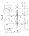
- FIG. 3 shows a schematic treating process of the coil type high tension resistance electrical cable 8 constructed by the same manner described above to be used in the automobile.
- the apparatus includes a cable cutting station 20 which cuts the high tension resistance electrical cable 8 fed successively from a stock drum not shown in a given length L, a stripping station 21 which stripes a sheath of the cable 8 at its opposite ends to expose the resistance conductor 10 by a given length S, and a resistance-measuring station 22 which measures a resistance of the cable 8.
- conveyors 24 such as endless chains or belts are intermittently driven and circulated.
- the conveyors 24 are provided with a plurality of clamps 25 spaced at a given distance in the longitudinal direction of the conveyor and actuated to open and close.
- the high tension resistance electrical cable 8 cut into the given length L at the cable cutting station 20 is clamped at opposite ends by the clamps 25 and fed in a feeding direction P of the conveyor 24 to the stripping station 21 and resistance measuring station 22.
- a stripping device not shown strips the sheath outer layer 11 of the cable 8 at its opposite ends to expose the resistance conductor 10 by the given length S.
- the cable 8 is fed to the resistance-measuring station 22 and the resistance of the cable 8 is measured by a resistance-measuring apparatus 26 arranged at the station 22.
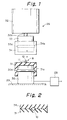
- the resistance-measuring apparatus 26 is provided with conductor-contacting mechanisms 27 disposed at a position where the stripped resistance conductor 10 of the cable 8 pass through, and a resistance meter 28 electrically connected to the conductor-contacting mechanisms 27.
- each conductor-contacting mechanism 27 includes a cylindrical conductive copper block 30 fixed on a bed 29, an elastic contact piece 31 mounted on an upper portion of the conductive copper block 30 for contacting with the conductor 10, a raising and lowering cylinder 32 such as an air cylinder secured to the bed 29 above the block 30, a cylindrical conductive copper block 33 secured to a distal end of a piston rod 32a which extends downwardly from the raising and lowering cylinder 32, and an elastic contact piece 34 mounted on a lower portion of the block 33.
- Each of the elastic contact pieces 31 and 34 is made of a conductive elastic material such as conductive silicone rubber or the like and formed into a cylinder shape with a bottom wall.
- the respective contact pieces 31 and 34 are closely mated with the respective copper blocks 30 and 33.
- the blocks 30 and 33 are provided on their outer faces with annular projections 30a and 33a while the elastic contact pieces 31 and 34 are provided on their interiors with annular grooves 31a and 34a associated with the annular projections 30a and 33a.
- the pieces 31 and 34 are coupled with the blocks 30 and 33 so that the projections 30a and 33a engage with the groves 31a and 34a, thereby preventing the pieces 31 and 34 from falling out of the blocks 30 and 33.
- the upper elastic contact piece 34 is moved down and up between an examination position where the upper piece 34 contacts with and presses the lower contact piece 31 and a stand-by position where the upper contact piece 34 is spaced away from the lower contact piece 31.
- the resistance meter 28 is electrically connected to each conductive copper block 30 of each conductor-contacting mechanism 27.
- the resistance-measuring apparatus 26 measures the resistance of the cable 8 by lowering the elastic contact piece 34 to the examination position by the cylinder 32 when the exposed resistance conductor 10 is fed to the given position between the elastic contact pieces 31 and 34, and by press-contacting the piece 31 with the piece 34 to clamp the conductor 10 therebetween. At this time, the resistance conductor 10 is press-contacted with the contact pieces 31 and 34, thereby electrically connecting the conductor 10 through the piece 31 to the copper block 30. Consequently, the resistance meter 28 can measure the resistance of the resistance conductor 10.
- the cylinder 32 After measuring the resistance, the cylinder 32 raises the elastic contact piece 34 to the stand-by position and the cable 8 is removed from the apparatus as faulty goods if the conductor 10 has not a given resistance.
- the elastic contact pieces 31 and 34 which are press-contacted with the resistance conductor 10 at its opposite sides are made of an elastic material, the pieces 31 and 34 are contacted with the conductor 10 in the elastic deformation when the upper contact piece 34 is lowered and contacted with the lower contact piece 31. Consequently, the contact area between the contact pieces 31, 34 and the resistance conductor 10 becomes a wide curved plane, thereby settling the contact position, minimizing the dispersion of resistance ( ⁇ 0.1K ⁇ ) and enhancing a reliability of goods. Further, the resistance conductor 10 is not crushed by the pieces 31 and 34 since the pieces are elastically deformed upon press-contacting.
- the elastic contact pieces clamp the resistance conductor in the elastic deformation at its opposite sides, thereby increasing the contact area, stabilizing the contact position, and minimizing a dispersion of the measured resistance value.
- the resistance conductor is not crushed by the contact pieces when they clamp the conductor, since the pieces are resiliently deformed.
Landscapes
- Physics & Mathematics (AREA)
- General Physics & Mathematics (AREA)
- Measurement Of Resistance Or Impedance (AREA)
- Testing Electric Properties And Detecting Electric Faults (AREA)
- Ignition Installations For Internal Combustion Engines (AREA)
Claims (1)
- Eine Einrichtung zum Messen des elektrischen Widerstands eines Hochspannungswiderstandskabels (8), wobei das Kabel (8) umfasst: einen Widerstandsleiter (10) einschließlich einer einzeldrahtähnlichen Faser (1), eine Spulenkernschicht (2), die eine äußere Umfangsoberfläche der einzeldrahtähnlichen Faser (1) bedeckt, und einen Widerstandsdraht (3), der spiralförmig um die Spulenkernschicht (2) gewickelt ist, und eine äußere Mantelschicht (7), die einen äußeren Umfangsabschnitt des Widerstandsleiters (10) bedeckt, wobei das Kabel auf eine gegebene Länge zugeschnitten wird und die äußere Mantelschicht (11) an den gegenüberliegenden Enden des Kabels abgezogen wird, um den Widerstandsleiter (10) freizulegen; wobei die Einrichtung ein Paar von leitenden Kontaktteilen (31, 34) umfasst, die in Kontakt mit dem Widerstandsleiter (10) an gegenüberliegenden Seiten desselben gebracht werden können, um den Widerstand des Kabels (8) zu messen;
dadurch gekennzeichnet, dass die leitenden Kontaktteile elastische Kontaktteile (31, 34) sind, die eine Zylinderform und eine Bodenwand aufweisen und aus einem leitenden, elastischen Material hergestellt sind;
wobei jedes der elastischen Kontaktteile (31, 34) eng an einem entsprechenden leitenden Kupferblock (30, 33) durch einen Passeingriff der ringförmigen Vorsprünge (30a, 31a) auf den Leiterkupferblöcken (30, 33) mit ringförmigen Nuten (31a, 34a), die auf der Innenseite der elastischen Kontaktteile (31, 34) vorgesehen sind, befestigt ist, um zu verhindern, dass die elastischen Kontaktteile aus den Blöcken herausfallen;
und wobei während des Gebrauchs die elastischen Kontaktteile den Widerstandsleiter (10) an den gegenüberliegenden Seiten desselben bei der Messung des Widerstandes des Kabels einklemmen und drücken, während die äußere Umfangsoberfläche des Widerstandsleiters (10) gedrückt ist.
Applications Claiming Priority (3)
| Application Number | Priority Date | Filing Date | Title |
|---|---|---|---|
| JP8467792U JP2591443Y2 (ja) | 1992-11-12 | 1992-11-12 | 高圧抵抗電線用抵抗測定装置 |
| JP8467792U | 1992-11-12 | ||
| JP84677/92U | 1992-11-12 |
Publications (3)
| Publication Number | Publication Date |
|---|---|
| EP0597717A2 EP0597717A2 (de) | 1994-05-18 |
| EP0597717A3 EP0597717A3 (de) | 1995-04-19 |
| EP0597717B1 true EP0597717B1 (de) | 2002-02-20 |
Family
ID=13837338
Family Applications (1)
| Application Number | Title | Priority Date | Filing Date |
|---|---|---|---|
| EP19930309038 Expired - Lifetime EP0597717B1 (de) | 1992-11-12 | 1993-11-11 | Einrichtung zur Messung eines Widerstandes einer elektrischen Hochspannungs-Widerstandsleitung |
Country Status (3)
| Country | Link |
|---|---|
| EP (1) | EP0597717B1 (de) |
| JP (1) | JP2591443Y2 (de) |
| DE (1) | DE69331595D1 (de) |
Families Citing this family (2)
| Publication number | Priority date | Publication date | Assignee | Title |
|---|---|---|---|---|
| CN105021894A (zh) * | 2015-08-12 | 2015-11-04 | 深圳晶华显示器材有限公司 | 一种用于测量导电胶条的夹具 |
| KR102471060B1 (ko) * | 2015-12-14 | 2022-11-24 | 엘지디스플레이 주식회사 | 배선 저항 측정 장치 |
Family Cites Families (6)
| Publication number | Priority date | Publication date | Assignee | Title |
|---|---|---|---|---|
| US4004843A (en) * | 1975-09-25 | 1977-01-25 | Westinghouse Electric Corporation | Probe pin |
| DD124846A1 (de) * | 1976-03-16 | 1977-03-16 | ||
| CH657706A5 (fr) * | 1984-06-18 | 1986-09-15 | Gerard Andre Lavanchy | Procede et dispositif pour la mesure de resistance d'un conducteur. |
| US4843313A (en) * | 1984-12-26 | 1989-06-27 | Hughes Aircraft Company | Integrated circuit package carrier and test device |
| DE3843877C1 (en) * | 1988-12-24 | 1990-02-15 | Kabelmetal Electro Gmbh, 3000 Hannover, De | Device for measuring the conductor resistances in insulated wires of electrical cables |
| JPH02232569A (ja) * | 1989-03-06 | 1990-09-14 | Sumitomo Electric Ind Ltd | 極細電線断線危険箇所の予知方法 |
-
1992
- 1992-11-12 JP JP8467792U patent/JP2591443Y2/ja not_active Expired - Fee Related
-
1993
- 1993-11-11 EP EP19930309038 patent/EP0597717B1/de not_active Expired - Lifetime
- 1993-11-11 DE DE69331595T patent/DE69331595D1/de not_active Expired - Lifetime
Also Published As
| Publication number | Publication date |
|---|---|
| DE69331595D1 (de) | 2002-03-28 |
| EP0597717A3 (de) | 1995-04-19 |
| JPH0643578U (ja) | 1994-06-10 |
| JP2591443Y2 (ja) | 1999-03-03 |
| EP0597717A2 (de) | 1994-05-18 |
Similar Documents
| Publication | Publication Date | Title |
|---|---|---|
| US4110880A (en) | Cable harness assembly and electrical testing machine | |
| CA1072650A (en) | Multiconductor electrical cable termination | |
| US5607320A (en) | Cable clamp apparatus | |
| CA2182664C (en) | Electrical cable connector and method of making | |
| US4005518A (en) | Apparatus for connecting conductors in flat cable to terminals in a connector | |
| US4072387A (en) | Multiple conductor connector unit and cable assembly | |
| CA1286741C (en) | Cutting/clamping sleeve contact | |
| US4051383A (en) | Electrical harnesses and connecting devices therefor | |
| EP1041682B1 (de) | Kabelstecker in welchem zwei Kontakte einen Drahtkern eines Kabels zwischen sich befestigen | |
| CA2008601A1 (en) | Molded electrical connector and method for manufacturing same | |
| IE901947L (en) | A cable connector block for a screened pair cable | |
| US4179964A (en) | Ribbon cable splitting device | |
| JP2520066B2 (ja) | 電力線ハ―ネスの製造装置及び製造方法 | |
| JPH0731221B2 (ja) | 試験プラグ及び試験装置 | |
| EP0597717A2 (de) | Einrichtung zur Messung eines Widerstandes einer elektrischen Hochspannungs-Widerstandsleitung | |
| CA2051505C (en) | High impedance electrical cable and method of forming same | |
| US4786261A (en) | Electrical connector assembly for a truck-trailer jumper cable | |
| IE53939B1 (en) | Terminal element | |
| US4701137A (en) | Electrical connector for coaxial cables | |
| US5363549A (en) | Cable laminating and terminating system | |
| JPS6232564B2 (de) | ||
| JPH0711549B2 (ja) | 圧着不良端子検出方法 | |
| EP0212801B1 (de) | Kabelbaumherstellung | |
| US3614294A (en) | Device for rapidly interconnecting two insulated electrical conductors | |
| GB2221355A (en) | Grounding screened cables |
Legal Events
| Date | Code | Title | Description |
|---|---|---|---|
| PUAI | Public reference made under article 153(3) epc to a published international application that has entered the european phase |
Free format text: ORIGINAL CODE: 0009012 |
|
| 17P | Request for examination filed |
Effective date: 19931201 |
|
| AK | Designated contracting states |
Kind code of ref document: A2 Designated state(s): DE FR GB |
|
| PUAL | Search report despatched |
Free format text: ORIGINAL CODE: 0009013 |
|
| AK | Designated contracting states |
Kind code of ref document: A3 Designated state(s): DE FR GB |
|
| 17Q | First examination report despatched |
Effective date: 19991123 |
|
| GRAG | Despatch of communication of intention to grant |
Free format text: ORIGINAL CODE: EPIDOS AGRA |
|
| GRAG | Despatch of communication of intention to grant |
Free format text: ORIGINAL CODE: EPIDOS AGRA |
|
| GRAH | Despatch of communication of intention to grant a patent |
Free format text: ORIGINAL CODE: EPIDOS IGRA |
|
| GRAH | Despatch of communication of intention to grant a patent |
Free format text: ORIGINAL CODE: EPIDOS IGRA |
|
| REG | Reference to a national code |
Ref country code: GB Ref legal event code: IF02 |
|
| GRAA | (expected) grant |
Free format text: ORIGINAL CODE: 0009210 |
|
| AK | Designated contracting states |
Kind code of ref document: B1 Designated state(s): DE FR GB |
|
| PG25 | Lapsed in a contracting state [announced via postgrant information from national office to epo] |
Ref country code: FR Free format text: LAPSE BECAUSE OF FAILURE TO SUBMIT A TRANSLATION OF THE DESCRIPTION OR TO PAY THE FEE WITHIN THE PRESCRIBED TIME-LIMIT Effective date: 20020220 |
|
| REF | Corresponds to: |
Ref document number: 69331595 Country of ref document: DE Date of ref document: 20020328 |
|
| PG25 | Lapsed in a contracting state [announced via postgrant information from national office to epo] |
Ref country code: DE Free format text: LAPSE BECAUSE OF FAILURE TO SUBMIT A TRANSLATION OF THE DESCRIPTION OR TO PAY THE FEE WITHIN THE PRESCRIBED TIME-LIMIT Effective date: 20020522 |
|
| PG25 | Lapsed in a contracting state [announced via postgrant information from national office to epo] |
Ref country code: GB Free format text: LAPSE BECAUSE OF NON-PAYMENT OF DUE FEES Effective date: 20021111 |
|
| EN | Fr: translation not filed | ||
| PLBE | No opposition filed within time limit |
Free format text: ORIGINAL CODE: 0009261 |
|
| 26N | No opposition filed |
Effective date: 20021121 |
|
| GBPC | Gb: european patent ceased through non-payment of renewal fee |