EP0597720B1 - Méthode de transmissionm TDM/TDMA - Google Patents
Méthode de transmissionm TDM/TDMA Download PDFInfo
- Publication number
- EP0597720B1 EP0597720B1 EP93309045A EP93309045A EP0597720B1 EP 0597720 B1 EP0597720 B1 EP 0597720B1 EP 93309045 A EP93309045 A EP 93309045A EP 93309045 A EP93309045 A EP 93309045A EP 0597720 B1 EP0597720 B1 EP 0597720B1
- Authority
- EP
- European Patent Office
- Prior art keywords
- sequence
- base station
- outstation
- correlator
- correlation
- Prior art date
- Legal status (The legal status is an assumption and is not a legal conclusion. Google has not performed a legal analysis and makes no representation as to the accuracy of the status listed.)
- Expired - Lifetime
Links
Images



Classifications
-
- H—ELECTRICITY
- H04—ELECTRIC COMMUNICATION TECHNIQUE
- H04J—MULTIPLEX COMMUNICATION
- H04J7/00—Multiplex systems in which the amplitudes or durations of the signals in individual channels are characteristic of those channels
-
- H—ELECTRICITY
- H04—ELECTRIC COMMUNICATION TECHNIQUE
- H04B—TRANSMISSION
- H04B10/00—Transmission systems employing electromagnetic waves other than radio-waves, e.g. infrared, visible or ultraviolet light, or employing corpuscular radiation, e.g. quantum communication
- H04B10/27—Arrangements for networking
- H04B10/272—Star-type networks or tree-type networks
-
- H—ELECTRICITY
- H04—ELECTRIC COMMUNICATION TECHNIQUE
- H04J—MULTIPLEX COMMUNICATION
- H04J3/00—Time-division multiplex systems
- H04J3/02—Details
- H04J3/06—Synchronising arrangements
- H04J3/0635—Clock or time synchronisation in a network
- H04J3/0682—Clock or time synchronisation in a network by delay compensation, e.g. by compensation of propagation delay or variations thereof, by ranging
-
- H—ELECTRICITY
- H04—ELECTRIC COMMUNICATION TECHNIQUE
- H04L—TRANSMISSION OF DIGITAL INFORMATION, e.g. TELEGRAPHIC COMMUNICATION
- H04L7/00—Arrangements for synchronising receiver with transmitter
- H04L7/04—Speed or phase control by synchronisation signals
- H04L7/041—Speed or phase control by synchronisation signals using special codes as synchronising signal
- H04L7/043—Pseudo-noise [PN] codes variable during transmission
Definitions
- This invention relates to a telecommunications method and in particular to a method employing the time division multiplex/time division multiple access (TDM/TDMA) principle.
- TDM/TDMA time division multiplex/time division multiple access
- the TDM/TDMA principle is well known in radio systems or passive optical networks (PONs), where it is employed to permit transmission between a single base station and a plurality of outstations.
- PONs passive optical networks
- the information (traffic) is broadcast to all outstations, but upstream it is transmitted in bursts, each of which must be timed to avoid mutual interference (overlap) so that at any time the base station only receives data from one outstation.
- a new outstation is to be connected its time of transmission must be such that it does not interfere with existing traffic transmissions and the processing required to ensure this is referred to as marshalling.
- EP-A-0190771 describes a method of initially establishing burst acquisition in a TDMA satellite communications system.
- a general review of synchronisation techniques in a TDMA satellite switched system is given by C R Carter in IEEE transactions on Communications, vol.28, no.8, August 1980, pages 1291-1302.
- a known method of marshalling involves reservation of a period of no transmission in the upstream frame (a window). It will be appreciated that the base station broadcasts information to all outstations employing a frame, which is typically of length 125 microseconds. The outstations are all able to receive the downstream traffic at a different time, depending on their distance from the base station and the propagation delay.
- the window in the upstream traffic flow must be at least as large as the uncertainty in the downstream and upstream loop delay.
- the loop delay may be 200 microseconds for a 20Km range (i.e.
- the outstations may be up to 20Km from the base station), requiring a 200 microsecond window, which would result in an equivalent additional delay in the upstream traffic, the need for all operating outstations to queue for one window's duration traffic and necessitates subsequent storage facilities, and a loss of bandwidth given by the product of the frequency of the window and its size in bits.
- TDMA time division multiple access
- the sequence and its phase can be detected by a correlation process.
- phase discrimination relative to frame boundaries use of an upstream traffic free window in which to operate a correlation/phase discriminator; a correlator design comprising an analogue to digital converter or a comparator to which noise dominated marshalling sequence signals received from an outstation are applied, a multiplier whereby the received signals are multiplied by a reference correlation sequence and a summer/up down counter to which the multiplier output is applied.
- the sequence can be generated at the outstation by means of reset scramblers or the retransmission of the received scrambler sequence as transmitted from the base station free running scrambler.
- the method has advantages over the prior art in that it provides the means to handle the attachment of several outstations while requiring only a small allocation of bandwidth and consequential delay.
- the marshalling of a new outstation is achieved by the transmission of a low level data sequence which is sent at a level which is below that which degrades the ability of the base station detector to correctly receive the traffic being received from outstations in the steady state.
- the signal to noise ratio required by a detector for a bit error ratio less than 10 -9 is approximately 11dB (optical), consequently, an outstation to be marshalled must transmit at a level such that the incident power of that marshalling signal at the base station receiver is at least 11dB lower than the weakest expected steady outstation.
- FIG 1 A timing diagram showing the transmission from the two outstations in respective transmission windows and an unused portion of the frame is given in figure 2.
- the lower line IV illustrates the base station received frame. This consists of a marshalling window of M bits, a sub frame received from outstation 1, a subframe received from outstation 2, and an unused portion of the frame.
- the delay from outstation 1 to the base station 4 results in the time at which the outstation subframe bursts SF 1 , is transmitted being as illustrated, likewise for outstation 2 and burst SF 2 .
- Subframe burst SF 3 from an additional outstation 3 which is to be marshalled must be transmitted so that it is received within the unused portion of the frame and must therefore be within the time envelope indicated on the third line of the timing diagram III, the purpose of the marshalling method being to determine the delay.
- the outstation 3 requiring to be marshalled will receive downstream data from the base station 4.
- This data will include a recognisable frame word, from which frame boundaries can be deduced.
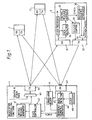
- the downstream frame format will be similar to the upstream format as illustrated in figure 2, line IV, except that the downstream marshalling window is not needed, and may be used instead to convey control messages to the outstations to control the marshalling process originated in the control message generator 41 as a result of the state controller 42 and being routed via the multiplexer 43 to the transmitter 44 for broadcasting to each outstation.
- Outstation 3 is therefore able to be controlled in its actions from the base station and has a time reference comprising the cyclically occurring frame boundary, which may be supplemented by a superframe identifier also transmitted downstream consisting, for example, of a 16 bit word incremented in each frame as a message.
- the sequence of events which is to occur is defined in Fig. 3.
- the base station does not know that an outstation is trying to attach, so it will send out an instruction for any prospective outstation to transmit its sequence.
- the transmitted sequence (S i ) should have the property that the auto-correlation product has a fixed and uniform value for all time shifts other than 0 (or equivalently the sequence length L).
- the receiver block RX49 may consist of an optical receiver converting incident optical power into electrical signals.
- the correlator may be realised using analogue correlation methods or digital methods, the latter will be described.
- the electrical signal from the RX front-end 49 may be directly converted as illustrated in Fig. 5 using an analogue to digital converted 51 and fed into the correlator, comprising the multiplier 52, reference correlation sequence source 53 and a summation circuit 54 comprising an adder and a memory (not shown).
- the correlator may be replicated L times so as to check all possible phases of the sequence over the same period employing different value of delay (k), or one correlator may be operated L times.
- the summation circuit 54 will be cumulatively incremented by the component of the signal received from the outstation that is in phase with the reference sequence whilst noise having a zero mean value will not be cumulative and hence over a sufficient number of samples, an originally dominant noise to signal ratio will result in the in phase component causing one of the L correlators to reach a predefined detection threshold.
- the ideal correlator behaviour is illustrated in Fig. 4, corresponding to the ideal correlator realisation of Fig. 5.
- the sequence is transmitted continuously.
- the sequence generator 38 at the outstation to be marshalled is synchronised to the same value (e.g. all 1s), at the same position in the same frame as the reference sequence generator, 46 at the base station. Consequently the outstation reference sequence generator start time (in absolute terms) is delayed compared to the base station reference due to the downstream propagation delay. Upstream, when received it has been further delayed by the upstream propagation delay. It is the purpose of the base station receiver 49 and correlator block 45 to determine this offset.
- the DC balance in the reference sequence applied to the b base station correlator(s) will reduce or eliminate the effects of DC offsets in the sampled signal.
- Fig. 6 This is a 1 bit correlation detector whose threshold behaviour is shown in Fig. 7.
- a 1 bit correlation detector behaves as the A/D based version but with "DC" offset due to noise dominating decisions.
- a comparator in place of the analogue to digital correlator, a comparator is used which may be the same comparator as used in the data detection block 47 of Fig. 1. Because the input noise dominated during the marshalling window, the comparator output will on average be 50% high and 50% low.
- the presence of the outstation marshalling sequence will alter the balance of ones and zeros producing a weak component of the marshalling sequence, since a noise value lying just below the one/zero threshold will be pushed over it by a weak marshalling sequence one.
- the output of the detector is binary (as illustrated) and consequently the correlation product will be binary and the summation circuit becomes an up/down counter.
- the noise variance of the correlation sum value is proportional to the number of correlated samples.
- the correlator may be replicated L times so that one of L threshold detectors detects the presence of the outstation transmitting the marshalling sequence.
- the value of the reference sequence delay (k) as applied to the particular correlator that reaches this threshold first will represent the sum of the downstream and upstream delay. This value may therefore be transmitted in a message to the outstation so that it can place its subframe correctly in the unused part of the upstream frame.
- the correlator consists of a sum of products circuit and the threshold detector may consist of a register defining the threshold, fed to one input of a comparator, the other input to which is the correlator output.
- an up-down counter may be substituted for the 'summer' which is incremented when the correlator product is a one, and decremented when the correlator product is a zero thus directly giving the deviation D.
- the time from which the instruction to the outstation was sent to synchronise and commence transmission of the marshalling sequence to the time at which the correlator reaches the predefined threshold, can be used as a measure of the incident power of that outstation. If this time is short, then this indicates the outstation signal path has low loss and the outstation may be instructed to transmit its subframes at a lower power level so as to reduce the dynamic range requirements of the base station receiver.
- sequence length in the system described needs to exceed the delay uncertainty, consequently a sequence length of several thousand bits will be required to identify uniquely the position.
- a typical value for the marshalling window is 50 octets with a clock frequency of 50 Mbit/s per second corresponding to a period of approximately 5 microseconds.
- Fig 8a shows the Gaussian amplitude distribution (zero mean and standard variation sigma). The probability at the mean is 0.399 (0.4 as above).
- 8b is a table indicating for correlation signal to noise ratio W(dB), and for a number of samples S, the deviation D from the mean expected number of ones and the standard deviation sigma giving the expected statistical variation.
- the column time assumes by way of example marshalling sampling window bandwidth of (1/0.28)mbit/s.
- the ratio of the deviation D to sigma is a measure of the reliability of the method, this ratio increasing with S.
- the basic correlation scheme illustrated in Fig. 5 includes a threshold detector.
- a frequent requirement of attachment mechanisms within telecommunications systems is minimisation of the elapsed time.
- the threshold detector referred to above compares the count value of the correlator against a fixed value. This value must be calculated so that if integration proceeds for the maximum period, then the probability that in the absence of a signal, the threshold will be exceeded due to random fluctuations in the correlator value alone will be constrained to a required minimum, C, typically 0.001. If the threshold is set in this way for the maximum integration period, then it will provide an un necessarily great degree of protection against spurious detection in the early stages of the correlation step.
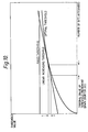
- a threshold detector which checked the correlator value for equivalence to the varying quantity T(n) would offer optimal performance in terms of both the speed with which the result might be obtained and the confidence in the result obtained, a threshold detector would typically be realised in digital hardware so as to approximate this function while effecting economies in design.
- One such approximation T1(n) would be a linear approximation as illustrated in Fig. 10 which is a graph of optimal, linear increasing and fixed thresholds against integration period.
- a circuit to realise such a linearly increasing threshold is illustrated in Fig. 11.
- the circuit comprises a number of counters which are standard binary up or down counters. When one of these counters reaches its terminal value (0 for a down counter, maximum value for an up counter) then it automatically reloads (O for a down counter, maximum value for an up counter).
- One such counter 61 the correlator select down counter, is a continuously running up counter which selects each correlator in turn and has a maximum value of the number of correlators employed.
- the threshold increment down counter 62 counts the number of bits or bytes correlated until the period between "threshold increments" is reached. When this occurs the threshold up counter 63 is incremented. The value of this is compared with the correlator count by a comparator 64.
- the block threshold detected logic 65 determines whether the correlator has reached a positive or negative threshold. The process is controlled by control logic 66.
Landscapes
- Engineering & Computer Science (AREA)
- Computer Networks & Wireless Communication (AREA)
- Signal Processing (AREA)
- Computing Systems (AREA)
- Physics & Mathematics (AREA)
- Electromagnetism (AREA)
- Synchronisation In Digital Transmission Systems (AREA)
- Time-Division Multiplex Systems (AREA)
Claims (8)
- Procédé de triage d'une station externe supplémentaire d'un système de télécommunications multiplexées par répartition dans le temps (TDMA), le système comprenant plusieurs stations externes (1, 2, 3) et une station de base (4) que les stations externes se partagent par répartition dans le temps, le procédé comprenant les étapes suivantes :caractérisé en ce que la détection de séquence et la discrimination de phase sont exécutées à la station de base par un processus de corrélation (45), et les instructions transmises par la station de base comprennent un mot de trame à partir duquel les limites de la trame et une référence de temps peuvent être déduites par la station externe supplémentaire.la transmission, par la station de base, d'instructions destinées à une station externe supplémentaire afin qu'elle transmette,la transmission, par la station externe supplémentaire, d'une séquence (38) à un niveau inférieur à la sensibilité au bruit d'un récepteur de la station de base, etla détection de la séquence et la discrimination de la phase de la séquence détectée, et, à l'aide de la phase obtenue par discrimination, la détermination du retard de boucle pour la station externe supplémentaire,
- Procédé selon la revendication 1, caractérisé en ce que le processus de corrélation comprend la comparaison de la séquence détectée à une séquence identique produite par un générateur (46) de la station de base dans un corrélateur (45), et en ce que, après la détermination du retard de boucle pour la station externe supplémentaire, le retard déterminé est transmis à la station externe de manière que la station externe puisse aligner sa transmission dans une fenêtre respective de transmission.
- Procédé selon la revendication 2, caractérisé en ce que le système est un réseau optique passif (PON), en ce que le récepteur de la station de base est un récepteur optique qui transforme l'énergie optique incidente en un signal électrique, et en ce que le signal électrique est directement transformé, dans un convertisseur analogique-numérique, avant l'application au corrélateur qui comporte un circuit multiplicateur et un compteur-décompteur-circuit de sommation suivi d'un détecteur à seuil.
- Procédé selon la revendication 3, caractérisé en ce que le même corrélateur est utilisé pour chaque position de la séquence, avec application de valeurs différentes du retard.
- Procédé selon la revendication 3, caractérisé en ce qu'un corrélateur respectif est utilisé pour chaque position de la séquence, chaque position ayant une valeur respective du retard.
- Procédé selon la revendication 3, caractérisé en ce que, à la station externe supplémentaire, la séquence est transmise de façon continue alors que, à la station de base, le processus de corrélation est réalisé au cours d'une fenêtre de triage.
- Procédé selon la revendication 3, caractérisé en ce que le seuil de détection augmente au cours du temps afin que le rapport de l'écart dû à la séquence de corrélation et de l'écart statistique dû au bruit soit normalisé approximativement et que le temps de détection de l'intensité d'un signal donné de corrélation soit réduit.
- Procédé selon l'une quelconque des revendications précédentes, dans lequel la séquence est une séquence pseudo-aléatoire de longueur maximale.
Applications Claiming Priority (4)
| Application Number | Priority Date | Filing Date | Title |
|---|---|---|---|
| GB9223740 | 1992-11-12 | ||
| GB929223740A GB9223740D0 (en) | 1992-11-12 | 1992-11-12 | Telecommunications systems |
| GB9312911A GB2272610B (en) | 1992-11-12 | 1993-06-22 | Telecommunications systems |
| GB9312911 | 1993-06-22 |
Publications (3)
| Publication Number | Publication Date |
|---|---|
| EP0597720A2 EP0597720A2 (fr) | 1994-05-18 |
| EP0597720A3 EP0597720A3 (fr) | 1994-10-19 |
| EP0597720B1 true EP0597720B1 (fr) | 1999-05-19 |
Family
ID=26301957
Family Applications (1)
| Application Number | Title | Priority Date | Filing Date |
|---|---|---|---|
| EP93309045A Expired - Lifetime EP0597720B1 (fr) | 1992-11-12 | 1993-11-11 | Méthode de transmissionm TDM/TDMA |
Country Status (4)
| Country | Link |
|---|---|
| US (1) | US5528596A (fr) |
| EP (1) | EP0597720B1 (fr) |
| DE (1) | DE69324998T2 (fr) |
| GB (1) | GB2272610B (fr) |
Families Citing this family (28)
| Publication number | Priority date | Publication date | Assignee | Title |
|---|---|---|---|---|
| EP0616444A3 (fr) * | 1993-03-15 | 1994-10-19 | Koninkl Philips Electronics Nv | Système de télécommunication avec détermination de distance. |
| JP4064450B2 (ja) * | 1994-03-29 | 2008-03-19 | ブリティッシュ・テレコミュニケーションズ・パブリック・リミテッド・カンパニー | 光通信ネットワーク |
| GB2290680B (en) * | 1994-06-22 | 1998-11-18 | Northern Telecom Ltd | Telecommunications system |
| DE4438344C1 (de) * | 1994-10-27 | 1996-08-01 | Nokia Telecommunications Oy | Abstimmungsverfahren für Punkt-zu-Multipunkt Kommunikationssysteme |
| JP3290831B2 (ja) * | 1994-11-21 | 2002-06-10 | 明星電気株式会社 | アンテナ装置及び基地局 |
| US5809093A (en) * | 1995-06-02 | 1998-09-15 | Dsc Communications Corporation | Apparatus and method of frame aligning information in a wireless telecommunications system |
| GB2301752B (en) * | 1995-06-02 | 2000-03-29 | Dsc Communications | Control message transmission in telecommunications systems |
| GB2302240B (en) * | 1995-06-02 | 2000-01-12 | Dsc Communications | Apparatus and method of frame aligning information in a wireless telecommunications system |
| GB2301717B (en) * | 1995-06-02 | 1999-08-11 | Dsc Communications | Network controller for monitoring the status of a network |
| GB2301751B (en) * | 1995-06-02 | 2000-02-09 | Dsc Communications | Control message transmission in telecommunications systems |
| US5696766A (en) * | 1995-06-02 | 1997-12-09 | Dsc Communications Corporation | Apparatus and method of synchronizing a transmitter in a subscriber terminal of a wireless telecommunications system |
| US5742595A (en) * | 1995-06-02 | 1998-04-21 | Dsc Communications Corporation | Processing CDMA signals |
| GB2301712B (en) * | 1995-06-02 | 2000-02-23 | Dsc Communications | Integrated directional antenna |
| US5745496A (en) * | 1995-06-02 | 1998-04-28 | Dsc Communications Corporation | Apparatus and method of establishing a downlink communication path in a wireless telecommunications system |
| GB2301735B (en) * | 1995-06-02 | 1999-07-28 | Dsc Communications | Message handling in a telecommunications network |
| US5915216A (en) * | 1995-06-02 | 1999-06-22 | Dsc Communications Corporation | Apparatus and method of transmitting and receiving information in a wireless telecommunications system |
| CA2224605C (fr) * | 1995-06-27 | 2002-10-22 | British Telecommunications Public Limited Company | Synchronisation dans des reseaux de communication numeriques |
| US5793772A (en) * | 1995-11-29 | 1998-08-11 | Motorola, Inc. | Method and apparatus for synchronizing timing of components of a telecommunication system |
| GB9602809D0 (en) * | 1996-02-12 | 1996-04-10 | Northern Telecom Ltd | A bidirectional communications network |
| US5867292A (en) * | 1996-03-22 | 1999-02-02 | Wireless Communications Products, Llc | Method and apparatus for cordless infrared communication |
| GB2312346B (en) * | 1996-04-20 | 2000-07-12 | Northern Telecom Ltd | Marshalling in optical tdma systems |
| DE19737135C1 (de) * | 1997-08-26 | 1999-04-15 | Siemens Ag | Verfahren zum Übermitteln von Einmeßinformationen an eine zentrale Einrichtung von angeschlossenen Komponenten in einem Punkt zu Multipunkt-Kommunikationssystem |
| DE19914793A1 (de) * | 1999-03-31 | 2000-10-26 | Siemens Ag | Verfahren und Anordnung zur Messung der Signalqualität in einem optischen Übertragungssystem |
| US6798791B1 (en) * | 1999-12-16 | 2004-09-28 | Agere Systems Inc | Cluster frame synchronization scheme for a satellite digital audio radio system |
| US20020063932A1 (en) * | 2000-05-30 | 2002-05-30 | Brian Unitt | Multiple access system for communications network |
| WO2004057900A1 (fr) * | 2002-12-20 | 2004-07-08 | Nokia Corporation | Procede et systeme d'attribution de canaux dans un reseau de communication cellulaire |
| US20050250466A1 (en) * | 2004-04-26 | 2005-11-10 | Hellosoft Inc. | Method and apparatus for improving MLSE in the presence of co-channel interferer for GSM/GPRS systems |
| FR2926937A1 (fr) * | 2008-01-24 | 2009-07-31 | Canon Kk | Procedes de synchronisation d'horloges applicatives dans un reseau de communication synchrone, dispositifs d'emission et de reception, produit programme d'ordinateur et moyen de stockage correspondants. |
Family Cites Families (11)
| Publication number | Priority date | Publication date | Assignee | Title |
|---|---|---|---|---|
| US3530252A (en) * | 1966-11-16 | 1970-09-22 | Communications Satellite Corp | Acquisition technique for time division multiple access satellite communication system |
| US3953674A (en) * | 1975-04-04 | 1976-04-27 | Nasa | Telemetry Synchronizer |
| US4168398A (en) * | 1976-11-10 | 1979-09-18 | Nippon Electric Co., Ltd. | Initial acquisition signal detection system for TDMA satellite communication |
| DE2653968A1 (de) * | 1976-11-27 | 1978-06-01 | Licentia Gmbh | Verfahren zum vergleich einer vorgegebenen zeichenfolge der laenge n mit einer seriell eintreffenden zeichenfolge |
| JPS6124338A (ja) * | 1984-07-12 | 1986-02-03 | Nec Corp | 多方向多重通信方式 |
| JPS61184014A (ja) * | 1985-02-08 | 1986-08-16 | Nec Corp | 時分割多元接続通信における初期接続方式及び装置 |
| GB8505516D0 (en) * | 1985-03-04 | 1985-04-03 | British Telecomm | Interface circuit |
| GB8727846D0 (en) * | 1987-11-27 | 1987-12-31 | British Telecomm | Optical communications network |
| GB8926548D0 (en) * | 1989-11-24 | 1990-01-17 | British Telecomm | Passive optical network |
| DE4108806C1 (fr) * | 1991-03-18 | 1992-01-30 | Litef Gmbh, 7800 Freiburg, De | |
| GB2272609B (en) * | 1992-11-12 | 1996-10-09 | Northern Telecom Ltd | Telecommunications systems |
-
1993
- 1993-06-22 GB GB9312911A patent/GB2272610B/en not_active Expired - Fee Related
- 1993-11-11 DE DE69324998T patent/DE69324998T2/de not_active Expired - Fee Related
- 1993-11-11 EP EP93309045A patent/EP0597720B1/fr not_active Expired - Lifetime
- 1993-11-12 US US08/152,278 patent/US5528596A/en not_active Expired - Fee Related
Also Published As
| Publication number | Publication date |
|---|---|
| DE69324998T2 (de) | 1999-09-30 |
| GB2272610A (en) | 1994-05-18 |
| DE69324998D1 (de) | 1999-06-24 |
| EP0597720A3 (fr) | 1994-10-19 |
| GB2272610B (en) | 1996-10-09 |
| GB9312911D0 (en) | 1993-08-04 |
| US5528596A (en) | 1996-06-18 |
| EP0597720A2 (fr) | 1994-05-18 |
Similar Documents
| Publication | Publication Date | Title |
|---|---|---|
| US5528596A (en) | Telecommunications systems | |
| US5651009A (en) | System and method for hybrid contention/polling protocol collision resolution using a depth first search technique | |
| US6731624B1 (en) | Sync signal detection method and radio communication system | |
| US5920551A (en) | Channel structure with burst pilot in reverse link | |
| US4506361A (en) | Retransmission control system | |
| JPH10510966A (ja) | Cdmaシステムのためのネットワーク参入チャンネル | |
| JP2001189764A (ja) | バースト・モード・プレアンブル | |
| CA2118848A1 (fr) | Systeme de telecommunication et station principale pour ce systeme | |
| WO1997020402A1 (fr) | Acquisition de signaux au moyen d'une transmission repetitive de sondes d'acces | |
| US5537241A (en) | Telecommunications system | |
| CA2272875A1 (fr) | Systeme de telecommunications a acces multiple par repartition dans le temps avec etalement du spectre | |
| EP0208475A2 (fr) | Réseau | |
| WO1993020633A1 (fr) | Procede et appareil permettant de modifier un syteme de recuperation de signal d'horloge fonctionnant par decision | |
| US5808766A (en) | Method for measuring a signal transmission delay time, central station, terminal station and network to perform this method | |
| US20070025316A1 (en) | Inter-station transmission method, radio base station monitoring method, and device using the method | |
| US5539783A (en) | Non-coherent synchronization signal detector | |
| EP0597721B1 (fr) | Méthode de transmission TDM/TDMA | |
| EA005608B1 (ru) | Способ синхронизации связи между множеством пользовательских терминалов и головным узлом в восходящем канале с использованием очу-модуляции | |
| WO2005093977A1 (fr) | Procede de signalisation d'informations de voie de retour a retard voix/donnees minimal | |
| Fralick et al. | Technological considerations for packet radio networks | |
| US6714557B1 (en) | Packet concatenation for increased transmission capacity | |
| US6967945B2 (en) | Method and system of communications using a pulse transmission protocol | |
| EP0766895B1 (fr) | Detection d'une sequence de mise en ordre de faible niveau | |
| US7057525B2 (en) | One way automatic meter reading system | |
| US20130100868A1 (en) | Phase coherent radio |
Legal Events
| Date | Code | Title | Description |
|---|---|---|---|
| PUAI | Public reference made under article 153(3) epc to a published international application that has entered the european phase |
Free format text: ORIGINAL CODE: 0009012 |
|
| AK | Designated contracting states |
Kind code of ref document: A2 Designated state(s): DE FR SE |
|
| PUAL | Search report despatched |
Free format text: ORIGINAL CODE: 0009013 |
|
| AK | Designated contracting states |
Kind code of ref document: A3 Designated state(s): DE FR SE |
|
| RHK1 | Main classification (correction) |
Ipc: H04J 3/06 |
|
| 17P | Request for examination filed |
Effective date: 19941025 |
|
| 17Q | First examination report despatched |
Effective date: 19970609 |
|
| GRAG | Despatch of communication of intention to grant |
Free format text: ORIGINAL CODE: EPIDOS AGRA |
|
| GRAG | Despatch of communication of intention to grant |
Free format text: ORIGINAL CODE: EPIDOS AGRA |
|
| GRAH | Despatch of communication of intention to grant a patent |
Free format text: ORIGINAL CODE: EPIDOS IGRA |
|
| GRAH | Despatch of communication of intention to grant a patent |
Free format text: ORIGINAL CODE: EPIDOS IGRA |
|
| GRAA | (expected) grant |
Free format text: ORIGINAL CODE: 0009210 |
|
| AK | Designated contracting states |
Kind code of ref document: B1 Designated state(s): DE FR SE |
|
| ET | Fr: translation filed | ||
| REF | Corresponds to: |
Ref document number: 69324998 Country of ref document: DE Date of ref document: 19990624 |
|
| RAP4 | Party data changed (patent owner data changed or rights of a patent transferred) |
Owner name: NORTEL NETWORKS CORPORATION |
|
| PLBE | No opposition filed within time limit |
Free format text: ORIGINAL CODE: 0009261 |
|
| 26N | No opposition filed | ||
| REG | Reference to a national code |
Ref country code: FR Ref legal event code: CD |
|
| PGFP | Annual fee paid to national office [announced via postgrant information from national office to epo] |
Ref country code: SE Payment date: 20041105 Year of fee payment: 12 |
|
| PG25 | Lapsed in a contracting state [announced via postgrant information from national office to epo] |
Ref country code: SE Free format text: LAPSE BECAUSE OF NON-PAYMENT OF DUE FEES Effective date: 20051112 |
|
| EUG | Se: european patent has lapsed | ||
| PGFP | Annual fee paid to national office [announced via postgrant information from national office to epo] |
Ref country code: FR Payment date: 20061103 Year of fee payment: 14 |
|
| PGFP | Annual fee paid to national office [announced via postgrant information from national office to epo] |
Ref country code: DE Payment date: 20061130 Year of fee payment: 14 |
|
| PG25 | Lapsed in a contracting state [announced via postgrant information from national office to epo] |
Ref country code: DE Free format text: LAPSE BECAUSE OF NON-PAYMENT OF DUE FEES Effective date: 20080603 |
|
| REG | Reference to a national code |
Ref country code: FR Ref legal event code: ST Effective date: 20080930 |
|
| PG25 | Lapsed in a contracting state [announced via postgrant information from national office to epo] |
Ref country code: FR Free format text: LAPSE BECAUSE OF NON-PAYMENT OF DUE FEES Effective date: 20071130 |