EP0597725B1 - System zum Abtasten von Körpern - Google Patents
System zum Abtasten von Körpern Download PDFInfo
- Publication number
- EP0597725B1 EP0597725B1 EP93309062A EP93309062A EP0597725B1 EP 0597725 B1 EP0597725 B1 EP 0597725B1 EP 93309062 A EP93309062 A EP 93309062A EP 93309062 A EP93309062 A EP 93309062A EP 0597725 B1 EP0597725 B1 EP 0597725B1
- Authority
- EP
- European Patent Office
- Prior art keywords
- image
- optical image
- radiation
- scanning
- ray source
- Prior art date
- Legal status (The legal status is an assumption and is not a legal conclusion. Google has not performed a legal analysis and makes no representation as to the accuracy of the status listed.)
- Expired - Lifetime
Links
Images

Classifications
-
- G—PHYSICS
- G01—MEASURING; TESTING
- G01V—GEOPHYSICS; GRAVITATIONAL MEASUREMENTS; DETECTING MASSES OR OBJECTS; TAGS
- G01V5/00—Prospecting or detecting by the use of ionising radiation, e.g. of natural or induced radioactivity
- G01V5/20—Detecting prohibited goods, e.g. weapons, explosives, hazardous substances, contraband or smuggled objects
- G01V5/22—Active interrogation, i.e. by irradiating objects or goods using external radiation sources, e.g. using gamma rays or cosmic rays
-
- G—PHYSICS
- G06—COMPUTING OR CALCULATING; COUNTING
- G06F—ELECTRIC DIGITAL DATA PROCESSING
- G06F17/00—Digital computing or data processing equipment or methods, specially adapted for specific functions
-
- A—HUMAN NECESSITIES
- A61—MEDICAL OR VETERINARY SCIENCE; HYGIENE
- A61B—DIAGNOSIS; SURGERY; IDENTIFICATION
- A61B6/00—Apparatus or devices for radiation diagnosis; Apparatus or devices for radiation diagnosis combined with radiation therapy equipment
- A61B6/12—Arrangements for detecting or locating foreign bodies
-
- G—PHYSICS
- G01—MEASURING; TESTING
- G01N—INVESTIGATING OR ANALYSING MATERIALS BY DETERMINING THEIR CHEMICAL OR PHYSICAL PROPERTIES
- G01N23/00—Investigating or analysing materials by the use of wave or particle radiation, e.g. X-rays or neutrons, not covered by groups G01N3/00 – G01N17/00, G01N21/00 or G01N22/00
- G01N23/02—Investigating or analysing materials by the use of wave or particle radiation, e.g. X-rays or neutrons, not covered by groups G01N3/00 – G01N17/00, G01N21/00 or G01N22/00 by transmitting the radiation through the material
- G01N23/04—Investigating or analysing materials by the use of wave or particle radiation, e.g. X-rays or neutrons, not covered by groups G01N3/00 – G01N17/00, G01N21/00 or G01N22/00 by transmitting the radiation through the material and forming images of the material
- G01N23/043—Investigating or analysing materials by the use of wave or particle radiation, e.g. X-rays or neutrons, not covered by groups G01N3/00 – G01N17/00, G01N21/00 or G01N22/00 by transmitting the radiation through the material and forming images of the material using fluoroscopic examination, with visual observation or video transmission of fluoroscopic images
-
- A—HUMAN NECESSITIES
- A61—MEDICAL OR VETERINARY SCIENCE; HYGIENE
- A61B—DIAGNOSIS; SURGERY; IDENTIFICATION
- A61B6/00—Apparatus or devices for radiation diagnosis; Apparatus or devices for radiation diagnosis combined with radiation therapy equipment
- A61B6/42—Arrangements for detecting radiation specially adapted for radiation diagnosis
- A61B6/4208—Arrangements for detecting radiation specially adapted for radiation diagnosis characterised by using a particular type of detector
- A61B6/4225—Arrangements for detecting radiation specially adapted for radiation diagnosis characterised by using a particular type of detector using image intensifiers
-
- G—PHYSICS
- G01—MEASURING; TESTING
- G01N—INVESTIGATING OR ANALYSING MATERIALS BY DETERMINING THEIR CHEMICAL OR PHYSICAL PROPERTIES
- G01N2223/00—Investigating materials by wave or particle radiation
- G01N2223/40—Imaging
- G01N2223/413—Imaging sensor array [CCD]
-
- G—PHYSICS
- G01—MEASURING; TESTING
- G01N—INVESTIGATING OR ANALYSING MATERIALS BY DETERMINING THEIR CHEMICAL OR PHYSICAL PROPERTIES
- G01N2223/00—Investigating materials by wave or particle radiation
- G01N2223/40—Imaging
- G01N2223/42—Imaging image digitised, -enhanced in an image processor
Definitions
- THIS invention relates to a system for scanning bodies.
- the invention may be used to scan human bodies to detect the presence thereon or therein of certain articles or substances.
- US-A-4 599 740 describes an X ray imaging system in which the scanning beam is collimated by a collimator comprising flat parallel vertical sides.
- the invention seeks to improve image quality in an X-ray imaging system for scanning objects.
- a method of scanning a body comprising the steps of producing a collimated beam of X-radiation, scanning the body with the collimated beam of X-radiation, converting X-radiation transmitted by the body into an optical image, intensifying the optical image, converting the optical image into an electronic image and manipulating the electronic image to produce a scanned image of the body or a portion thereof, characterised in that the beam of collimated X-radiation is produced by transmitting a beam of X-radiation from an X-ray source through a collimator which includes a stack of parallel plates, and furthermore in that the body is scanned by the collimated beam of X-radiation by causing relative linear movement to take place between the body and the X-ray source in a direction transverse to the plates of the collimator.
- the intensified optical image is preferably converted to a digital electronic image using CCD array detectors operated in drift scanning mode.
- the scanned image which is produced by manipulation of the digital electronic image is preferably a visual image of the body or portion thereof.
- the transmitted X-radiation is converted to an optical image by scintillator means. It is also preferred that intensification of the optical image is by means of an optical image intensifier and possibly also by one or more fibre-optic tapers used to convey the optical image.
- a series of first fibre-optic tapers conveys an optical image from a corresponding series of scintillators to an optical image intensifier which intensifies the optical image
- a series of second fibre-optic tapers conveys the intensified optical image to a corresponding series of CCD array detectors, operated in drift scanning mode, for conversion to an electronic image
- an X-ray source and imaging apparatus are located in opposition to one another on opposite sides of a scanning station and are supported by a carrier which is caused to move relative to a body located at the scanning station, thereby to scan the body.
- a carrier which is caused to move relative to a body located at the scanning station, thereby to scan the body.
- the body may be caused to move, possibly on a conveyor belt or other transportation system, relative to a stationary X-ray source and opposing imaging apparatus.
- apparatus for scanning a body comprising an X-ray source having a collimator, for scanning the body with a collimated beam of X-radiation, and imaging apparatus which includes means for converting X-radiation transmitted by the body into an optical image, the imaging apparatus including means for intensifying the optical image, means for converting the intensified optical image into an electronic image and means for manipulating the electronic image to produce a scanned image of the body or a portion thereof, characterised in that the collimator comprises a stack of spaced apart, parallel plates for collimating X-radiation produced by the X-ray source, thereby to provide the collimated beam of X-radiation, and means are provided for causing relative linear movement to take place between the body and the X-ray source in a direction transverse to the plates of the collimator.
- the intensity of the X-radiation is preferably such that the dose of X-radiation absorbed by the body during the scanning procedure is below physiologically unacceptable levels.
- the beam of X-radiation may be one which is of sufficiently low intensity for the human body to absorb an equivalent dose of 10 x 10 -6 sievert or less.
- the system described hereunder is specifically designed to scan a human body to detect the presence thereon or therein of one or more specific articles.
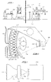
- the system as depicted in Figure 1 includes a scanning station designated with the numeral 10. Each person 12 who is to be scanned is brought to this station where, as illustrated, he stands upright during the scanning procedure. Alongside the scanning station 10 is an upright post 14 which supports a carrier 16.
- a suitable vertical drive unit (not illustrated) is provided on the post 14 or on the carrier 16 to move the carrier vertically up or down the post at a predetermined, constant linear speed.
- the carrier 14 incorporates an X-ray tube 18 which produces a generally horizontal, laterally fanned beam 20 of X-radiation and which directs the beam 20 through the scanning station 10 towards an arcuate detector and imaging unit 22 on the opposite side of the scanning station.
- the person 12 stands in the path of the beam 20.
- the carrier is moved vertically, either up or down, so that the beam 20 traverses the full height, or a selected portion only, of the person's body.
- the beam of X-radiation produced by the X-ray tube 18 is initially collimated in the vertical sense by a collimator 24 which limits the fanning of the beam 20 in a vertical plane.
- the beam 20 Having traversed the scanning zone, the beam 20 impinges on a series of laterally adjacent scintillator screens 26 which define, as illustrated, an arcuate scintillator screen array 28.
- the screens As photons of X-ray energy impinge on the scintillator screens 26, the screens generate photons of light energy, in the form of an optical image, with considerable gain, i.e. many light photons are generated for each impinging X-ray photon.
- the preferred X-ray tube 18 is a known line focus X-ray tube.
- X-rays are emitted from a source having the shape of a straight line, indicated in this case by the numeral 60.
- the line source 60 is orientated vertically as will be apparent from Figures 4 and 5, and has an emitting length corresponding to the desired height of the fanned X-ray beam 20.
- the divergent X-ray beam transmitted through the window 62 of the tube 18 is projected into a collimator 24 consisting of an outer housing 64 accommodating a stack 66 of closely spaced, thin, heavy metal plates 68.
- a collimator of this type is characterised by its grid ratio, which the ratio of the plate length in the direction of beam propagation to the clear spacing between the adjacent plates 68 in the stack. X-rays with a divergence exceeding the grid ratio impinge on the horizontal plate surfaces and are absorbed.
- the shape of the collimator is such that lateral fanning of the beam can take place.
- the X-ray beam 20 which finally emerge from the downstream end of the collimator 24 is a laterally fanned beam with a very low vertical divergence, determined in each case by the particular grid ratio of the collimator plate stack 66.
- the intensity of the optical image which is produced is proportional to the intensity of the impinging X-radiation.
- Fibre-optic tapers are known to achieve good optical collection of light while maintaining good spatial resolution and low distortion of the light.
- the fibre-optic taper 30 directs the optical image via a suitable coupling 32 to the input window of an image intensifier 34. It will be appreciated that the optical image presented to the input window of the image intensifier is de-magnified as a result of the shape of the fibre-optic taper. For each photon of light input to the image intensifier, the image intensifier outputs a number of light photons, via a further coupling 36, to a second fibre-optic taper 38. In other words, the image intensifier 34 intensifies the optical image presented to it by the fibre-optic taper 30.
- the second fibre-optic taper 38 directs the intensified optical image, again with de-magnification, to the front face of a CCD (charge-coupled device) array detector 40 which is coupled to an electronic interface module 42.
- CCD charge-coupled device
- Figure 3 of the drawings diagrammatically illustrates a single detector channel as described above.
- the CCD array detectors are driven in so-called drift scanning mode. Drift scanning moves the electronic image generated at the back of the CCD array detector and continuously enhances, or updates, this image from information gathered from the optical image that "moves" concurrently across the front face of the CCD detector as the carrier 16 moves.
- each point in the optical image must "move" in a straight line at a constant velocity i.e. the velocity at which the carrier 16 moves.
- the modules 42 interface, through a databus 46 and line 48, with a processing unit 50.
- each line of the electronic image is read out and enhanced by suitable digital electronic image processing enhancement apparatus.
- the unit 50 generates a video image on a monitor 52 which is viewed by an operator 54.
- an important consideration in any personal X-ray scanning technique is to ensure that X-ray dose absorbed by the body does not exceed physiologically harmful levels. This is particularly so in the case of a detection system in which frequent scanning of the body is necessary. For instance, where the system is used to detect the presence of goods which may have been stolen from the workplace, scanning may take place on a daily basis, each time a person leaves the workplace.
- the human body scanning system described above can be used to scan the bodies of persons with a view to detecting the presence thereon or therein of specific articles prone to theft.
- the bodies of persons may be scanned to detect concealed diamonds.
- any diamond particles in or on the person's body will absorb a greater proportion of the incident X-radiation than the surrounding body tissue or bone.
- the diamonds will cause relative attenuation of the X-ray signal and this will be visibly discernible in the final video image which is produced at the monitor 52.
- the X-ray tube voltage may be selected to be in the range 150KV to 160KV.
- the detection of diamonds on the human body is but one application of the invention.
- the human body could be scanned for the presence of other foreign objects, for instance pieces of metal, or for the presence of broken bones or other physiological irregularities, in a medical examination procedure.
- the X-ray tube voltage will be chosen to suit the particular application.
- the X-ray tube voltage could, for instance, be as low as 80KV.
- voltages as high as 600KV could be-employed.
- the human body could also be scanned for the presence of drugs or other prohibited substances or articles such as weapons at airport security checkpoints.
- the body itself is not necessarily a human body.
- the method and apparatus described above could be used to examine articles of luggage at airport security checkpoints.
- the contrast presented on the visual image may be set at an optimum level for accurate detection of a particular article or substance by appropriate initial setting of the operating voltage and current of the X-ray tube.
- video or electronic images produced by the apparatus described above can, if desired, be stored in memory by the processing unit 50.
Landscapes
- Health & Medical Sciences (AREA)
- Life Sciences & Earth Sciences (AREA)
- Physics & Mathematics (AREA)
- Engineering & Computer Science (AREA)
- General Physics & Mathematics (AREA)
- General Health & Medical Sciences (AREA)
- High Energy & Nuclear Physics (AREA)
- Medical Informatics (AREA)
- Nuclear Medicine, Radiotherapy & Molecular Imaging (AREA)
- Pathology (AREA)
- Radiology & Medical Imaging (AREA)
- Chemical & Material Sciences (AREA)
- Optics & Photonics (AREA)
- Molecular Biology (AREA)
- Surgery (AREA)
- Animal Behavior & Ethology (AREA)
- Biomedical Technology (AREA)
- Public Health (AREA)
- Veterinary Medicine (AREA)
- Multimedia (AREA)
- Theoretical Computer Science (AREA)
- Analytical Chemistry (AREA)
- Biochemistry (AREA)
- Biophysics (AREA)
- Immunology (AREA)
- Geophysics (AREA)
- Heart & Thoracic Surgery (AREA)
- General Life Sciences & Earth Sciences (AREA)
- Databases & Information Systems (AREA)
- Software Systems (AREA)
- Mathematical Physics (AREA)
- Data Mining & Analysis (AREA)
- General Engineering & Computer Science (AREA)
- Analysing Materials By The Use Of Radiation (AREA)
- Apparatus For Radiation Diagnosis (AREA)
- Vehicle Body Suspensions (AREA)
- Measuring And Recording Apparatus For Diagnosis (AREA)
- Measurement Of Radiation (AREA)
- Radiography Using Non-Light Waves (AREA)
- Measuring Arrangements Characterized By The Use Of Fluids (AREA)
Claims (21)
- Verfahren zum Abtasten eines Körpers, wobei das Verfahren die Schritte des Erzeugens eines kollimierten Röntgenstrahls, des Abtastens des Körpers mit dem kollimierten Röntgenstrahl, des Umsetzens der von dem Körper abgestrahlten Röntgenstrahlung in ein optisches Bild, des Verstärkens des optischen Bildes, des Umsetzens des optischen Bildes in ein elektronisches Bild und des Bearbeitens des elektronischen Bildes zum Erzeugen eines Abtastbildes des Körpers oder eines Teils desselben umfaßt, dadurch gekennzeichnet, daß der kollimierte Röntgenstrahl (20) durch Abstrahlen eines Röntgenstrahls von einer Röntgenstrahlungsquelle (18) durch einen Kollimator (24), der einen Stapel paralleler Platten (68) aufweist, erzeugt wird, und ferner dadurch gekennzeichnet, daß der Körper (12) mit dem kollimierten Röntgenstrahl abgetastet wird, indem eine relative Linearbewegung zwischen dem Körper und der Röntgenstrahlquelle in einer quer zu den Platten des Kollimators verlaufenden Richtung bewirkt wird.
- Verfahren nach Anspruch 1, dadurch gekennzeichnet, daß das verstärkte optische Bild in ein digitales elektronisches Bild unter Verwendung von im Drift-Abtastmodus betriebenen CCD-Array-Detektoren (40) umgesetzt wird.
- Verfahren nach Anspruch 1 oder 2, dadurch gekennzeichnet, daß das digitale elektronische Bild zur Erzeugung eines visuellen Bildes des Körpers oder eines Teils desselben bearbeitet wird.
- Verfahren nach einem der vorhergehenden Ansprüche, dadurch gekennzeichnet, daß die abgestrahlte Röntgenstrahlung durch Szintillatoreinrichtungen (26) in ein optisches Bild umgesetzt wird.
- Verfahren nach Anspruch 4, dadurch gekennzeichnet, daß das optische Bild durch einen Verstärker (34) für optische Bilder in Kombination mit einem oder mehreren zur Übertragung des optischen Bildes verwendeten faseroptischen Kegeln (30, 38) verstärkt wird.
- Verfahren nach Anspruch 5, dadurch gekennzeichnet, daß eine erste Reihe faseroptischer Kegel (30) zur Übertragung eines optischen Bildes von den Szintillatoreinrichtungen (26) zu einem Verstärker (34) für optische Bilder, der das Bild verstärkt, verwendet wird, und eine zweite Reihe von faseroptischen Kegeln (38) das verstärkte optische Bild an eine entsprechende Reihe von CCD-Array-Detektoren (40), die im Drift-Abtastmodus betrieben werden, zur Umsetzung in ein elektronisches Bild überträgt, wobei die erste und die zweite Reihe faseroptischer Kegel (30 und 38) zur Verkleinerung des von ihnen übertragenen Bildes dienen.
- Verfahren nach einem der vorhergehenden Ansprüche, dadurch gekennzeichnet, daß eine Röntgenstrahlungsquelle (18) und eine Abbildungsvorrichtung (22) einander entgegengesetzt auf gegenüberliegenden Seiten einer Abtaststation (10) angeordnet sind, die Röntgenstrahlungsquelle (18) und die Abbildungsvorrichtung (22) von einem Träger (14) gestützt werden, der relativ zu einem stationären Körper (12) bewegt wird, und die Röntgenstrahlungsquelle (18) einen aufgefächerten Röntgenstrahl (20) ausgibt, der in der Richtung der Relativbewegung des Trägers (14) kollimiert wird.
- Verfahren nach Anspruch 7, dadurch gekennzeichnet, daß der Körper ein menschlicher Körper (12) ist und der Träger (14) vertikal in bezug zu einem an der Abtaststation (10) befindlichen stehenden, stationären menschlichen Körper (12) bewegt wird.
- Verfahren nach Anspruch 8, dadurch gekennzeichnet, daß der Röntgenstrahl (20) eine ausreichend geringe Stärke hat, so daß der menschliche Körper (12) eine äquivalente Dosis von 10 x 10-6 Sievers oder weniger absorbieren muß.
- Verfahren nach einem der Ansprüche 1 bis 6, dadurch gekennzeichnet, daß der Körper zwischen einer stätionären Röntgenstrahlungsquelle und einer gegenüberliegenden Abbildungsvorrichtung bewegt wird.
- Vorrichtung zum Abtasten eines Körpers, wobei die Vorrichtung eine Röntgenstrahlungsquelle mit einem Kollimator zum Abtasten des Körpers mit einem kollimierten Röntgenstrahl sowie eine Abbildungsvorrichtung aufweist, die eine Einrichtung zum Umsetzen von durch den Körper abgestrahlter Röntgenstrahlung in ein optisches Bild aufweist, wobei die Abbildungsvorrichtung eine Einrichtung zum Verstärken des optischen Bildes, eine Einrichtung zum Umsetzen des verstärkten optischen Bildes in ein elektronisches Bild und eine Einrichtung zum Bearbeiten des elektronischen Bildes zur Erzeugung eines Abtastbildes des Körpers oder eines Teils desselben aufweist, dadurch gekennzeichnet, daß der Kollimator (24) einen Stapel beabstandeter paralleler Platten (68) zum Kollimieren von durch die Röntgenstrahlungsquelle (18) erzeugter Röntgenstrahlung aufweist, um so den kollimierten Röntgenstrahl (20) zu liefern, und eine Einrichtung (14, 16) vorgesehen ist, die eine Relativbewegung zwischen dem Körper (12) und der Röntgenstrahlungsquelle in einer quer zu den Platten des Kollimators verlaufenden Richtung bewirkt.
- Vorrichtung nach Anspruch 11, gekennzeichnet durch im Drift-Abtastmodus betriebene CCD-Array-Detektoren (40) zum Umsetzen des verstärkten optischen Bildes in ein digitales elektronisches Bild.
- Vorrichtung nach einem der Ansprüche 11 oder 12, gekennzeichnet durch eine Einrichtung (50, 52) zum Erzeugen eines Abtast-Videobildes des Körpers oder eines Teils desselben.
- Vorrichtung nach einem der Ansprüche 11 bis 13, gekennzeichnet durch Szintillatoreinrichtungen (26) zum Umsetzen der transmittierten Röntgenstrahlung in ein optisches Bild.
- Vorrichtung nach Anspruch 14, gekennzeichnet durch einen Verstärker (34) für das optische Bild, in Kombination mit einem oder mehreren zum Übertragen des optischen Bildes verwendeten faseroptischen Kegeln (30, 38), zum Verstärken des optischen Bildes.
- Vorrichtung nach Anspruch 15, dadurch gekennzeichnet, daß eine erste Reihe faseroptischer Kegel (30) zur Übertragung eines optischen Bildes von den Szintillatoreinrichtungen (26) zu einem Verstärker (34) für optische Bilder, der das Bild verstärkt, verwendet wird, und eine zweite Reihe von faseroptischen Kegeln (38) das verstärkte optische Bild an eine entsprechende Reihe von CCD-Array-Detektoren (40), die im Drift-Abtastmodus betrieben werden, zur Umsetzung in ein elektronisches Bild überträgt, wobei die erste und die zweite Reihe faseroptischer Kegel (30 und 38) zur Verkleinerung des von ihnen übertragenen Bildes dienen.
- Vorrichtung nach einem der Ansprüche 11 bis 16, dadurch gekennzeichnet, daß eine Röntgenstrahlungsquelle (18) und eine Abbildungsvorrichtung (22) einander entgegengesetzt auf gegenüberliegenden Seiten einer Abtaststation (10) angeordnet sind, die Röntgenstrahlungsquelle (18) und die Abbildungsvorrichtung (22) von einem Träger (14) gestützt werden, der relativ zu einem stationären Körper (12) bewegt wird, und die Röntgenstrahlungsquelle (18) einen aufgefächerten Röntgenstrahl (20) ausgibt, der in der Richtung der Relativbewegung des Trägers (14) kollimiert wird.
- Vorrichtung nach Anspruch 17, gekennzeichnet durch eine Röntgenstrahlungsquelle in Form einer Strichfokus-Röntgenstrahlröhre (18), die in der Richtung der Bewegung des Trägers (14) relativ zum Körper (12) ausgerichtet ist.
- Vorrichtung nach Anspruch 17 oder 18, dadurch gekennzeichnet, daß sie zum Abtasten eines menschlichen Körpers (12) verwendet wird, wobei der Träger (14) vertikal in bezug zu einem an der Abtaststation (10) stehenden menschlichen Körper (12) bewegbar ist.
- Vorrichtung nach Anspruch 19, dadurch gekennzeichnet, daß der Röntgenstrahl (20) eine ausreichend geringe Stärke hat, so daß der menschliche Körper (12) eine äquivalente Dosis von 10 x 10-6 Sievers oder weniger absdrbieren muß.
- Vorrichtung nach einem der Ansprüche 11 bis 16, gekennzeichnet durch eine stationäre Röntgenstrahlungsquelle und eine gegenüberliegende Abbildungsvorrichtung sowie eine Einrichtung zum Bewegen des Körpers zwischen der Röntgenstrahlungsquelle und der Abbildungsvorrichtung.
Applications Claiming Priority (2)
| Application Number | Priority Date | Filing Date | Title |
|---|---|---|---|
| GB929223818A GB9223818D0 (en) | 1992-11-13 | 1992-11-13 | Body scanning system |
| GB9223818 | 1992-11-13 |
Publications (2)
| Publication Number | Publication Date |
|---|---|
| EP0597725A1 EP0597725A1 (de) | 1994-05-18 |
| EP0597725B1 true EP0597725B1 (de) | 1998-01-21 |
Family
ID=10725031
Family Applications (1)
| Application Number | Title | Priority Date | Filing Date |
|---|---|---|---|
| EP93309062A Expired - Lifetime EP0597725B1 (de) | 1992-11-13 | 1993-11-12 | System zum Abtasten von Körpern |
Country Status (15)
| Country | Link |
|---|---|
| US (1) | US5404387A (de) |
| EP (1) | EP0597725B1 (de) |
| JP (1) | JPH06214324A (de) |
| KR (1) | KR100276411B1 (de) |
| CN (1) | CN1046033C (de) |
| AT (1) | ATE162634T1 (de) |
| AU (1) | AU666587B2 (de) |
| BR (1) | BR9304722A (de) |
| CA (1) | CA2102851C (de) |
| DE (1) | DE69316544T2 (de) |
| GB (1) | GB9223818D0 (de) |
| IL (1) | IL107576A (de) |
| RU (1) | RU2126550C1 (de) |
| TW (1) | TW245788B (de) |
| ZA (1) | ZA938427B (de) |
Families Citing this family (34)
| Publication number | Priority date | Publication date | Assignee | Title |
|---|---|---|---|---|
| US5475729A (en) * | 1994-04-08 | 1995-12-12 | Picker International, Inc. | X-ray reference channel and x-ray control circuit for ring tube CT scanners |
| US5584292A (en) * | 1994-10-31 | 1996-12-17 | Grumman Aerospace Corporation | Digital X-ray camera for precision mammographic needle biopsy system |
| US5563414A (en) * | 1994-11-03 | 1996-10-08 | Siemens Aktiengesellschaft | X-ray image sensor |
| EP0804853B1 (de) * | 1995-01-20 | 1999-03-10 | Teleray AG | Optische anordnung und verfahren zum übertragen und umwandeln von röntgen-primärbildern |
| US6005911A (en) | 1995-11-17 | 1999-12-21 | Trex Medical Corporation | Large area array, single exposure digital mammography |
| US5724402A (en) * | 1996-03-06 | 1998-03-03 | Grady; John K. | X-ray system with image directing optics |
| US6448544B1 (en) * | 1998-06-08 | 2002-09-10 | Brandeis University | Low noise, high resolution image detection system and method |
| US6417797B1 (en) | 1998-07-14 | 2002-07-09 | Cirrus Logic, Inc. | System for A multi-purpose portable imaging device and methods for using same |
| RU2133974C1 (ru) * | 1998-12-10 | 1999-07-27 | Демьяновский Владимир Борисович | Способ записи состояний движущихся объектов - кинеграфия |
| EP1158898B1 (de) | 1999-03-10 | 2006-01-11 | Debex (Proprietary) Limited | Bilderzeugungsgerät |
| AU2000268124A1 (en) * | 2000-08-28 | 2002-04-08 | Nauchno-Proizvodstvennoe Chastnoe Unitarnoe Predpriyatie Adani | A method of body x-ray scanning, an apparatus for its implementation and a radiation detector |
| RU2261465C2 (ru) * | 2000-08-28 | 2005-09-27 | Научно-Производственное Частное Унитарное Предприятие Адани | Способ рентгеновского контроля тела (варианты) и установка для его реализации (варианты) |
| US6661867B2 (en) | 2001-10-19 | 2003-12-09 | Control Screening, Llc | Tomographic scanning X-ray inspection system using transmitted and compton scattered radiation |
| US7072440B2 (en) * | 2001-10-19 | 2006-07-04 | Control Screening, Llc | Tomographic scanning X-ray inspection system using transmitted and Compton scattered radiation |
| US7001427B2 (en) * | 2002-12-17 | 2006-02-21 | Visioncare Ophthalmic Technologies, Inc. | Intraocular implants |
| US7317390B2 (en) * | 2003-06-11 | 2008-01-08 | Quantum Magnetics, Inc. | Screening checkpoint for passengers and baggage |
| US7857773B2 (en) * | 2003-12-30 | 2010-12-28 | Medicis Technologies Corporation | Apparatus and methods for the destruction of adipose tissue |
| US20050193451A1 (en) * | 2003-12-30 | 2005-09-01 | Liposonix, Inc. | Articulating arm for medical procedures |
| WO2005065407A2 (en) * | 2003-12-30 | 2005-07-21 | Liposonix, Inc. | Position tracking device |
| US8337407B2 (en) * | 2003-12-30 | 2012-12-25 | Liposonix, Inc. | Articulating arm for medical procedures |
| US7993289B2 (en) * | 2003-12-30 | 2011-08-09 | Medicis Technologies Corporation | Systems and methods for the destruction of adipose tissue |
| RU2256169C1 (ru) * | 2004-02-13 | 2005-07-10 | Общестов с ограниченной ответственностью "Институт рентгеновской оптики" | Способ и устройство для исследования объекта в рассеянном и/или прошедшем излучении |
| CN1307944C (zh) * | 2004-07-16 | 2007-04-04 | 中国人民解放军第三军医大学野战外科研究所 | 数字异物定位仪 |
| EA009224B1 (ru) * | 2004-08-09 | 2007-12-28 | Научно-Производственное Частное Унитарное Предприятие Адани | Система обеспечения безопасности |
| US20060122509A1 (en) * | 2004-11-24 | 2006-06-08 | Liposonix, Inc. | System and methods for destroying adipose tissue |
| CN101482523A (zh) * | 2008-01-11 | 2009-07-15 | 同方威视技术股份有限公司 | 用于人体安全检查的射线装置 |
| CN102033075B (zh) * | 2009-09-25 | 2013-05-01 | 清华大学 | 用于物体安全检查的辐射检查设备及其检查方法 |
| RU2436073C1 (ru) * | 2010-06-18 | 2011-12-10 | Сергей Александрович Задорожный | Система обнаружения и идентификации взрывчатых веществ на входе в здание |
| WO2012119216A1 (en) * | 2011-03-09 | 2012-09-13 | Optosecurity Inc. | Method and apparatus for performing a security scan on a person |
| DE102014217391A1 (de) | 2014-09-01 | 2016-03-03 | Smiths Heimann Gmbh | Detektorzeile mit Bereichen unterschiedlicher Auflösung |
| CN105717548A (zh) * | 2015-12-28 | 2016-06-29 | 同方威视技术股份有限公司 | 人体安全检查系统及使用该系统的人体安全检查方法 |
| CN105796123A (zh) * | 2016-06-06 | 2016-07-27 | 张全义 | 一种普外科疾病全身诊断装置 |
| US11808912B2 (en) | 2018-01-11 | 2023-11-07 | Tek84 Inc. | Compact body scanner |
| EA202091681A1 (ru) | 2018-01-11 | 2021-01-29 | Тек84 Инк | Компактный сканер тела |
Family Cites Families (20)
| Publication number | Priority date | Publication date | Assignee | Title |
|---|---|---|---|---|
| US3780291A (en) * | 1971-07-07 | 1973-12-18 | American Science & Eng Inc | Radiant energy imaging with scanning pencil beam |
| JPS5418585B2 (de) * | 1972-04-24 | 1979-07-09 | ||
| US3919467A (en) * | 1973-08-27 | 1975-11-11 | Ridge Instr Company Inc | X-ray baggage inspection system |
| SU710079A1 (ru) * | 1976-12-13 | 1980-01-15 | Предприятие П/Я В-8466 | Коллиматор рентгеновских лучей |
| SU1030763A1 (ru) * | 1982-04-21 | 1983-07-23 | Предприятие П/Я Р-6462 | Устройство дл кинорегистрации рентгеновского изображени |
| US4599740A (en) * | 1983-01-06 | 1986-07-08 | Cable Arthur P | Radiographic examination system |
| NL8401946A (nl) * | 1984-06-19 | 1986-01-16 | Optische Ind De Oude Delft Nv | Stelsel voor het detecteren van twee roentgenstralingsenergieen. |
| NL8402140A (nl) * | 1984-07-05 | 1986-02-03 | Optische Ind De Oude Delft Nv | Detectorbuis voor roentgenstraling. |
| DE3617315A1 (de) * | 1985-05-28 | 1986-12-04 | American Sterilizer Co., Erie, Pa. | Verfahren und vorrichtung zur erzeugung eines optischen bildes mit hilfe einer im nicht sichtbaren wellenbereich strahlenden strahlungsquelle |
| GB2188508A (en) * | 1986-03-25 | 1987-09-30 | Dr John Gordon Rushbrooke | Imaging system |
| NL8602616A (nl) * | 1986-10-17 | 1988-05-16 | Optische Ind De Oude Delft Nv | Beeldopneeminrichting. |
| DE3875999T2 (de) * | 1987-04-10 | 1993-03-25 | British Aerospace | Abbildungsanlage. |
| ZA887769B (en) * | 1987-11-02 | 1989-07-26 | De Beers Ind Diamond | Sorting apparatus |
| GB8810723D0 (en) * | 1988-05-06 | 1988-06-08 | Gersan Ets | Identifying specific objects/zones |
| GB8810724D0 (en) * | 1988-05-06 | 1988-06-08 | Gersan Ets | Sensing narrow band of frequencies |
| US5138642A (en) * | 1989-03-02 | 1992-08-11 | Innovative Imaging Systems, Inc. | Detector imaging arrangement for an industrial CT device |
| US5150394A (en) * | 1989-12-05 | 1992-09-22 | University Of Massachusetts Medical School | Dual-energy system for quantitative radiographic imaging |
| EP0532637B1 (de) * | 1990-06-08 | 1995-03-22 | Par Technology Corporation | APPARAT ZUR ERZEUGUNG VON RöNTGENBILDERN UND ZUGEORDNETES VERFAHREN |
| JPH0458498A (ja) * | 1990-06-25 | 1992-02-25 | Toshiba Corp | X線診断装置 |
| US5181234B1 (en) * | 1990-08-06 | 2000-01-04 | Rapiscan Security Products Inc | X-ray backscatter detection system |
-
1992
- 1992-11-13 GB GB929223818A patent/GB9223818D0/en active Pending
-
1993
- 1993-11-10 CA CA002102851A patent/CA2102851C/en not_active Expired - Lifetime
- 1993-11-11 ZA ZA938427A patent/ZA938427B/xx unknown
- 1993-11-11 IL IL10757693A patent/IL107576A/en not_active IP Right Cessation
- 1993-11-12 AU AU50650/93A patent/AU666587B2/en not_active Expired
- 1993-11-12 RU RU93051078A patent/RU2126550C1/ru active
- 1993-11-12 AT AT93309062T patent/ATE162634T1/de not_active IP Right Cessation
- 1993-11-12 BR BR9304722A patent/BR9304722A/pt not_active IP Right Cessation
- 1993-11-12 EP EP93309062A patent/EP0597725B1/de not_active Expired - Lifetime
- 1993-11-12 DE DE69316544T patent/DE69316544T2/de not_active Expired - Lifetime
- 1993-11-13 KR KR1019930024132A patent/KR100276411B1/ko not_active Expired - Lifetime
- 1993-11-13 CN CN93115330A patent/CN1046033C/zh not_active Expired - Lifetime
- 1993-11-15 US US08/152,403 patent/US5404387A/en not_active Expired - Lifetime
- 1993-11-15 JP JP5285158A patent/JPH06214324A/ja active Pending
- 1993-11-19 TW TW082109744A patent/TW245788B/zh not_active IP Right Cessation
Also Published As
| Publication number | Publication date |
|---|---|
| RU2126550C1 (ru) | 1999-02-20 |
| IL107576A0 (en) | 1994-02-27 |
| US5404387A (en) | 1995-04-04 |
| ATE162634T1 (de) | 1998-02-15 |
| CA2102851A1 (en) | 1994-05-14 |
| CN1046033C (zh) | 1999-10-27 |
| GB9223818D0 (en) | 1993-01-06 |
| ZA938427B (en) | 1994-06-13 |
| DE69316544T2 (de) | 1998-06-25 |
| KR100276411B1 (ko) | 2000-12-15 |
| CA2102851C (en) | 2004-05-25 |
| AU666587B2 (en) | 1996-02-15 |
| KR940012172A (ko) | 1994-06-22 |
| TW245788B (de) | 1995-04-21 |
| JPH06214324A (ja) | 1994-08-05 |
| EP0597725A1 (de) | 1994-05-18 |
| AU5065093A (en) | 1994-05-26 |
| DE69316544D1 (de) | 1998-02-26 |
| IL107576A (en) | 1996-12-05 |
| BR9304722A (pt) | 1994-06-28 |
| CN1091205A (zh) | 1994-08-24 |
Similar Documents
| Publication | Publication Date | Title |
|---|---|---|
| EP0597725B1 (de) | System zum Abtasten von Körpern | |
| CA2742127C (en) | Multiple screen detection systems | |
| US20210165122A1 (en) | X-Ray Scanners | |
| USRE28544E (en) | Radiant energy imaging with scanning pencil beam | |
| US3780291A (en) | Radiant energy imaging with scanning pencil beam | |
| US3790799A (en) | Radiant energy imaging with rocking scanning | |
| US5040199A (en) | Apparatus and method for analysis using x-rays | |
| EP2541279A2 (de) | Röntgenscanner | |
| US4692937A (en) | Radiography apparatus and method | |
| US10508998B2 (en) | Methods for 2-color radiography with laser-compton X-ray sources | |
| EP0556901B1 (de) | Vorrichtung zur Detektierung von Hochenergiestrahlung | |
| EP0140695A2 (de) | Digitaler Röntgenaufnahmeapparat | |
| US20070030955A1 (en) | Scatter imaging system | |
| JPH0743321A (ja) | X線検査装置 | |
| JPH0293351A (ja) | 産業用ct装置 |
Legal Events
| Date | Code | Title | Description |
|---|---|---|---|
| PUAI | Public reference made under article 153(3) epc to a published international application that has entered the european phase |
Free format text: ORIGINAL CODE: 0009012 |
|
| AK | Designated contracting states |
Kind code of ref document: A1 Designated state(s): AT BE CH DE DK ES FR GB IT LI NL SE |
|
| RAP1 | Party data changed (applicant data changed or rights of an application transferred) |
Owner name: DEBEX (PROPRIETARY) LIMITED |
|
| 17P | Request for examination filed |
Effective date: 19941011 |
|
| 17Q | First examination report despatched |
Effective date: 19960329 |
|
| GRAG | Despatch of communication of intention to grant |
Free format text: ORIGINAL CODE: EPIDOS AGRA |
|
| GRAG | Despatch of communication of intention to grant |
Free format text: ORIGINAL CODE: EPIDOS AGRA |
|
| GRAH | Despatch of communication of intention to grant a patent |
Free format text: ORIGINAL CODE: EPIDOS IGRA |
|
| GRAH | Despatch of communication of intention to grant a patent |
Free format text: ORIGINAL CODE: EPIDOS IGRA |
|
| GRAA | (expected) grant |
Free format text: ORIGINAL CODE: 0009210 |
|
| AK | Designated contracting states |
Kind code of ref document: B1 Designated state(s): AT BE CH DE DK ES FR GB IT LI NL SE |
|
| PG25 | Lapsed in a contracting state [announced via postgrant information from national office to epo] |
Ref country code: FR Free format text: LAPSE BECAUSE OF FAILURE TO SUBMIT A TRANSLATION OF THE DESCRIPTION OR TO PAY THE FEE WITHIN THE PRESCRIBED TIME-LIMIT Effective date: 19980121 Ref country code: ES Free format text: THE PATENT HAS BEEN ANNULLED BY A DECISION OF A NATIONAL AUTHORITY Effective date: 19980121 Ref country code: AT Free format text: LAPSE BECAUSE OF FAILURE TO SUBMIT A TRANSLATION OF THE DESCRIPTION OR TO PAY THE FEE WITHIN THE PRESCRIBED TIME-LIMIT Effective date: 19980121 |
|
| REF | Corresponds to: |
Ref document number: 162634 Country of ref document: AT Date of ref document: 19980215 Kind code of ref document: T |
|
| ITF | It: translation for a ep patent filed | ||
| REG | Reference to a national code |
Ref country code: CH Ref legal event code: NV Representative=s name: BOVARD AG PATENTANWAELTE Ref country code: CH Ref legal event code: EP |
|
| REF | Corresponds to: |
Ref document number: 69316544 Country of ref document: DE Date of ref document: 19980226 |
|
| PG25 | Lapsed in a contracting state [announced via postgrant information from national office to epo] |
Ref country code: SE Free format text: LAPSE BECAUSE OF FAILURE TO SUBMIT A TRANSLATION OF THE DESCRIPTION OR TO PAY THE FEE WITHIN THE PRESCRIBED TIME-LIMIT Effective date: 19980421 Ref country code: DK Free format text: LAPSE BECAUSE OF FAILURE TO SUBMIT A TRANSLATION OF THE DESCRIPTION OR TO PAY THE FEE WITHIN THE PRESCRIBED TIME-LIMIT Effective date: 19980421 |
|
| EN | Fr: translation not filed | ||
| PLBE | No opposition filed within time limit |
Free format text: ORIGINAL CODE: 0009261 |
|
| 26N | No opposition filed | ||
| REG | Reference to a national code |
Ref country code: GB Ref legal event code: IF02 |
|
| REG | Reference to a national code |
Ref country code: CH Ref legal event code: PFA Owner name: DEBEX (PROPRIETARY) LIMITED Free format text: DEBEX (PROPRIETARY) LIMITED#45 MAIN STREET#JOHANNESBURG, TRANSVAAL (ZA) -TRANSFER TO- DEBEX (PROPRIETARY) LIMITED#45 MAIN STREET#JOHANNESBURG, TRANSVAAL (ZA) |
|
| PGFP | Annual fee paid to national office [announced via postgrant information from national office to epo] |
Ref country code: DE Payment date: 20121107 Year of fee payment: 20 Ref country code: CH Payment date: 20121113 Year of fee payment: 20 |
|
| PGFP | Annual fee paid to national office [announced via postgrant information from national office to epo] |
Ref country code: IT Payment date: 20121110 Year of fee payment: 20 Ref country code: GB Payment date: 20121107 Year of fee payment: 20 Ref country code: BE Payment date: 20121113 Year of fee payment: 20 |
|
| PGFP | Annual fee paid to national office [announced via postgrant information from national office to epo] |
Ref country code: NL Payment date: 20121110 Year of fee payment: 20 |
|
| REG | Reference to a national code |
Ref country code: DE Ref legal event code: R071 Ref document number: 69316544 Country of ref document: DE |
|
| REG | Reference to a national code |
Ref country code: NL Ref legal event code: V4 Effective date: 20131112 |
|
| REG | Reference to a national code |
Ref country code: CH Ref legal event code: PL |
|
| BE20 | Be: patent expired |
Owner name: *DEBEX (PROPRIETARY) LTD Effective date: 20131112 |
|
| REG | Reference to a national code |
Ref country code: GB Ref legal event code: PE20 Expiry date: 20131111 |
|
| PG25 | Lapsed in a contracting state [announced via postgrant information from national office to epo] |
Ref country code: GB Free format text: LAPSE BECAUSE OF EXPIRATION OF PROTECTION Effective date: 20131111 Ref country code: DE Free format text: LAPSE BECAUSE OF EXPIRATION OF PROTECTION Effective date: 20131113 |