EP0597748B1 - Schnelldampferzeuger - Google Patents
Schnelldampferzeuger Download PDFInfo
- Publication number
- EP0597748B1 EP0597748B1 EP93402618A EP93402618A EP0597748B1 EP 0597748 B1 EP0597748 B1 EP 0597748B1 EP 93402618 A EP93402618 A EP 93402618A EP 93402618 A EP93402618 A EP 93402618A EP 0597748 B1 EP0597748 B1 EP 0597748B1
- Authority
- EP
- European Patent Office
- Prior art keywords
- cavity
- steam generator
- generator according
- elementary
- connection
- Prior art date
- Legal status (The legal status is an assumption and is not a legal conclusion. Google has not performed a legal analysis and makes no representation as to the accuracy of the status listed.)
- Expired - Lifetime
Links
- 238000010438 heat treatment Methods 0.000 claims abstract description 19
- 239000002184 metal Substances 0.000 claims abstract description 19
- 229910052751 metal Inorganic materials 0.000 claims abstract description 19
- 238000009834 vaporization Methods 0.000 claims abstract description 12
- 239000007788 liquid Substances 0.000 claims abstract description 11
- 230000008016 vaporization Effects 0.000 claims description 12
- 230000003068 static effect Effects 0.000 claims description 6
- 239000004020 conductor Substances 0.000 claims description 2
- 238000005192 partition Methods 0.000 claims description 2
- 238000005485 electric heating Methods 0.000 claims 1
- 238000002347 injection Methods 0.000 abstract description 8
- 239000007924 injection Substances 0.000 abstract description 8
- XEEYBQQBJWHFJM-UHFFFAOYSA-N Iron Chemical compound [Fe] XEEYBQQBJWHFJM-UHFFFAOYSA-N 0.000 abstract description 6
- 229910052742 iron Inorganic materials 0.000 abstract description 3
- 238000010409 ironing Methods 0.000 abstract description 2
- XLYOFNOQVPJJNP-UHFFFAOYSA-N water Substances O XLYOFNOQVPJJNP-UHFFFAOYSA-N 0.000 description 20
- 238000000605 extraction Methods 0.000 description 8
- 238000004519 manufacturing process Methods 0.000 description 6
- 238000000465 moulding Methods 0.000 description 2
- 230000002093 peripheral effect Effects 0.000 description 2
- 229910001220 stainless steel Inorganic materials 0.000 description 2
- 239000010935 stainless steel Substances 0.000 description 2
- 239000011324 bead Substances 0.000 description 1
- 210000000941 bile Anatomy 0.000 description 1
- 238000004140 cleaning Methods 0.000 description 1
- 238000010411 cooking Methods 0.000 description 1
- 238000007599 discharging Methods 0.000 description 1
- 239000004744 fabric Substances 0.000 description 1
- 239000000835 fiber Substances 0.000 description 1
- 235000012171 hot beverage Nutrition 0.000 description 1
- 238000010348 incorporation Methods 0.000 description 1
- 229910052500 inorganic mineral Inorganic materials 0.000 description 1
- 235000000396 iron Nutrition 0.000 description 1
- 230000004807 localization Effects 0.000 description 1
- 238000003754 machining Methods 0.000 description 1
- 239000000463 material Substances 0.000 description 1
- 239000011707 mineral Substances 0.000 description 1
- 235000010755 mineral Nutrition 0.000 description 1
- 239000002245 particle Substances 0.000 description 1
- 239000007921 spray Substances 0.000 description 1
- 239000000126 substance Substances 0.000 description 1
Images

Classifications
-
- F—MECHANICAL ENGINEERING; LIGHTING; HEATING; WEAPONS; BLASTING
- F22—STEAM GENERATION
- F22B—METHODS OF STEAM GENERATION; STEAM BOILERS
- F22B1/00—Methods of steam generation characterised by form of heating method
- F22B1/28—Methods of steam generation characterised by form of heating method in boilers heated electrically
- F22B1/288—Instantaneous electrical steam generators built-up from heat-exchange elements arranged within a confined chamber having heat-retaining walls
Definitions
- the present invention relates to an instantaneous steam generator, comprising a metal body defining an elongated cavity constituting a vaporization chamber, at least one heating member disposed in said body in the vicinity of the cavity, a first connector for injecting liquid in the cavity, a second connector for the extraction of the vapor formed in the cavity, and a static means made of heat conducting material arranged in the cavity to increase the degree of vaporization of the liquid introduced into the cavity.
- the present invention aims to remedy the drawbacks of the prior art and to allow the production at a low cost, of a steam generator which guarantees, with good efficiency, the production of steam free of water droplets, and facilitates descaling operations.
- a steam generator of the type defined at the head of the description characterized in that the static means comprises a lining consisting of a set of calibrated metal balls in contact with each other. the others and in that the cavity has a dimension in the transverse direction between 1.1d and 2d, where d represents the diameter of the calibrated metal balls.
- the lining of metal balls according to the present invention ensures both excellent concentration of heat, without risk of adhesion or clogging between the balls, and maximum division of the path of the water to be transformed into vapor. All the interstices between the balls can communicate with each other without a direct path being possible for the steam. Furthermore, the particular dimensioning of the cavity guarantees that at least half of the balls are in contact direct with the metal body in which the heating element is incorporated, which maintains a high temperature for all of the metal balls during operation and guarantees both a low time constant when the device is started up and steam production with good yield.
- calibrated metal balls for example made of stainless steel, having a diameter of between approximately 2 and 5 mm.
- a steam generator according to the invention only comprises static elements and can operate with a simple injection of water under pressure, without it being essential to spray it.
- the heating element can be constituted by an electrical resistance in the form of a central core embedded in the body.
- This electrical heating resistor can also be made in the shape of a U, be located substantially in an axial plane of the cavity and be embedded in a housing produced by molding.
- first and second fittings can be located on the same side of the cavity, or be arranged at the two opposite ends of the cavity.
- one of the first and second fittings is arranged laterally with respect to the cavity while the other of the first and second fittings is arranged axially in the vicinity of one of the ends of the cavity.
- the cavity of the steam generator can advantageously have an elongated shape with rectangular section, with U-shaped section or even with annular section.
- the operational safety of the steam generator can be further improved, in particular for appliances for general public use, thanks to a particular embodiment, in which the cavity comprises at least first and second separate elementary cavities which extend in the vicinity of the heating element and are placed in communication at one of their ends to define vaporization chambers operating in series.
- the first and second connections are arranged in the vicinity of the same front face of the generator, the first connection opens in the vicinity of a first axial end of the first elementary cavity, the second connector opens in the vicinity of a first axial end of the second elementary cavity located near said first axial end of the first elementary cavity, and the first and second elementary cavities are in communication with each other by a channel communication disposed in the vicinity of second axial ends of said first and second elementary cavities.
- the first connector comprises a central liquid inlet which opens laterally into the cavity through an annular groove.
- the second connector includes a central steam outlet which is in contact through an annular groove with the cavity.
- the body comprises a central core having a reduced section along the cavity and an outer tubular casing which is attached around the central core and defines the external wall of the annular cavity.
- the steam generator according to the invention is entirely suitable for intermittent and instantaneous operation.
- the steam generator comprises a thermostat mounted on the body in the coldest zone in the vicinity of which the first connector is also located.
- the invention relates to an instant steam generator which can find a wide variety of applications, for example, and in a nonlimiting manner, in irons or steam ironing presses, wallpaper peelers, devices for removing fatty substances for fabrics. , steam cooking appliances, vending machines for hot drinks.
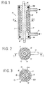
- a steam generator 10 which comprises a metal body 11, 18 in which is formed an elongated cavity 12, whose shape is of revolution and defined essentially by two walls cylindrical coaxial of the body 11, 18.
- the body 11, 18 can be produced using, on the one hand, a central metallic body of revolution 18, which can be produced by molding and having a central portion of reduced section to define the internal wall of the cavity 12, and on the other hand an external tube 11 which is attached around the central body 18 to form the external wall of the cavity 12.
- O-rings 18A, 18B are interposed between the central body 18 and the outer tube 11 to seal the cavity 12 relative to the outside.
- Tubes constituting connections 15 and 16 can be attached directly to the outer tube 11 and communicate with the cavity 12 by annular portions of section smaller than that of the cavity 12.
- the outer tube 11 can be metallic or, if necessary, made of plastic.
- An electrical resistance 14 which can be constituted by a standard central rectilinear element on which the central body 18 is overmolded, ensures the heating of the central body 18 and thereby of the cavity 12.
- the electrical resistance 14 can have a power by example of the order of 1000 to 2000 watts. Its length can be for example between 150 and 300 mm and its diameter can be for example from 6 to 7 mm.
- the central body 18 may itself have a diameter of the order of 15 to 20 mm in its narrowest part defining the internal wall of the cavity 12.
- the external tube 11 may itself have an outside diameter of the order of 35 to 40 mm and an internal diameter of the order of 25 to 30 mm, the thickness of the wall of the tube possibly being of the order of 2 mm.
- the steam generator 10 of Figures 1 and 2 can thus be very compact.
- the cavity 12 constituting the generator vaporization chamber 10 is filled with a lining of calibrated metal balls 13, for example made of stainless steel.
- the size of the balls 13 can be adapted to the applications and to the size of the generator 10.
- balls 13 having a diameter between 2 and 5 mm are very suitable.
- the balls 13 do not need to have a surface condition comparable to that of the balls for bearings for example, since these balls 13 only play a purely static role. Balls such as those used to polish the material, for example, are well suited.
- the role of the balls 13 is crucial insofar as these ensure a high concentration of heat, unlike wired elements for example, and define a very long divided path with broken lines between the various interstices arranged in staggered rows, this which promotes heat exchange. Furthermore, the beads do not stick to each other like mineral particles for example.
- connections 15, 16 can be provided with strainers to prevent the exit of the balls 13, or else elements in the form of a baffle or labyrinth as will be explained later with reference to particular examples of connections.
- the dimension e of the annular cavity 12 in the radial direction is such that this dimension is between 1.1d and 2d where d represents the diameter of the calibrated balls 13.
- d represents the diameter of the calibrated balls 13.
- the balls 13 maintain a temperature sufficient to continue to play their role in heating the new water introduced and steam can continue to form, unlike in the case where the cavity has a larger section in which the path is longer between the heating body and the balls furthest from this heating body.
- the transverse dimension e of the cavity 12 must be sufficient to allow the introduction of the balls 13 with play, but must remain less than twice the diameter of the balls to prevent more than two balls from being interposed between the central body 18 and the tube external 11.
- the transverse dimension j of the grooves formed in the central body 18 at the connections 15, 16 must itself remain smaller than the diameter d of the balls 13 to prevent them from escaping through the connections 15, 16.
- FIGS. 1 and 2 The embodiment of Figures 1 and 2 is particularly simple to perform, but can be the subject of many variants.
- Figure 3 we have shown an annular cavity 12 divided into two elementary cavities 12A, 12B by longitudinal partitions 19 oriented along a radius and connecting the central body 18 to the outer tube 11.
- the elementary cavities 12A, 12B can be mounted in parallel or so as to define a serial path as will be explained for example in the embodiment of FIGS. 4 and 5.
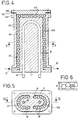
- FIGS 4 and 5 show another embodiment of a steam generator 10 according to the invention, in which two cavities 121, 122 of U-shaped section are juxtaposed around an electrical resistance 14 which itself has a U-shaped and is advantageously located in a median axial plane of the body 11 which also constitutes a plane of symmetry for the cavities 121, 122.
- the connections 15, 16 for introducing water and for discharging steam are located in the vicinity of a first front face of the steam generator, the connection 15 serving for the introduction of water into the cavity 121 and the connector 16 used for extracting steam from the cavity 122.
- the cavities 121 and 122 are themselves in communication in the vicinity of the second front face of the generator 10 by a channel 50.
- the second front face of the generator 10 may include a flange 11A delimiting the channel 50 and a cover 11B which can be fixed on the flange 11A with the interposition of a seal 11C and constitutes the external wall of the connecting channel 50.
- the cavities 121, 122 connected in series are filled with calibrated balls and the transverse dimension e of the cavities 221, 122 as well as of the connecting duct 50 is between 1, 1d and 2d where d represents the diameter of the balls 13.
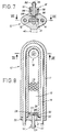
- Figures 7 and 8 show another possible embodiment in which the metal body 11 is made in one piece by overmolding the heating resistor 14 in a U shape placed in a median axial plane of the cavity 12, around that -this.
- the cavity 12, which has a flattened rectangular section, is lined with balls as in all the embodiments previously described, and the small dimension e of the rectangular section of the cavity 12 has a value between 1.1d and 2d where d represents the diameter of the balls.
- the connector 15 ′ comprises a nozzle 22 defining a blind central channel 23 which opens out through one or more lateral orifices 29 in an annular groove 26 which communicates with the cavity 12 by a peripheral annular passage 28 of width less than the diameter of the balls 13 (for example having a width of the order of 1.5 mm if the biles have a diameter of 2 mm) .
- the connector 15 ′ comprises a front part 20 in the form of a plate which is fixed for example by screws 21A to the part 11A of the body 11, and a cylindrical part which penetrates into an opening formed at one end of the cavity 12.
- the part cylindrical of the connector 15 ′ comprises portions 21, 24, 27 of different diameters to define with the cylindrical wall of the cavity 12 the peripheral annular passages 26, 28 for injecting liquid.
- a seal 25 can be interposed between the connector 15 'and the orifice of the cavity 12.
- FIGS. 7 and 8 also show an example of a steam extraction connection 16 ′ arranged on the side opposite to the water injection connection 15 ′.
- the connector 16 ′ comprises a nozzle 32 pierced with a central orifice 33, a stop collar 31 coming to bear against an end wall of the body 11A with the interposition of a seal 35, and a cylindrical body 34, which can be screwed in an orifice formed at the end of the cavity 12, on the side opposite the connector 15 '.
- the cylindrical body 34 is closed by a wall 37 at its free end so that the central channel 33 does not open axially into the cavity 12.
- One or more slots 39 are formed in the end part of the body 34 which is in the vicinity of the cavity 12 to ensure introduction of the steam into the central channel 33. This embodiment prevents balls from being expelled through the connector 16 ′, the thickness of the slots 39 being naturally less than the diameter of the balls 13.
- the vapor extraction connector 16 is arranged perpendicular to the axis of the cavity 12, and is located laterally in the hottest zone of the cavity 12.
- the cylindrical body 34 of the connector 16 of Figure 7 is simply screwed into a side channel which opens into the cavity 12 perpendicular to the axis thereof.
- the end of the body 34 in which the slots 39 or equivalent lateral orifices are formed, may have a reduced section to define an annular groove 36 for collecting steam at the base of said lateral channel, in cases where the body 34 must not not penetrate too far into the cavity 12.
- FIG. 7 shows a thermostat 40 which can be placed in the coldest zone on the side of the body 11 in the vicinity of the water inlet connector 15, and makes it possible to control the supply of the heating resistor 14.
- the steam generator according to the invention has a simple structure which both facilitates manufacture and improves the operation of the device and its reliability while allowing, if necessary, a very convenient descaling, the balls 13 constituting robust elements and inexpensive which can be easily removed from the cavity 12 for cleaning or exchange.
- the invention avoids the use of movable elements such as valves, valves, springs.
- the generator according to the invention is suitable for domestic or professional uses, with vapor flow rates which can be of the order of 60 g / mm, and can be either used as a separate annex element, or, because of its compactness, incorporated into a device such as an iron.
- the steam generator according to the invention can advantageously be produced according to an embodiment, as illustrated in FIGS. 9 and 10, or 11 and 12, in which the cavity 12 comprises first and second separate flat individual cavities 121, 122 superimposed and placed in communication at one of their ends by a communication channel 50 resp. 150 to define two vaporization chambers operating in series.
- the two superimposed elementary cavities 121, 122 each have an essentially rectangular section whose small dimension e is between 1.1d and 2d where d represents the diameter of the balls 13 and can be produced in a molded body 11, as in the case of the embodiment of Figures 7 and 8, with a resistor 14 in U embedded in the body 11, so that the size of the steam generator 10 can remain reduced.
- the lower cylindrical cavity 121 is supplied with water at its front end opposite to the curvature of the U-shaped resistor 14, through a connector 15 'which can be similar to the connector 15' described with reference to FIG. 8.
- a communication channel 50 perpendicular to the axis of the steam generator ensures communication between the two cylindrical cavities 121, 122 in the vicinity of their end situated on the side of the curvature of the U-shaped resistor 14.
- a connector 16 'for steam extraction can be similar to the connector 16 in Figure 7 and can be arranged axially at the front end of the upper cylindrical cavity 122 immediately above of the water injection fitting 15 '.
- connections 15 'and 16' which can be produced for example under the plugs closing the opening of the superimposed elementary cavities 121, 122, are located at the same front end of the steam generator 10, which can simplify the production, the electrical connection of the resistor 14 can also be made on this same front end in the vicinity of which it is also advantageously possible to place the thermostat 40.
- the upper elementary cavity 122 is filled with calibrated metal balls 13 like the cavities 12 of the previous embodiments.
- the lower elementary cavity 121 which serves as an airlock trapping any excess water supply relative to the heating power of the resistor 14, is also filled with calibrated metal balls 13.
- Figures 11 and 12 is very similar to that of Figures 9 and 10 and differs only in the type of fitting used.
- a single plate 60 carrying the connections 15 'and 16' of water supply and steam extraction is attached to the front end of the steam generator 10 opposite the curvature of the resistance in U 14, and fixed to the body 11 by connecting means 61 such as screws.
- the nozzles 22 and 32 of the connections 15 ′ and 16 ′ for injecting water and extracting steam consist of tubes extending inside the elementary cavities 121 and 122 respectively until they reach the end of the steam generator opposite the plate 60. Furthermore, the communication channel 150 between the lower elementary cavity 121 and the upper elementary cavity 122 is itself located on the side of the front plate 60.
- the water introduced by the tube 22 opens into the lower cavity 121 in the vicinity of the curved part of the resistor 14, having already been slightly heated, the vapor formed in the lower cavity 121 passes into the upper cavity 122 through the passage 150 which is located near the plate 60, but without direct communication with the tubes 22, 32, and the vapor is finally extracted from the upper cavity 122 through the tube 32 which originates in the vicinity of e the hottest area of the cavity 122 located near the curvature of the resistor 14, and is extracted through the part of the tube 32 forming a nozzle.
- the various embodiments of the invention are very easy to manufacture and do not require precision machining.
- the filling or emptying of the cavity 12 or of the cavities 121, 122 into balls 13 can be done simply from the orifices provided for the fittings 15, 16.
Landscapes
- Engineering & Computer Science (AREA)
- Life Sciences & Earth Sciences (AREA)
- Sustainable Development (AREA)
- Sustainable Energy (AREA)
- Physics & Mathematics (AREA)
- Thermal Sciences (AREA)
- Mechanical Engineering (AREA)
- General Engineering & Computer Science (AREA)
- Devices For Medical Bathing And Washing (AREA)
- Irons (AREA)
- Organic Low-Molecular-Weight Compounds And Preparation Thereof (AREA)
- Noodles (AREA)
Claims (15)
- Schnelldampferzeuger mit einem Gehäuse (11) aus Metall, das einen länglichen Hohlraum (12) umgrenzt, der eine Verdampfungskammer bildet, mindestens einem Heizelement (14), das im genannten Gehäuse (11) in der Nähe des Hohlraums (12) angeordnet ist, einem ersten Anschluß (15) zum Einspritzen von Flüssigkeit in den Hohlraum (12), einem zweiten Anschluß (16) zur Entnahme des Dampfes, der im Hohlraum (12) gebildet ist, und statischen Mitteln (13) aus wärmeleitfähigem Material, die im Hohlraum (12) angeordnet sind, um den Verdampfungsgrad der Flüssigkeit zu erhöhen, die in den Hohlraum (12) eingeführt wurde,
dadurch gekennzeichnet, daß die statischen Mittel ein Futter aufweisen, das aus einer Gruppe von kalibrierten Metallkugeln (13) gebildet ist, die einander berühren, und daß der Hohlraum (12) in Querrichtung eine Abmessung (e) aufweist, die zwischen 1,1d und 2d liegt, wobei d den Durchmesser der kalibrierten Metallkugeln (13) darstellt. - Dampferzeuger nach Anspruch 1, dadurch gekennzeichnet, daß die kalibrierten Metallkugeln (13) einen Durchmesser aufweisen, der zwischen etwa zwischen 2 und 5 mm liegt.
- Dampferzeuger nach irgendeinem der Ansprüche 1 und 2, dadurch gekennzeichnet, daß das Heizelement (14) von einem elektrischen Widerstand in Form eines mittigen Kernes gebildet ist, der in das Gehäuse (11) eingelassen ist.
- Dampferzeuger nach Anspruch 3, dadurch gekennzeichnet, daß der Hohlraum (12) im wesentlichen ringförmig und koaxial zum Heizelement (14) verläuft.
- Dampferzeuger nach Anspruch 4, dadurch gekennzeichnet, daß der Hohlraum (12) durch in Bezug auf das Gehäuse (11) längsverlaufende, radiale Trennwände in mehrere Elementarhohlräume (12A, 12B) unterteilt ist.
- Dampferzeuger nach Anspruch 1 oder 2, dadurch gekennzeichnet, daß der Hohlraum (12) eine längliche Form mit rechteckigem Querschnitt aufweist.
- Dampferzeuger nach Anspruch 1 oder 2, dadurch gekennzeichnet, daß der Hohlraum (12) eine längliche Form mit U-förmigem Querschnitt aufweist.
- Dampferzeuger nach einem der Ansprüche 1, 2, 6 und 7, dadurch gekennzeichnet, daß das Heizelement (14) von einem U-förmigen elektrischen Widerstand gebildet ist, der in das Gehäuse (11) eingelassen ist.
- Dampferzeuger nach irgendeinem der Ansprüche 1 bis 8, dadurch gekennzeichnet, daß der Hohlraum (12) mindestens erste und zweite, getrennte Elementarhohlräume (121, 122) aufweist, die sich in der Nähe des Heizelements (14) erstrecken und an einem ihrer Enden miteinander in Verbindung gesetzt sind, um in Reihe angeordnete Verdampfungskammern zu bilden.
- Dampferzeuger nach Anspruch 9, dadurch gekennzeichnet, daß der erste und zweite Anschluß (15', 6') in der Nähe ein und derselben Frontfläche des Erzeugers angeordnet sind, daß der erste Anschluß (15') in der Nähe eines ersten, axialen Endes des ersten Elementarhohlraums (121) einmündet, daß der zweite Anschluß (16') in der Nähe eines ersten axialen Endes des zweiten Elementarhohlraums (122) einmündet, das nahe dem ersten axialen Ende des ersten Elementarhohlraums (121) angeordnet ist, und daß der erste und zweite Elementarhohlraum (121, 122) miteinander durch einen Verbindungskanal (50; 150) in Verbindung stehen, der in der Nähe der zweiten axialen Enden des genannten ersten und zweiten Elementarhohlraums (121, 122) angeordnet ist.
- Dampferzeuger nach irgendeinem der Ansprüche 1 bis 10, dadurch gekennzeichnet, daß das Gehäuse (11) einen geformten Kasten aufweist, in den ein elektrischer Heizwiderstand (14) eingelassen ist, der im wesentlichen in einer Axialebene des Hohlraums (12) gelegen ist.
- Dampferzeuger nach irgendeinem der Ansprüche 1 bis 11, dadurch gekennzeichnet, daß der erste Anschluß (15, 15') eine mittige Flüssigkeitszuführung aufweist, die über eine Ringnut (26, 28) hinweg seitlich in den Hohlraum (12) einmündet.
- Dampferzeuger nach irgendeinem der Ansprüche 1 bis 12, dadurch gekennzeichnet, daß der zweite Anschluß (16, 16') einen mittigen Dampfaustritt aufweist, der über eine Ringnut (36) hinweg mit dem Hohlraum (12) in Berührung steht.
- Dampferzeuger nach irgendeinem der Ansprüche 1 bis 13, dadurch gekennzeichnet, daß er ein Thermostat (40) aufweist, das am Gehäuse (11) im kältesten Bereich angebracht ist, in dessen Nähe auch der erste Anschluß (15, 15') gelegen ist.
- Dampferzeuger nach irgendeinem der Ansprüche 3 und 4, dadurch gekennzeichnet, daß das Gehäuse (11) einen mittigen Kern (18) aufweist, der längs des Hohlraums (12) einen verringerten Querschnitt aufweist, sowie eine äußere, rohrförmige Umhüllung, die rund um den mittigen Kern (18) angesetzt ist und die Außenwand des ringförmigen Hohlraums (12) bildet.
Applications Claiming Priority (2)
| Application Number | Priority Date | Filing Date | Title |
|---|---|---|---|
| FR9213695A FR2698155B1 (fr) | 1992-11-13 | 1992-11-13 | Générateur de vapeur instantané à chauffage électrique. |
| FR9213695 | 1992-11-13 |
Publications (2)
| Publication Number | Publication Date |
|---|---|
| EP0597748A1 EP0597748A1 (de) | 1994-05-18 |
| EP0597748B1 true EP0597748B1 (de) | 1997-04-23 |
Family
ID=9435532
Family Applications (1)
| Application Number | Title | Priority Date | Filing Date |
|---|---|---|---|
| EP93402618A Expired - Lifetime EP0597748B1 (de) | 1992-11-13 | 1993-10-26 | Schnelldampferzeuger |
Country Status (4)
| Country | Link |
|---|---|
| EP (1) | EP0597748B1 (de) |
| AT (1) | ATE152229T1 (de) |
| DE (1) | DE69310097T2 (de) |
| FR (1) | FR2698155B1 (de) |
Families Citing this family (5)
| Publication number | Priority date | Publication date | Assignee | Title |
|---|---|---|---|---|
| US5949958A (en) * | 1995-06-07 | 1999-09-07 | Steris Corporation | Integral flash steam generator |
| DE102005058592B4 (de) * | 2005-12-07 | 2008-11-06 | Miwe Michael Wenz Gmbh | Dampferzeuger |
| CN100414033C (zh) * | 2006-02-09 | 2008-08-27 | 徐建群 | 一种储汽式汽化锅 |
| CN105202511B (zh) * | 2015-10-26 | 2017-10-13 | 中国船舶重工集团公司第七一八研究所 | 密闭空间水蒸气连续发生装置 |
| DE102022209108A1 (de) * | 2022-09-01 | 2024-03-07 | E.G.O. Elektro-Gerätebau GmbH | Heizeinrichtung zum Erhitzen von Flüssigkeit und Verfahren zum Betrieb einer Heizeinrichtung |
Family Cites Families (7)
| Publication number | Priority date | Publication date | Assignee | Title |
|---|---|---|---|---|
| DE32401C (de) * | P. L. buisson PERE, J. A. BUISSON FILS und L. BUISSON FILS in St. Etienne, i Loire, Frankreich | Füllung eines Dampferzeugers mit Eisenstücken | ||
| BE350513A (de) * | ||||
| CH47172A (fr) * | 1908-11-07 | 1910-06-01 | Francois Trachsel Eugene | Chaudière à vapeur |
| GB742600A (en) * | 1953-03-04 | 1955-12-30 | Gen Electric Co Ltd | Improvements in or relating to thermal storage steam generators |
| DE1146602B (de) * | 1960-09-26 | 1963-04-04 | Klaus Fischer | Periodisch betriebener, mit einer Waerme-speichereinrichtung versehener, elektrisch beheizter Wasserdampferzeuger |
| DE1601224A1 (de) * | 1967-10-14 | 1969-10-02 | Meese Fa Fr | Waermetauscher |
| FR2123983A5 (de) * | 1971-02-04 | 1972-09-15 | Castany Ferre Jose |
-
1992
- 1992-11-13 FR FR9213695A patent/FR2698155B1/fr not_active Expired - Fee Related
-
1993
- 1993-10-26 AT AT93402618T patent/ATE152229T1/de not_active IP Right Cessation
- 1993-10-26 EP EP93402618A patent/EP0597748B1/de not_active Expired - Lifetime
- 1993-10-26 DE DE69310097T patent/DE69310097T2/de not_active Expired - Fee Related
Also Published As
| Publication number | Publication date |
|---|---|
| FR2698155B1 (fr) | 1995-02-03 |
| EP0597748A1 (de) | 1994-05-18 |
| ATE152229T1 (de) | 1997-05-15 |
| FR2698155A1 (fr) | 1994-05-20 |
| DE69310097T2 (de) | 1997-11-20 |
| DE69310097D1 (de) | 1997-05-28 |
Similar Documents
| Publication | Publication Date | Title |
|---|---|---|
| EP1009270B1 (de) | Infusionsgruppe für getränkespender von aromatischen getränken mit einem boiler | |
| EP2185046B1 (de) | Heisswasserbereiter für eine getränkezubereitungsmaschine | |
| EP2931093B1 (de) | Heisswasserbereiter für getränkezubereitungsautomat | |
| EP0963532B1 (de) | Dampferzeuger | |
| BE1001097A5 (fr) | Rechauffeur tubulaire a ailettes. | |
| EP0766526A1 (de) | Vorrichtung zur bereitung von heisswasser oder dampf | |
| FR2855359A1 (fr) | Dispositif de chauffage d'un liquide pour appareil electromenager, appareil electromenager equipe d'un tel dispositif. | |
| WO2007039683A1 (fr) | Dispositif de chauffage de liquide pour appareil electromenager | |
| FR2878419A1 (fr) | Distributeur de boissons infusees comprenant une chaudiere amelioree et son procede de fabrication | |
| EP3246459A1 (de) | Dampfbügeleisen mit heizkörper, der eine dampfkammer und eine bügelfläche umfasst, die in wärmeverbindung mit dem heizkörper steht | |
| WO2008099266A1 (fr) | Appareil de repassage a vapeur comportant un reservoir d' eau en communication directe avec une chambre d' ebullition | |
| EP3266927B1 (de) | Bügeleisen, das einen heizkörper in thermischem kontakt mit einer bügelplatte umfasst | |
| EP0597748B1 (de) | Schnelldampferzeuger | |
| FR2609437A1 (fr) | Dispositif de chauffage d'un liquide de lave-glace, notamment pour vehicule automobile | |
| EP2115210A1 (de) | Bügelvorrichtung mit siedekammer, aus der der erzeugte dampf frei in richtung eines bügelgeräts entweichen kann | |
| EP0275776B1 (de) | Kontrollgerät für die Überhitzung und Verkalkung eines Flüssigkeitserhitzers und Gerät, versehen mit einem solchen Kontrollgerät | |
| EP0329508B1 (de) | Zentralheizung mit Brauchwasserkreislauf | |
| EP4458204A1 (de) | Dampfhaarpflegegerät mit mehreren dichtungen | |
| EP1565690B1 (de) | Wärmetauscher und brauchwassererhitzer | |
| FR3070404B1 (fr) | Appareil de repassage comportant une base reliee par un cordon a un fer a repasser | |
| EP4299824B1 (de) | Elektrisches haushaltsgerät zum bügeln und/oder glätten mit mindestens zwei durch eine verbindungsleitung verbundenen sprühkammern | |
| FR2532583A1 (fr) | Dispositif d'injection et de chauffage a cartouche pour un distributeur d'injection a chenaux de coulee chaude | |
| EP4299825A1 (de) | Elektrisches haushaltsgerät zum bügeln und/oder glätten mit einer vorrichtung zum zurückhalten von dampfgetragenen kalkpartikeln | |
| WO2026008721A1 (fr) | Dispositif de traitement de la chevelure, notamment de bouclage et/ou de lissage, à vapeur | |
| FR3140245A1 (fr) | Chambre de vaporisation pour appareil de coiffure à diffusion de vapeur. |
Legal Events
| Date | Code | Title | Description |
|---|---|---|---|
| PUAI | Public reference made under article 153(3) epc to a published international application that has entered the european phase |
Free format text: ORIGINAL CODE: 0009012 |
|
| AK | Designated contracting states |
Kind code of ref document: A1 Designated state(s): AT BE CH DE ES FR GB IT LI NL SE |
|
| 17P | Request for examination filed |
Effective date: 19941114 |
|
| GRAG | Despatch of communication of intention to grant |
Free format text: ORIGINAL CODE: EPIDOS AGRA |
|
| 17Q | First examination report despatched |
Effective date: 19960125 |
|
| GRAH | Despatch of communication of intention to grant a patent |
Free format text: ORIGINAL CODE: EPIDOS IGRA |
|
| GRAH | Despatch of communication of intention to grant a patent |
Free format text: ORIGINAL CODE: EPIDOS IGRA |
|
| GRAA | (expected) grant |
Free format text: ORIGINAL CODE: 0009210 |
|
| RAP1 | Party data changed (applicant data changed or rights of an application transferred) |
Owner name: SUPERBA S.A. |
|
| AK | Designated contracting states |
Kind code of ref document: B1 Designated state(s): AT BE CH DE ES FR GB IT LI NL SE |
|
| PG25 | Lapsed in a contracting state [announced via postgrant information from national office to epo] |
Ref country code: NL Effective date: 19970423 Ref country code: ES Free format text: THE PATENT HAS BEEN ANNULLED BY A DECISION OF A NATIONAL AUTHORITY Effective date: 19970423 Ref country code: AT Effective date: 19970423 |
|
| REF | Corresponds to: |
Ref document number: 152229 Country of ref document: AT Date of ref document: 19970515 Kind code of ref document: T |
|
| REG | Reference to a national code |
Ref country code: CH Ref legal event code: EP |
|
| REF | Corresponds to: |
Ref document number: 69310097 Country of ref document: DE Date of ref document: 19970528 |
|
| GBT | Gb: translation of ep patent filed (gb section 77(6)(a)/1977) |
Effective date: 19970627 |
|
| PG25 | Lapsed in a contracting state [announced via postgrant information from national office to epo] |
Ref country code: SE Effective date: 19970723 |
|
| NLV1 | Nl: lapsed or annulled due to failure to fulfill the requirements of art. 29p and 29m of the patents act | ||
| PG25 | Lapsed in a contracting state [announced via postgrant information from national office to epo] |
Ref country code: LI Free format text: LAPSE BECAUSE OF NON-PAYMENT OF DUE FEES Effective date: 19971031 Ref country code: CH Free format text: LAPSE BECAUSE OF NON-PAYMENT OF DUE FEES Effective date: 19971031 Ref country code: BE Free format text: LAPSE BECAUSE OF NON-PAYMENT OF DUE FEES Effective date: 19971031 |
|
| PLBE | No opposition filed within time limit |
Free format text: ORIGINAL CODE: 0009261 |
|
| STAA | Information on the status of an ep patent application or granted ep patent |
Free format text: STATUS: NO OPPOSITION FILED WITHIN TIME LIMIT |
|
| 26N | No opposition filed | ||
| BERE | Be: lapsed |
Owner name: S.A. SUPERBA Effective date: 19971031 |
|
| REG | Reference to a national code |
Ref country code: CH Ref legal event code: PL |
|
| REG | Reference to a national code |
Ref country code: FR Ref legal event code: TP |
|
| REG | Reference to a national code |
Ref country code: GB Ref legal event code: IF02 |
|
| PGFP | Annual fee paid to national office [announced via postgrant information from national office to epo] |
Ref country code: DE Payment date: 20041007 Year of fee payment: 12 |
|
| PGFP | Annual fee paid to national office [announced via postgrant information from national office to epo] |
Ref country code: GB Payment date: 20041011 Year of fee payment: 12 |
|
| PG25 | Lapsed in a contracting state [announced via postgrant information from national office to epo] |
Ref country code: IT Free format text: LAPSE BECAUSE OF NON-PAYMENT OF DUE FEES;WARNING: LAPSES OF ITALIAN PATENTS WITH EFFECTIVE DATE BEFORE 2007 MAY HAVE OCCURRED AT ANY TIME BEFORE 2007. THE CORRECT EFFECTIVE DATE MAY BE DIFFERENT FROM THE ONE RECORDED. Effective date: 20051026 Ref country code: GB Free format text: LAPSE BECAUSE OF NON-PAYMENT OF DUE FEES Effective date: 20051026 |
|
| PG25 | Lapsed in a contracting state [announced via postgrant information from national office to epo] |
Ref country code: DE Free format text: LAPSE BECAUSE OF NON-PAYMENT OF DUE FEES Effective date: 20060503 |
|
| GBPC | Gb: european patent ceased through non-payment of renewal fee |
Effective date: 20051026 |
|
| PGFP | Annual fee paid to national office [announced via postgrant information from national office to epo] |
Ref country code: FR Payment date: 20061031 Year of fee payment: 14 |
|
| REG | Reference to a national code |
Ref country code: FR Ref legal event code: ST Effective date: 20080630 |
|
| PG25 | Lapsed in a contracting state [announced via postgrant information from national office to epo] |
Ref country code: FR Free format text: LAPSE BECAUSE OF NON-PAYMENT OF DUE FEES Effective date: 20071031 |