EP0597757A2 - Antenne de vitrage pour véhicule automobile - Google Patents
Antenne de vitrage pour véhicule automobile Download PDFInfo
- Publication number
- EP0597757A2 EP0597757A2 EP93402701A EP93402701A EP0597757A2 EP 0597757 A2 EP0597757 A2 EP 0597757A2 EP 93402701 A EP93402701 A EP 93402701A EP 93402701 A EP93402701 A EP 93402701A EP 0597757 A2 EP0597757 A2 EP 0597757A2
- Authority
- EP
- European Patent Office
- Prior art keywords
- antenna
- glazing
- conductor
- conductive surface
- coaxial cable
- Prior art date
- Legal status (The legal status is an assumption and is not a legal conclusion. Google has not performed a legal analysis and makes no representation as to the accuracy of the status listed.)
- Granted
Links
Images

Classifications
-
- B—PERFORMING OPERATIONS; TRANSPORTING
- B32—LAYERED PRODUCTS
- B32B—LAYERED PRODUCTS, i.e. PRODUCTS BUILT-UP OF STRATA OF FLAT OR NON-FLAT, e.g. CELLULAR OR HONEYCOMB, FORM
- B32B17/00—Layered products essentially comprising sheet glass, or glass, slag, or like fibres
- B32B17/06—Layered products essentially comprising sheet glass, or glass, slag, or like fibres comprising glass as the main or only constituent of a layer, next to another layer of a specific material
- B32B17/10—Layered products essentially comprising sheet glass, or glass, slag, or like fibres comprising glass as the main or only constituent of a layer, next to another layer of a specific material of synthetic resin
- B32B17/10005—Layered products essentially comprising sheet glass, or glass, slag, or like fibres comprising glass as the main or only constituent of a layer, next to another layer of a specific material of synthetic resin laminated safety glass or glazing
- B32B17/10009—Layered products essentially comprising sheet glass, or glass, slag, or like fibres comprising glass as the main or only constituent of a layer, next to another layer of a specific material of synthetic resin laminated safety glass or glazing characterized by the number, the constitution or treatment of glass sheets
- B32B17/10036—Layered products essentially comprising sheet glass, or glass, slag, or like fibres comprising glass as the main or only constituent of a layer, next to another layer of a specific material of synthetic resin laminated safety glass or glazing characterized by the number, the constitution or treatment of glass sheets comprising two outer glass sheets
-
- H—ELECTRICITY
- H01—ELECTRIC ELEMENTS
- H01Q—ANTENNAS, i.e. RADIO AERIALS
- H01Q1/00—Details of, or arrangements associated with, antennas
- H01Q1/12—Supports; Mounting means
- H01Q1/1271—Supports; Mounting means for mounting on windscreens
Definitions
- the present invention relates to a glazing antenna for motor vehicles, in which, on the surface of a glazing or inside thereof, is installed an antenna conductor whose antenna base, connected to the conductor central of a coaxial cable, is arranged in the vicinity of a conductive surface provided in the marginal region of the glazing and connected to the outer conductor of the coaxial cable.
- Antenna structures of this type are suitable, in particular, as transmitting antennas for radio, in particular, as an antenna for radiotelephone communications in the digital network.
- the antenna conductor consists of a rectilinear conductor having a free end which extends from from the edge of the glazing in the field of vision of this glazing.
- the antenna conductor and the conductive surface serving as a reference plane can be applied by printing and baked, like the heating conductors of heated glazing, on the surface of the glass facing the interior of the vehicle interior.
- the resonant frequency depends to a certain extent on the glazing materials and the tolerances geometric when mounting this glazing. Consequently, in the case of these known antennas, it is, moreover, also necessary to retune them after mounting, if their efficiency is below an optimal value.
- the object of the invention is to produce a glazing antenna of the specified type in which the dependence of the resonant frequency on the materials used as well as the geometric and mechanical tolerances of the glazing and of the window frame of the vehicle body is significantly reduced.
- the antenna conductor has the shape of a loop and is connected at its end to the conductive surface.
- the antenna conductor of the antenna structure according to the invention also has the form of a folded single-pole antenna conductor, one end of which is connected directly to the conductive surface forming the reference potential.
- the antenna structure according to the invention is essentially insensitive to mounting tolerances, because, following its direct connection to the conductive surface, it can be grounded in a well defined manner.
- it has the advantage that, following the possibility of varying the width of the loop, it offers the additional latitude of impedance matching via the width of the loop.
- Figs. 1 and 2 illustrate a monolithic glazing 1 which has undergone thermal toughening, which is used as a rear window and which is provided with a network of heating conductors.
- the network of heating conductors comprises a row of heating conductors 2 which extend over the entire width of the glazing, as well as two bus conductors 3, 4 arranged laterally at the edges of the glazing.
- the heating conductors 2 and the omnibus conductors 3, 4 are made of an electrically conductive baking ink, termed conductive silver, which is applied by screen printing to the surface of the glass and which is baked in the surface of the glass. during the bending and / or quenching process.
- an antenna structure suitable for radiocommunications at a frequency situated in the range of 900 MHz.
- This antenna structure is made of the same material as the heating conductors 2 and the bus bars 3 and 4 and is printed on the surface of the glass during the same printing operation as these, then also baked at the bending or quenching temperature.
- the antenna structure consists of the antenna conductor 6 in the form of a loop about 0.5 mm wide with an antenna base 7 having the shape of an enlarged surface, to which the central conductor of the antenna is connected. supply cable in the form of a coaxial cable.
- the length L of the conductor loop is, for example, 120 mm while the width B of this loop, that is to say the distance of the two rectilinear conductor segments parallel to each other is about 10 mm.
- the loop-shaped antenna conductor 6 is, in the case shown, placed in an upper corner area of the glazing 1 and forms an angle of approximately 45 ° with the horizontal, but it will of course it can be installed in any other place of the glazing and be oriented essentially at any angle with respect to the horizontal. When conditions allow, the antenna conductor 6 is preferably oriented at right angles to the horizontal.
- the electrical counterweight to the antenna conductor 6 in the form of a folded single-pole antenna is formed by the conductive surface 8 which also consists of the same electrically conductive cooking ink as the heating conductor 2 and the antenna conductor 6 , and which was also applied to the surface of the glass during the same process step as the other conductive structures.
- the conductive surface 8 is formed from strips of 1 to 3 cm in width along the edge of the glazing. The length 1 of this strip-shaped surface 8 is not critical, but should advantageously reach at least about 120 mm.
- the conductive surface 8 has a flat projection 9 oriented towards the surface of the glazing which, at its end, forms an annular surface 10.
- the annular surface 10 is provided with a radially oriented slot 11 in which the conductor is arranged.
- antenna 6 whose antenna base 7 is located inside the annular surface 10 concentrically thereto.
- the end zone 6 ′ of the loop-shaped antenna conductor 6 is connected to the flat projection 9 of the conductive surface 8.
- the network of heating conductors and the antenna conductor structure are located on the face of the glazing facing the interior of the passenger compartment.
- the conductive surface 8 is connected over an extended area to the adhesive bead and, via the adhesive bead , to the metal mounting flange of the automobile body. Since the current adhesive materials currently present a certain electrical conductivity, the conductive surface 8 is in this way electrically connected to the body. In this way, the antenna is connected directly to the body.
- a laminated glass pane 15 is shown with a wire antenna designed according to the invention.
- the laminated glass pane 15 consists of the individual glass sheet 16 facing outward, in the assembled state, the individual glass sheet 17 facing inward of the passenger compartment and the thermoplastic intermediate layer 18 connecting the two individual glass sheets 16 and 17 to each other.
- the inner individual glass sheet 17 is provided, at its lower edge, with a notch 19.
- the thermoplastic intermediate layer 18 there is a metal wire 20 in the form of a loop, that is to say in the form of antenna single-pole folded, the two ends of which protrude in the region of the marginal notch 19.
- the length L of the wire loop 20 is again a function of the transmission frequency and reaches, for example, again 120 mm while the width B of the wire loop 20 is again about 10 mm.
- an electrically conductive surface in the form of a strip 23.
- it may be, for example, a layer an ink or a cooking ink both conductive of electricity.
- the electrically conductive surface 23 is however advantageously made of a foil sheet which is firmly and permanently bonded to the surface 23 of the glass.
- the surface dimensions of the electrically conductive surface 23 are again not critical, but the length of the foil sheet should be at least about 120 mm.
- the antenna is certainly installed at the lower edge of the glazing, but it can obviously be installed in any other location of laminated glass. It has been found that particularly good results can be obtained when the antenna is installed in the upper marginal zone of the laminated glass glazing.
- an antenna supply cable 25 having the form of a coaxial cable.
- the first end of the conductor loop 20, i.e. the base of the antenna, is connected to the central conductor 26 of the coaxial cable and the other end 20 'is connected to the external conductor 27 of the coaxial cable 25 and to the conductive surface 23.
- a foil strip 28 is connected by soldering on the one hand to the foil foil 23 and on the other hand to the outer conductor 27 of the coaxial cable 25.
- the marginal notch 19 is then filled with a suitable hardening polymer and is sealed to protect the place of the connection and fix the coaxial cable 25 to the glazing.
- the electrically conductive surface 23 is again connected over a large area, in an electrically conductive manner, by means of the adhesive bead to the metal frame. of the body, so that the antenna receives a well-defined reference potential.
Landscapes
- Details Of Aerials (AREA)
- Support Of Aerials (AREA)
- Fittings On The Vehicle Exterior For Carrying Loads, And Devices For Holding Or Mounting Articles (AREA)
Abstract
Description
- La présente invention concerne une antenne de vitrage pour véhicules automobiles, dans laquelle, sur la surface d'un vitrage automobile ou à l'intérieur de celui-ci, est installé un conducteur d'antenne dont la base d'antenne, connectée au conducteur central d'un câble coaxial, est disposée au voisinage d'une surface conductrice prévue dans la région marginale du vitrage et connectée au conducteur extérieur du câble coaxial.
- Des structures d'antenne de ce type conviennent, en particulier, comme antennes d'émission pour la radio, en particulier, comme antenne pour les communications radiotéléphoniques dans le réseau numérique. Pour que la puissance d'émission rayonne à partir de l'antenne, il faut que de telles antennes soient accordées de manière précise. A cet effet, elles ont besoin d'un plan de référence défini auquel tous les paramètres électriques sont rapportés. A titre de plan de référence, une couche conductrice de l'électricité en forme de bande est, dès lors, appliquée directement sur la région marginale du vitrage.
- Une structure d'antenne de ce type est connue par le document WO 88/09569. Dans cette antenne connue, qui est prévue en tant qu'antenne radio de préférence pour le domaine des fréquences compris entre 890 et 960 MHz, le conducteur d'antenne est constitué d'un conducteur rectiligne présentant une extrémité libre qui s'étend à partir du bord du vitrage dans le champ de vision de ce vitrage. Le conducteur d'antenne et la surface conductrice servant de plan de référence peuvent être appliqués par impression et cuits, comme les conducteurs chauffants des vitrages chauffants, sur la surface du verre tournée vers l'intérieur de l'habitacle du véhicule.
- En outre, dans le cas de cette structure d'antenne connue, la fréquence de résonance dépend dans une certaine mesure des matières du vitrage et des tolérances géométriques lors du montage de ce vitrage. Par conséquent, dans le cas de ces antennes connues, il est, en outre, également nécessaire de les réaccorder après le montage, si leur efficacité est en deçà d'une valeur optimale.
- L'invention a pour but de réaliser une antenne de vitrage du type spécifié dans laquelle la dépendance de la fréquence de résonance à l'égard des matières utilisées ainsi que des tolérances géométriques et mécaniques du vitrage et du cadre de fenêtre de la carrosserie du véhicule soit sensiblement réduite.
- Suivant l'invention, ce but est réalisé par le fait que le conducteur d'antenne a la forme d'une boucle et est connecté a son extrémité à la surface conductrice.
- Le conducteur d'antenne de la structure d'antenne conforme à l'invention a également la forme d'un conducteur d'antenne replié unipolaire dont une extrémité est connectée directement à la surface conductrice formant le potentiel de référence. La structure d'antenne conforme à l'invention est en substance insensible à l'égard des tolérances de montage, parce que, suite à sa connexion directe à la surface conductrice, elle peut être mise à la masse de manière bien définie. En outre, elle a l'avantage que, suite à la possibilité de faire varier la largeur de la boucle, elle offre la latitude supplémentaire d'une adaptation d'impédance via la largeur de la boucle.
- Des développements et des perfectionnements avantageux de l'invention ressortiront des revendications dépendantes et de la description suivante de divers exemples de réalisation donnés avec référence aux dessins annexés, dans lesquels :
- la Fig. 1 illustre une lunette arrière en verre de sécurité présentant une structure d'antenne imprimée et cuite sur une surface;
- la Fig. 2 est une vue à plus grande échelle d'un détail de la Fig. 1;
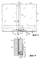
- la Fig. 3 est une vue en élévation d'un pare-brise en verre feuilleté avec un fil d'antenne incorporé, et
- la Fig. 4 est une vue en coupe suivant la ligne IV-IV de la Fig. 3.
- Les Fig. 1 et 2 illustrent un vitrage monolithique 1 qui a subi une trempe thermique, qui est utilisé comme lunette arrière et qui est pourvu d'un réseau de conducteurs chauffants. Le réseau de conducteurs chauffants comprend une rangée de conducteurs chauffants 2 qui s'étendent sur toute la largeur du vitrage, ainsi que deux conducteurs omnibus 3, 4 disposés latéralement aux bords du vitrage. Les conducteurs chauffants 2 et les conducteurs omnibus 3, 4 sont faits d'une encre à cuire conductrice de l'électricité, qualifiée d'argent conducteur, qui est appliquée par sérigraphie sur la surface du verre et qui est cuite dans la surface du verre au cours du processus de bombage et/ou de trempe.
- Dans la région supérieure du vitrage 1, outre le réseau de conducteurs chauffants, mais sans connexion avec celui-ci est prévue une structure d'antenne convenant pour les radiocommunications à une fréquence située dans le domaine des 900 MHz. Cette structure d'antenne est faite de la même matière que les conducteurs chauffants 2 et les barres omnibus 3 et 4 et est imprimée sur la surface du verre au cours de la même opération d'impression que ceux-ci, puis cuite également à la température de bombage ou de trempe. La structure d'antenne est constituée du conducteur d'antenne 6 en forme de boucle d'environ 0,5 mm de largeur avec une base d'antenne 7 ayant la forme d'une surface élargie, à laquelle est connecté le conducteur central du câble d'amenée ayant la forme d'un câble coaxial. La longueur L de la boucle de conducteur est, par exemple, de 120 mm tandis que la largeur B de cette boucle, c'est-à-dire l'écart des deux segments de conducteur rectilignes parallèles l'un à l'autre est d'environ 10 mm. Le conducteur d'antenne en forme de boucle 6 est, dans le cas représenté, disposé dans une zone de coin supérieure du vitrage 1 et forme un angle d'environ 45° avec l'horizontale, mais il va de soi qu'il peut être installé en n'importe quel autre endroit du vitrage et être orienté essentiellement sous n'importe quel angle par rapport a l'horizontale. Lorsque les conditions le permettent, le conducteur d'antenne 6 est, de préférence, orienté à angle droit par rapport à l'horizontale.
- Le contrepoids électrique au conducteur d'antenne 6 en forme d'antenne unipolaire repliée est formé par la surface conductrice 8 qui est également constituée de la même encre à cuire conductrice de l'électricité que le conducteur chauffant 2 et le conducteur d'antenne 6, et qui a également été appliquée sur la surface du verre au cours de la même étape du procédé que les autres structures conductrices. La surface conductrice 8 est formée de bandes de 1 à 3 cm de largeur le long du bord du vitrage. La longueur 1 de cette surface en forme de bande 8 n'est pas critique, mais devrait atteindre avantageusement au moins 120 mm environ. Au milieu environ, la surface conductrice 8 présente une saillie plate 9 orientée vers la surface du vitrage qui, à son extrémité, forme une surface annulaire 10. La surface annulaire 10 est pourvue d'une fente 11 orientée radialement dans laquelle est disposé le conducteur d'antenne 6 dont la base d'antenne 7 est située à l'intérieur de la surface annulaire 10 concentriquement à celle-ci. La zone d'extrémité 6' du conducteur d'antenne en forme de boucle 6 est reliée à la saillie plate 9 de la surface conductrice 8.
- Le réseau de conducteurs chauffants et la structure de conducteur d'antenne se trouvent sur la face du vitrage tournée vers l'intérieur de l'habitacle. Lorsque le vitrage est monté dans le cadre de fenêtre de la carrosserie automobile par la technique de collage qui est courante actuellement, la surface conductrice 8 est reliée sur une zone étendue au cordon d'adhésif et, par l'intermédiaire du cordon d'adhésif, à la bride de fixation métallique de la carrosserie automobile. Etant donné que les matières adhésives courantes actuellement présentent une certaine conductivité électrique, la surface conductrice 8 est de cette manière connectée électriquement à la carrosserie. De la sorte, l'antenne est reliée directement à la carrosserie.
- Sur les Fig. 3 et 4, un vitrage en verre feuilleté 15 est représenté avec une antenne en fil métallique conçue conformément à l'invention. Le vitrage en verre feuilleté 15 est constitué de la feuille de verre individuelle 16 tournée vers l'extérieur, dans l'état monté, de la feuille de verre individuelle 17 tournée vers l'intérieur de l'habitacle et de la couche intermédiaire thermoplastique 18 reliant les deux feuilles de verre individuelles 16 et 17 l'une à l'autre. La feuille de verre individuelle intérieure 17 est pourvue, à son bord inférieur, d'une échancrure 19. Dans la couche intermédiaire thermoplastique 18 se trouve un fil métallique 20 en forme de boucle, c'est-à-dire en forme d'antenne unipolaire repliée dont les deux extrémités ressortent dans la zone de l'échancrure marginale 19. La longueur L de la boucle de fil 20 est à nouveau fonction de la fréquence d'émission et atteint, par exemple, à nouveau 120 mm tandis que la largeur B de la boucle de fil 20 est à nouveau d'environ 10 mm.
- Le long du bord inférieur du vitrage, sur la surface libre 22 du verre feuilleté, est disposée une surface conductrice de l'électricité en forme de bande 23. Dans le cas présent, il peut s'agir, par exemple, d'une couche d'une encre ou d'une encre à cuire toutes deux conductrices de l'électricité. La surface 23 conductrice de l'électricité est cependant faite avantageusement d'une feuille de clinquant qui est collée solidement et à demeure à la surface 23 du verre. Les dimensions superficielles de la surface conductrice de l'électricité 23 ne sont à nouveau pas critiques, mais la longueur de la feuille de clinquant devrait être d'au moins 120 mm environ.
- Dans le cas de l'exemple de réalisation représenté, l'antenne est, certes, installée au bord inférieur du vitrage, mais elle peut, manifestement, être installée en n'importe quel autre endroit du vitrage en verre feuilleté. Il s'est avéré que des résultats particulièrement bons peuvent être obtenus lorsque l'antenne est installée dans la zone marginale supérieure du vitrage en verre feuilleté.
- A l'intérieur de l'échancrure marginale 19 est disposée l'extrémité d'un câble d'amenée d'antenne 25 ayant la forme d'un câble coaxial. La première extrémité de la boucle de conducteur 20, c'est-à-dire la base de l'antenne, est connectée au conducteur central 26 du câble coaxial et l'autre extrémité 20' est connectée au conducteur extérieur 27 du câble coaxial 25 et à la surface conductrice 23. Pour établir la connexion électrique du conducteur extérieur 27 avec la feuille de clinquant 23, une bande de clinquant 28 est connectée par brasage d'une part à la feuille de clinquant 23 et d'autre part au conducteur extérieur 27 du câble coaxial 25. L'échancrure marginale 19 est ensuite remplie d'un polymère durcissant adéquat et est scellée pour protéger l'endroit de la connexion et fixer le câble coaxial 25 au vitrage.
- Dans l'état monté du vitrage feuilleté, la surface conductrice de l'électricité 23 est, à nouveau, connectée sur une grande étendue, d'une manière conductrice de l'électricité, par l'intermédiaire du cordon d'adhésif au cadre métallique de la carrosserie, de sorte que l'antenne reçoit un potentiel de référence bien défini.
Claims (7)
Applications Claiming Priority (2)
| Application Number | Priority Date | Filing Date | Title |
|---|---|---|---|
| DE4237818A DE4237818C3 (de) | 1992-11-10 | 1992-11-10 | Scheibenantenne für Kraftfahrzeuge |
| DE4237818 | 1992-11-10 |
Publications (3)
| Publication Number | Publication Date |
|---|---|
| EP0597757A2 true EP0597757A2 (fr) | 1994-05-18 |
| EP0597757A3 EP0597757A3 (fr) | 1995-02-01 |
| EP0597757B1 EP0597757B1 (fr) | 2000-04-12 |
Family
ID=6472456
Family Applications (1)
| Application Number | Title | Priority Date | Filing Date |
|---|---|---|---|
| EP93402701A Expired - Lifetime EP0597757B1 (fr) | 1992-11-10 | 1993-11-04 | Antenne de vitrage pour véhicule automobile |
Country Status (7)
| Country | Link |
|---|---|
| US (1) | US6198447B1 (fr) |
| EP (1) | EP0597757B1 (fr) |
| JP (1) | JPH06199184A (fr) |
| AT (1) | ATE191816T1 (fr) |
| DE (2) | DE4237818C3 (fr) |
| ES (1) | ES2146604T3 (fr) |
| PT (1) | PT597757E (fr) |
Cited By (2)
| Publication number | Priority date | Publication date | Assignee | Title |
|---|---|---|---|---|
| EP0851528A3 (fr) * | 1996-12-30 | 2000-02-09 | General Motors Corporation | Antenne de vitre pour véhicule |
| EP1119071A3 (fr) * | 2000-01-22 | 2002-08-21 | Saint-Gobain Glass France | Dispositif de liaison d'une vitre avec des fonctions électriques |
Families Citing this family (12)
| Publication number | Priority date | Publication date | Assignee | Title |
|---|---|---|---|---|
| US6317090B1 (en) * | 2000-08-03 | 2001-11-13 | General Motors Corporation | AM/FM solar-ray antenna with mirror wiring grounding strap |
| US6768467B2 (en) | 2002-03-04 | 2004-07-27 | Mia-Com Inc. | Method of RF grounding glass mounted antennas to automotive metal frames |
| US7154444B2 (en) * | 2003-04-04 | 2006-12-26 | General Motors Corporation | Ground plane compensation for mobile antennas |
| DE10319606B4 (de) * | 2003-05-02 | 2005-07-14 | Saint-Gobain Sekurit Deutschland Gmbh & Co. Kg | Antennenscheibe für Fahrzeuge |
| US7446719B2 (en) * | 2004-05-28 | 2008-11-04 | Denso Corporation | Mobile antenna mounted on a vehicle body |
| JP4064978B2 (ja) * | 2004-05-28 | 2008-03-19 | 株式会社デンソー | 車載アンテナの搭載構造 |
| DE102005039914A1 (de) * | 2005-08-24 | 2007-03-08 | Robert Bosch Gmbh | Mehrbereichs-Antennenanordnung |
| JP2007081554A (ja) * | 2005-09-12 | 2007-03-29 | Fujitsu Ltd | ガラスアンテナ及びその製造方法 |
| DE202007012124U1 (de) * | 2007-08-30 | 2007-12-13 | Arvinmeritor Gmbh | Verbundbauteil, insbesondere Fahrzeugdachpaneel |
| DE102009030344B4 (de) * | 2009-06-25 | 2024-11-28 | Bayerische Motoren Werke Aktiengesellschaft | Fahrzeugscheibe mit mindestens einem Heizleiter und mindestens einer Antenne |
| ES2823755T3 (es) | 2011-12-20 | 2021-05-10 | Saint Gobain | Cristal compuesto con estructura de antena y superficie de conmutación integrada |
| US12311637B2 (en) | 2022-11-04 | 2025-05-27 | Agc Automotive Americas Co. | Laminated glazing assembly including an antenna assembly |
Family Cites Families (11)
| Publication number | Priority date | Publication date | Assignee | Title |
|---|---|---|---|---|
| US3599214A (en) * | 1969-03-10 | 1971-08-10 | New Tronics Corp | Automobile windshield antenna |
| DE2136759C2 (de) * | 1971-07-22 | 1982-09-30 | Gerhard Prof. Dr.-Ing. 8012 Ottobrunn Flachenecker | Antenne mit metallischem Rahmen und den Rahmen erregendem Unipol |
| US3971030A (en) * | 1972-01-14 | 1976-07-20 | Saint-Gobain Industries | Antenna window |
| CA1034252A (fr) * | 1973-09-26 | 1978-07-04 | Ppg Industries, Inc. | Pare-brise a entenne incorporee |
| DE3630519A1 (de) * | 1986-09-08 | 1988-03-10 | Lindenmeier Heinz | Fensterscheibenantenne parallel zum fensterrahmen |
| US5293174A (en) * | 1987-05-21 | 1994-03-08 | Kropielnicki Jerzy J | Vehicle antenna |
| GB8711995D0 (en) * | 1987-05-21 | 1987-06-24 | Bsh Electronics Ltd | Vehicle antenna |
| US5220336A (en) * | 1990-02-28 | 1993-06-15 | Central Glass Company, Limited | Vehicle window glass antenna for transmission and reception of ultrashort waves |
| US5285210A (en) * | 1990-05-08 | 1994-02-08 | Nippon Sheet Glass Co., Ltd. | Double loop antenna with reactance elements |
| GB9103737D0 (en) * | 1991-02-22 | 1991-04-10 | Pilkington Plc | Antenna for vehicle window |
| DE4125999C1 (en) * | 1991-08-06 | 1992-10-29 | Flachglas Ag, 8510 Fuerth, De | Antenna signal coupler for motor vehicle window - consists of capacitor plates on either side of pane to supply mobile radio appts. e.g. CB or telephone |
-
1992
- 1992-11-10 DE DE4237818A patent/DE4237818C3/de not_active Expired - Fee Related
-
1993
- 1993-11-04 PT PT93402701T patent/PT597757E/pt unknown
- 1993-11-04 ES ES93402701T patent/ES2146604T3/es not_active Expired - Lifetime
- 1993-11-04 DE DE69328339T patent/DE69328339T2/de not_active Expired - Fee Related
- 1993-11-04 EP EP93402701A patent/EP0597757B1/fr not_active Expired - Lifetime
- 1993-11-04 AT AT93402701T patent/ATE191816T1/de not_active IP Right Cessation
- 1993-11-05 JP JP5276528A patent/JPH06199184A/ja active Pending
- 1993-11-05 US US08/147,485 patent/US6198447B1/en not_active Expired - Fee Related
Cited By (2)
| Publication number | Priority date | Publication date | Assignee | Title |
|---|---|---|---|---|
| EP0851528A3 (fr) * | 1996-12-30 | 2000-02-09 | General Motors Corporation | Antenne de vitre pour véhicule |
| EP1119071A3 (fr) * | 2000-01-22 | 2002-08-21 | Saint-Gobain Glass France | Dispositif de liaison d'une vitre avec des fonctions électriques |
Also Published As
| Publication number | Publication date |
|---|---|
| DE69328339D1 (de) | 2000-05-18 |
| EP0597757A3 (fr) | 1995-02-01 |
| JPH06199184A (ja) | 1994-07-19 |
| ES2146604T3 (es) | 2000-08-16 |
| PT597757E (pt) | 2000-09-29 |
| DE4237818A1 (de) | 1994-05-19 |
| DE4237818C2 (de) | 1995-08-31 |
| DE69328339T2 (de) | 2000-12-14 |
| EP0597757B1 (fr) | 2000-04-12 |
| ATE191816T1 (de) | 2000-04-15 |
| DE4237818C3 (de) | 2000-12-14 |
| US6198447B1 (en) | 2001-03-06 |
Similar Documents
| Publication | Publication Date | Title |
|---|---|---|
| EP0597757B1 (fr) | Antenne de vitrage pour véhicule automobile | |
| EP1623480B1 (fr) | Antenne de vitrage d'automobiles | |
| EP1119071B1 (fr) | Dispositif de liaison d'une vitre avec des fonctions électriques | |
| KR100300934B1 (ko) | 금속제자동차차체의창문개구부에끼워넣는안테나유리창 | |
| EP2973845B1 (fr) | Ensemble fenêtre à régions transparentes ayant une fente d'amélioration de fonctionnement formée en son sein | |
| EP2649675B1 (fr) | Ensemble fenêtre ayant une couche transparente avec une fente pour un élément d'antenne filaire | |
| US7119751B2 (en) | Dual-layer planar antenna | |
| FR2608844A1 (fr) | Antenne sur vitre de vehicule utilisant un film conducteur transparent | |
| CA2643992A1 (fr) | Substrat muni d'un element electroconducteur a fonction d'antenne | |
| CA2164366C (fr) | Connecteur electrique | |
| EP0744785A1 (fr) | Antenne de vitre de véhicule | |
| US5610618A (en) | Motor vehicle antenna systems | |
| EP0713611A1 (fr) | Vitrage antenne | |
| WO2012073790A1 (fr) | Verre à vitre et antenne pour véhicule | |
| WO2003009415A1 (fr) | Antenne de vitre avec un composant a haute frequence | |
| EP0800333A2 (fr) | Pare-brise pouvant être chauffé électriquement | |
| US6417811B1 (en) | In-glass antenna element matching | |
| JP6507713B2 (ja) | 自動車用ガラスアンテナ | |
| JP7715013B2 (ja) | 自動車用ガラスアンテナ | |
| FR3072178A1 (fr) | Dispositif electrique de vehicule | |
| EP2041836B1 (fr) | Ensemble pare-soleil pour véhicule | |
| EP1107353A1 (fr) | Véhicule automobile avec système d'accès sélectif du type "mains libres" | |
| EA046386B1 (ru) | Остекление транспортного средства с антенной | |
| FR2630863A1 (fr) | Borne de connexion electrique en particulier pour vitrage muni d'un systeme de chauffage electrique et/ou d'antennes | |
| FR2502851A1 (fr) | Antenne pour pare-brise |
Legal Events
| Date | Code | Title | Description |
|---|---|---|---|
| PUAI | Public reference made under article 153(3) epc to a published international application that has entered the european phase |
Free format text: ORIGINAL CODE: 0009012 |
|
| AK | Designated contracting states |
Kind code of ref document: A2 Designated state(s): AT BE DE ES FR GB IT LU NL PT SE |
|
| PUAL | Search report despatched |
Free format text: ORIGINAL CODE: 0009013 |
|
| AK | Designated contracting states |
Kind code of ref document: A3 Designated state(s): AT BE DE ES FR GB IT LU NL PT SE |
|
| 17P | Request for examination filed |
Effective date: 19950315 |
|
| 17Q | First examination report despatched |
Effective date: 19961129 |
|
| GRAG | Despatch of communication of intention to grant |
Free format text: ORIGINAL CODE: EPIDOS AGRA |
|
| RAP1 | Party data changed (applicant data changed or rights of an application transferred) |
Owner name: SEKURIT SAINT GOBAIN DEUTSCHLAND GMBH & CO. KG Owner name: SAINT GOBAIN VITRAGE INTERNATIONAL |
|
| GRAG | Despatch of communication of intention to grant |
Free format text: ORIGINAL CODE: EPIDOS AGRA |
|
| GRAG | Despatch of communication of intention to grant |
Free format text: ORIGINAL CODE: EPIDOS AGRA |
|
| GRAH | Despatch of communication of intention to grant a patent |
Free format text: ORIGINAL CODE: EPIDOS IGRA |
|
| RAP1 | Party data changed (applicant data changed or rights of an application transferred) |
Owner name: SEKURIT SAINT GOBAIN DEUTSCHLAND GMBH & CO. KG Owner name: SAINT-GOBAIN VITRAGE |
|
| GRAH | Despatch of communication of intention to grant a patent |
Free format text: ORIGINAL CODE: EPIDOS IGRA |
|
| GRAA | (expected) grant |
Free format text: ORIGINAL CODE: 0009210 |
|
| AK | Designated contracting states |
Kind code of ref document: B1 Designated state(s): AT BE DE ES FR GB IT LU NL PT SE |
|
| REF | Corresponds to: |
Ref document number: 191816 Country of ref document: AT Date of ref document: 20000415 Kind code of ref document: T |
|
| REF | Corresponds to: |
Ref document number: 69328339 Country of ref document: DE Date of ref document: 20000518 |
|
| ITF | It: translation for a ep patent filed | ||
| GBT | Gb: translation of ep patent filed (gb section 77(6)(a)/1977) |
Effective date: 20000623 |
|
| REG | Reference to a national code |
Ref country code: ES Ref legal event code: FG2A Ref document number: 2146604 Country of ref document: ES Kind code of ref document: T3 |
|
| REG | Reference to a national code |
Ref country code: PT Ref legal event code: SC4A Free format text: AVAILABILITY OF NATIONAL TRANSLATION Effective date: 20000705 |
|
| PLBE | No opposition filed within time limit |
Free format text: ORIGINAL CODE: 0009261 |
|
| STAA | Information on the status of an ep patent application or granted ep patent |
Free format text: STATUS: NO OPPOSITION FILED WITHIN TIME LIMIT |
|
| 26N | No opposition filed | ||
| REG | Reference to a national code |
Ref country code: GB Ref legal event code: IF02 |
|
| PGFP | Annual fee paid to national office [announced via postgrant information from national office to epo] |
Ref country code: PT Payment date: 20061031 Year of fee payment: 14 |
|
| PGFP | Annual fee paid to national office [announced via postgrant information from national office to epo] |
Ref country code: GB Payment date: 20061101 Year of fee payment: 14 |
|
| PGFP | Annual fee paid to national office [announced via postgrant information from national office to epo] |
Ref country code: DE Payment date: 20061102 Year of fee payment: 14 |
|
| PGFP | Annual fee paid to national office [announced via postgrant information from national office to epo] |
Ref country code: NL Payment date: 20061105 Year of fee payment: 14 |
|
| PGFP | Annual fee paid to national office [announced via postgrant information from national office to epo] |
Ref country code: SE Payment date: 20061106 Year of fee payment: 14 |
|
| PGFP | Annual fee paid to national office [announced via postgrant information from national office to epo] |
Ref country code: FR Payment date: 20061107 Year of fee payment: 14 |
|
| PGFP | Annual fee paid to national office [announced via postgrant information from national office to epo] |
Ref country code: LU Payment date: 20061113 Year of fee payment: 14 Ref country code: AT Payment date: 20061113 Year of fee payment: 14 |
|
| PGFP | Annual fee paid to national office [announced via postgrant information from national office to epo] |
Ref country code: BE Payment date: 20061116 Year of fee payment: 14 |
|
| PGFP | Annual fee paid to national office [announced via postgrant information from national office to epo] |
Ref country code: IT Payment date: 20061130 Year of fee payment: 14 |
|
| PGFP | Annual fee paid to national office [announced via postgrant information from national office to epo] |
Ref country code: ES Payment date: 20061222 Year of fee payment: 14 |
|
| REG | Reference to a national code |
Ref country code: PT Ref legal event code: MM4A Free format text: LAPSE DUE TO NON-PAYMENT OF FEES Effective date: 20080505 |
|
| BERE | Be: lapsed |
Owner name: *SAINT-GOBAIN VITRAGE Effective date: 20071130 |
|
| EUG | Se: european patent has lapsed | ||
| GBPC | Gb: european patent ceased through non-payment of renewal fee |
Effective date: 20071104 |
|
| NLV4 | Nl: lapsed or anulled due to non-payment of the annual fee |
Effective date: 20080601 |
|
| PG25 | Lapsed in a contracting state [announced via postgrant information from national office to epo] |
Ref country code: AT Free format text: LAPSE BECAUSE OF NON-PAYMENT OF DUE FEES Effective date: 20071104 |
|
| PG25 | Lapsed in a contracting state [announced via postgrant information from national office to epo] |
Ref country code: PT Free format text: LAPSE BECAUSE OF NON-PAYMENT OF DUE FEES Effective date: 20080505 Ref country code: BE Free format text: LAPSE BECAUSE OF NON-PAYMENT OF DUE FEES Effective date: 20071130 |
|
| PG25 | Lapsed in a contracting state [announced via postgrant information from national office to epo] |
Ref country code: SE Free format text: LAPSE BECAUSE OF NON-PAYMENT OF DUE FEES Effective date: 20071105 Ref country code: NL Free format text: LAPSE BECAUSE OF NON-PAYMENT OF DUE FEES Effective date: 20080601 Ref country code: DE Free format text: LAPSE BECAUSE OF NON-PAYMENT OF DUE FEES Effective date: 20080603 |
|
| REG | Reference to a national code |
Ref country code: FR Ref legal event code: ST Effective date: 20080930 |
|
| PG25 | Lapsed in a contracting state [announced via postgrant information from national office to epo] |
Ref country code: GB Free format text: LAPSE BECAUSE OF NON-PAYMENT OF DUE FEES Effective date: 20071104 |
|
| REG | Reference to a national code |
Ref country code: ES Ref legal event code: FD2A Effective date: 20071105 |
|
| PG25 | Lapsed in a contracting state [announced via postgrant information from national office to epo] |
Ref country code: FR Free format text: LAPSE BECAUSE OF NON-PAYMENT OF DUE FEES Effective date: 20071130 Ref country code: ES Free format text: LAPSE BECAUSE OF NON-PAYMENT OF DUE FEES Effective date: 20071105 |
|
| PG25 | Lapsed in a contracting state [announced via postgrant information from national office to epo] |
Ref country code: LU Free format text: LAPSE BECAUSE OF NON-PAYMENT OF DUE FEES Effective date: 20071104 Ref country code: IT Free format text: LAPSE BECAUSE OF NON-PAYMENT OF DUE FEES Effective date: 20071104 |