EP0597816A2 - Chaîne de sciage à éléments de liaison sous forme de fil - Google Patents
Chaîne de sciage à éléments de liaison sous forme de fil Download PDFInfo
- Publication number
- EP0597816A2 EP0597816A2 EP93850214A EP93850214A EP0597816A2 EP 0597816 A2 EP0597816 A2 EP 0597816A2 EP 93850214 A EP93850214 A EP 93850214A EP 93850214 A EP93850214 A EP 93850214A EP 0597816 A2 EP0597816 A2 EP 0597816A2
- Authority
- EP
- European Patent Office
- Prior art keywords
- cutter
- chain
- links
- link
- connector
- Prior art date
- Legal status (The legal status is an assumption and is not a legal conclusion. Google has not performed a legal analysis and makes no representation as to the accuracy of the status listed.)
- Withdrawn
Links
Images

Classifications
-
- B—PERFORMING OPERATIONS; TRANSPORTING
- B27—WORKING OR PRESERVING WOOD OR SIMILAR MATERIAL; NAILING OR STAPLING MACHINES IN GENERAL
- B27B—SAWS FOR WOOD OR SIMILAR MATERIAL; COMPONENTS OR ACCESSORIES THEREFOR
- B27B33/00—Sawing tools for saw mills, sawing machines, or sawing devices
- B27B33/14—Saw chains
Definitions
- This invention relates generally to saw chain, and more particularly to saw chain in which upright plate-formed links are interconnected by wire-formed connector links.
- Cutting chain technology originally was dominated by large, powerful chain saws which required heavy metal links and large connecting rivets for pivotly connecting the links. More recently, improvements and advances in cutting chain technology and power head construction have resulted in the ability to use much smaller chains and power heads expanding the use of chain saws into a variety of new uses and new users.
- a general object of the present invention is to provide a novel saw chain having wire-formed connector links which is inexpensively and easily made, and which overcomes the disadvantages of prior devices.
- Another object is to provide such a cutting chain which has good cutting characteristics while allowing the wire-formed connector links to be protected against damaging work-engaging loads.
- a further object of the present invention is to provide a novel saw chain in which the interconnection between the upright links and substantially horizontal wire-formed links is such as to allow a limited degree of rotational shifting of the vertical link, or vertical shifting between the horizontal and vertical links to reduce vibration in the chain.
- Another object of the invention is to provide a novel saw chain having multiple plate-formed upright cutter links, which are formed from substantially similar planar blanks, with certain of the cutter links having upper ends bent over a first distance from the center plane of the blank, and a second set of links having upper cutter portions bent over a greater distance from the plane of the blank.
- the second set of links may have a coined area for kerf wall fiber shearing.
- a chain saw guide bar having a pair of opposed side rails 12, 14 between which is formed a chain-receiving groove 16.
- a section of an elongate saw chain 20 constructed according to an embodiment of the invention. Although only a short length of the chain is illustrated, it will be recognized that the chain is formed in a continuous loop which extends about the periphery of the guide bar and about a drive sprocket on a power head to which the bar and chain are connected for driving the chain about the bar.
- the chain includes a plurality of links, some of which are upright plate-formed cutter links and others of which are substantially horizontally disposed wire-formed connector links.
- the upright plate-formed cutter links are noted at 22, 24, 26, 28, and are referred to also as cutter drive links.
- the cutter links are interconnected by a plurality of substantially horizontal wire-formed connector links 32, 34, as will be explained in greater detail below.
- Cutter links 22, 24, are substantially similar, except that their upper cutter portions are bent to opposite sides to be mirror images of each other.
- Cutter links 26, 28 also are substantially similar to each, the only difference being that their upper cutter portions are bent to opposite sides so that they are mirror images. Therefore for each style of cutter link in the chain, only one will be described in detail, recognizing that generally similar construction applies.
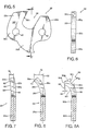
- Each cutter link is formed from a substantially planar steel plate blank as illustrated for cutter link 22 in Figs. 5 and 6.
- the blank includes a depending tang portion 22a, an intermediate portion 22b, an upwardly projecting cutter portion 22c, and an upwardly projecting depth gauge portion 22d spaced from cutter portion 22c by an open gullet region 38.
- cutter portion 22c extends above the elevation of depth gauge portion 22d.
- a pair of circular bores, or apertures, 40, 42 are defined adjacent opposite ends of the intermediate portion 22b.
- the cutter portion 22c has opposite side face surfaces 22f, 22g and a front face surface 22h which defines one side of gullet region 38.
- cutter portion 22c is bent over at an angle 44 to one side of the center plane 46 of the drive tang and intermediate portions of the cutter as seen in Figs. 3 and 7.
- the material from which the cutter is manufactured may be on the order of .042 inch thick.
- the cutter portion 22c may be bent outwardly at an angle 44 of about 10° from the center plane 46 of remainder portions of the blank.
- a similar blank is used to form cutters 26, however the upper cutter portion 26c is bent over at a greater angle 50 from the center plane 52 of remainder portions of the cutter than angle 44 which was formed in cutter 22.
- Angle 50 in the illustrated cutter may be on the order of 30°.
- Cutter portion 26c of cutter link 26 also has opposed side face surfaces 26f, 26g, and a front face surface 26h.
- a cutter link which may be used in place of cutter links 26 and 28 is illustrated. It includes a depending tang portion 90a, an intermediate portion 90b, and upwardly projecting cutter portion 90c. It would also have an upwardly projecting depth gauge portion spaced from the cutter portion by an open gullet region as illustrated for the other cutters, but which are not shown here for simplicity. Similarly, it would have a pair of circular bores 40, 42 adjacent opposite ends of intermediate portion 90b.
- the cutter portion 90c has opposite side face surfaces 90f, 90g and a front face surface 90h defining one side of the open gullet region.
- the cutter portion 90c is bent over at an angle somewhat greater than angle 50 to which the upper portion of cutter 26 is bent.
- the extreme upper region of portion 90c then is coined at opposite sides to produce an inward face 90j substantially parallel to the center plane 98 of remainder portions of the cutter and an outer face 90k which is formed at a slight angle 94 from a line 96 paralleling plane 98 of remainder portions of the cutter.
- This coined outer surface 90k will produce a leading side cutting edge which provides a kerf wall fiber shearing edge in the chain.
- Final forming of a cutter is produced by top grinding the upper surfaces of the cutter portions using a known top grinding procedure.
- the depth gauge may or may not be ground.
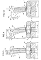
- the chain is sharpened after assembly and in so doing all the cutter portions are ground to substantially the same height. This is illustrated in Figs. 3, 4, 4A, 7, 8 and 8A where cutter 22 is ground along a horizontal line to form top surface 22e, cutter 26 is ground along a horizontal line to form top surface 26e, and cutter 90 is ground to form top surface 90e.
- top surface of 22e and front surface 22h define therebetween a top plate cutting edge 54.
- the convergence of front face 22h and side face 22f define a generally upright side cutting edge 56.
- the convergence of top surface 22e and side surface 22f define therebetween a top plate edge 58.
- the convergence of these three edges 54, 56, 58 define an outwardly projecting cutting point 60.
- the top plate cutting edge 54 is disposed at a substantial angle 67 relative to center line 65 of the chain. Angle 67 between center line 65 of the chain and the top plate cutting edge 54 is in a range of approximately 82° to 88°.
- cutters 26, 28 are formed by the same method as is used for cutters 22, 24, cutter 26 has a top plate cutting edge 64, a side plate cutting edge 66, and a top plate edge 68.
- a cutting point 70 is defined at the convergence of edges 64, 66, 68.
- the angle 74 between the top cutting edge 64 of cutters 26, 28 and center line 65 of the chain is in a range of 60° to 75°, which is less than the angle 67 for top plate cutting edge 54 for cutter links 22, 24.
- the cutter points 60 of cutters 22, 24 extend a distance 78 laterally of the center plane 46 of remainder portions of the link.
- Cutter points 70 of cutters 26, 28 extend a distance 79 from the center plane 52 of remainder portions of the link which is greater than distance 78.
- distance 78 is about .040 inch and 79 is about .100 inch. This provides a kerf-cutting width of about .200 inch.
- connector links 32, 34 each of these is formed from a length of round wire.
- a connector link 32 it includes an elongate central portion 32a, a pair of opposed end portions, 32b, 32c, and a pair of bight portions 32d, 32e.
- end portion 32c is bent up to overlie and protect underlying end portion 32b.
- ends 32f, 32g of the wire have been blunted so that there is little likelihood that they will catch in material to be cut which could impose unwanted stress on the connecting link, as occurs in prior art devices having sharpened ends to produce cutting.
- These two end portions may be secured together, as by welding for added strength.
- Bight portions 32d, 32e extend through bores 42, 40, respectively, in successive links in the chain.
- the side-to-side, or lateral, dimension 82 of a connector link is less than the lateral, side-to-side, dimension of cutting points 70 on cutter links 26, 28.
- dimension 82 is about .145 inch.
- point 70 projects a distance 81 beyond the outside of connector link 34, which in the illustrated embodiment is about .0275 inch.
- bores 40, 42 through which connector links 32, 34 extend are substantially larger in diameter than the diameter of the wire from which the connector links are constructed.
- bores 40, 42 have diameters of approximately .060 inch and the wire forming the connector links has a diameter of approximately .045 inch.
- the upright cutter links are positioned with their depending drive tang portions received in groove 16 in the guide bar.
- the connector links lie substantially horizontally with their undersides resting on the tops of guide rails 12, 14 of the guide bar.
- the chain is driven in the direction of arrow 80 about bar 10.
- the cutter links cut a kerf through material, such as wood, which is at least as wide as the lateral, or side-to-side, distance between points 70 on cutter links 26, 28, at opposite sides of the chain.
- the connector links, 32, 34 have a lesser side-to-side, or lateral, dimension than the kerf width and thus do not have substantial contact with material being cut. If they should, the fact that the ends of the wire from which the connector links are formed is blunted and the forwardly directed end of the wire connector is overlaid by a rearwardly directed end portion, there is little chance that snagging will occur which would tend to separate the loop. Thus, the connector links are not subjected to substantial forces that would tend to separate the links as in prior chain.
- the bight portion of the connector link generally moves to the portion of the bore most remote from the center of the cutter link. This tends to center the bight of the connector link relative to the top and bottom of the bore (i.e., as illustrated in solid outline in Fig. 1, the bight portions of the connector links are substantially centered vertically in bores 40, 42 in the cutter links).
- some vertical movement can occur between the wire connector link and its associated cutter link. This allows a cutter to rock rearwardly as indicated by the dashed outline configuration for cutter 24 in Fig. 1.
- the difference in vertical dimensions between the bore and connector is substantial enough that the angle 84 through which the cutter may rock may be in the range of from 2° to 10°.
- the cutter link when the cutter link enters the cut it is in the position illustrated in solid outline.
- the chain link On engaging the workpiece, such as a piece of wood, if the resistance to cut is too great, the chain link may rock rearwardly as indicated in dashed outline to reduce the depth gage setting and reduce the bite being taken by the cutter, thus to reduce forces imparted to the cutting system which produce vibration.
- the tension in the chain Upon release of the cutter from engagement with the wood, the tension in the chain will draw it back to the centered cutting position shown in solid outline.
- the built-in looseness of the chain parts provided by difference in size of the diameter of the wire in the connector links and the bores in the cutter links helps to reduce kinking that often occurs in saw chain. Also, it allows the chain to shorten, or accordian lengthwise, as it moves off the driving sprocket toward the guide bar groove. This reduces the possibility that the chain will be thrown from the bar during operation.
Landscapes
- Life Sciences & Earth Sciences (AREA)
- Engineering & Computer Science (AREA)
- Mechanical Engineering (AREA)
- Wood Science & Technology (AREA)
- Forests & Forestry (AREA)
- Sawing (AREA)
Applications Claiming Priority (2)
| Application Number | Priority Date | Filing Date | Title |
|---|---|---|---|
| US97587292A | 1992-11-13 | 1992-11-13 | |
| US975872 | 1992-11-13 |
Publications (2)
| Publication Number | Publication Date |
|---|---|
| EP0597816A2 true EP0597816A2 (fr) | 1994-05-18 |
| EP0597816A3 EP0597816A3 (en) | 1994-08-17 |
Family
ID=25523516
Family Applications (1)
| Application Number | Title | Priority Date | Filing Date |
|---|---|---|---|
| EP9393850214A Withdrawn EP0597816A3 (en) | 1992-11-13 | 1993-11-11 | Saw chain with wire form connectors. |
Country Status (2)
| Country | Link |
|---|---|
| EP (1) | EP0597816A3 (fr) |
| JP (1) | JPH06218701A (fr) |
Cited By (2)
| Publication number | Priority date | Publication date | Assignee | Title |
|---|---|---|---|---|
| WO2017027297A1 (fr) * | 2015-08-07 | 2017-02-16 | Peerless Chain Company | Chaîne d'écorçage possédant des maillons courbés |
| CN117621193A (zh) * | 2022-08-24 | 2024-03-01 | 米沃奇电动工具公司 | 链锯链 |
Family Cites Families (7)
| Publication number | Priority date | Publication date | Assignee | Title |
|---|---|---|---|---|
| DE651063C (de) * | 1935-09-21 | 1937-10-07 | Stihl Andreas | Leicht loesbares Kettenschloss, insbesondere fuer Saegeketten, dessen Schlossbolzen mit Rillen versehen ist |
| US2351738A (en) * | 1941-08-22 | 1944-06-20 | Arthur N Blum | Cutting chain |
| FR1004489A (fr) * | 1947-04-29 | 1952-03-31 | Outil à éléments multiples sans axe ni charnière pour le havage et le sciage des roches | |
| DE931548C (de) * | 1948-11-17 | 1955-08-11 | Hans Wyss | Kettensaegeband |
| CH268249A (de) * | 1948-11-17 | 1950-05-15 | Wyss Hans | Kettensägeband. |
| US2608222A (en) * | 1949-02-01 | 1952-08-26 | Ivar N Jensen | Saw chain |
| US4827821A (en) * | 1986-11-10 | 1989-05-09 | Omark Industries, Inc. | Cutting chain |
-
1993
- 1993-11-11 EP EP9393850214A patent/EP0597816A3/en not_active Withdrawn
- 1993-11-12 JP JP28349393A patent/JPH06218701A/ja active Pending
Cited By (4)
| Publication number | Priority date | Publication date | Assignee | Title |
|---|---|---|---|---|
| WO2017027297A1 (fr) * | 2015-08-07 | 2017-02-16 | Peerless Chain Company | Chaîne d'écorçage possédant des maillons courbés |
| US10688682B2 (en) | 2015-08-07 | 2020-06-23 | Peerless Chain Company | Debarking chain having bent links |
| AU2016306213B2 (en) * | 2015-08-07 | 2021-02-25 | Peerless Chain Company | Debarking chain having bent links |
| CN117621193A (zh) * | 2022-08-24 | 2024-03-01 | 米沃奇电动工具公司 | 链锯链 |
Also Published As
| Publication number | Publication date |
|---|---|
| JPH06218701A (ja) | 1994-08-09 |
| EP0597816A3 (en) | 1994-08-17 |
Similar Documents
| Publication | Publication Date | Title |
|---|---|---|
| EP0865886B1 (fr) | Limiteur de coupe | |
| EP1370399B1 (fr) | Scie a chaine a affutage automatique | |
| CA1306405C (fr) | Maillon a elements de liaison rabattus | |
| US4425830A (en) | Anti-kickback saw chain | |
| JP3486026B2 (ja) | 無終端カッター装置用カッター | |
| US2583243A (en) | Chain saw | |
| US5029501A (en) | Roughing cutter for saw chain | |
| US3745870A (en) | Saw chain | |
| US4535667A (en) | Saw chain | |
| US20240066744A1 (en) | Chainsaw chains | |
| EP0597816A2 (fr) | Chaîne de sciage à éléments de liaison sous forme de fil | |
| US5092211A (en) | Saw chain having cutter link with central pivot on bottom edge | |
| US4898057A (en) | Low vibration center drive cutter chain | |
| US4562762A (en) | Low kick saw chain | |
| US5172619A (en) | Single side cutter tooth with facing raker tooth | |
| US2873775A (en) | Saw chains | |
| US3613749A (en) | Saw chain with dual cutters | |
| US4841825A (en) | Saw chain with wrap-over depth gauge | |
| EP0268054B1 (fr) | Chaîne coupante | |
| US4203215A (en) | Endless chain for a chain saw | |
| US4426900A (en) | Saw chain using an improved side cutter tooth | |
| US4796502A (en) | Saw blade structure with depth-control means | |
| US3748942A (en) | Stabilizing center drive link for saw chain | |
| US3989076A (en) | Pulp chip forming crosscut saws | |
| CN217826054U (zh) | 单向防反弹手拉链 |
Legal Events
| Date | Code | Title | Description |
|---|---|---|---|
| PUAI | Public reference made under article 153(3) epc to a published international application that has entered the european phase |
Free format text: ORIGINAL CODE: 0009012 |
|
| AK | Designated contracting states |
Kind code of ref document: A2 Designated state(s): DE FR GB |
|
| PUAL | Search report despatched |
Free format text: ORIGINAL CODE: 0009013 |
|
| AK | Designated contracting states |
Kind code of ref document: A3 Designated state(s): DE FR GB |
|
| STAA | Information on the status of an ep patent application or granted ep patent |
Free format text: STATUS: THE APPLICATION IS DEEMED TO BE WITHDRAWN |
|
| 18D | Application deemed to be withdrawn |
Effective date: 19950218 |