EP0597897B1 - Einrichtung zur versorgung einer nichtlinearen last - Google Patents
Einrichtung zur versorgung einer nichtlinearen last Download PDFInfo
- Publication number
- EP0597897B1 EP0597897B1 EP92915711A EP92915711A EP0597897B1 EP 0597897 B1 EP0597897 B1 EP 0597897B1 EP 92915711 A EP92915711 A EP 92915711A EP 92915711 A EP92915711 A EP 92915711A EP 0597897 B1 EP0597897 B1 EP 0597897B1
- Authority
- EP
- European Patent Office
- Prior art keywords
- voltage
- current
- supply line
- power supply
- intensity
- Prior art date
- Legal status (The legal status is an assumption and is not a legal conclusion. Google has not performed a legal analysis and makes no representation as to the accuracy of the status listed.)
- Expired - Lifetime
Links
- 238000004804 winding Methods 0.000 claims abstract description 17
- 230000010355 oscillation Effects 0.000 claims abstract description 4
- 238000012935 Averaging Methods 0.000 claims description 4
- 238000005070 sampling Methods 0.000 claims description 3
- 238000005259 measurement Methods 0.000 description 7
- 239000003990 capacitor Substances 0.000 description 6
- 230000004913 activation Effects 0.000 description 2
- 238000010438 heat treatment Methods 0.000 description 2
- 230000001629 suppression Effects 0.000 description 2
- 230000003247 decreasing effect Effects 0.000 description 1
- 238000011144 upstream manufacturing Methods 0.000 description 1
Images

Classifications
-
- H—ELECTRICITY
- H05—ELECTRIC TECHNIQUES NOT OTHERWISE PROVIDED FOR
- H05B—ELECTRIC HEATING; ELECTRIC LIGHT SOURCES NOT OTHERWISE PROVIDED FOR; CIRCUIT ARRANGEMENTS FOR ELECTRIC LIGHT SOURCES, IN GENERAL
- H05B6/00—Heating by electric, magnetic or electromagnetic fields
- H05B6/64—Heating using microwaves
- H05B6/66—Circuits
- H05B6/666—Safety circuits
Definitions
- the invention relates to a device for supplying a non-linear load which is connected to an alternating current distribution network.
- the supply device comprises a rectifier connected to the terminals of said network and formed by a full-wave diode bridge, the output of which is connected by two supply lines to the primary winding of a high voltage transformer, the secondary winding being connected by two supply lines to the non-linear load, a high frequency interference suppression filter positioned at the output of said rectifier and consisting of an inductor and a capacitor, a high frequency switching element positioned on one supply lines and having a trigger connected to a control circuit and a device for measuring the intensity of the current flowing in the supply line containing the switching element.
- Said intensity measurement device makes it possible to detect a value of current flowing in the supply line containing said switching element.
- the value thus detected is sent to the control circuit which applies trigger signals to the trigger of the switching element.
- the trigger signals sent to the control circuit make the switching element conductive by authorizing the passage of current from the other supply line connected to the primary winding to the supply line containing the switching element.
- the average intensity delivered at each pulse being a function of the switch control frequency, said control frequency can be controlled by the measured value of said average intensity so that the latter remains constant.
- a device corresponding to the preamble of claim 1 is for example known from document EP-A-0 289 032.
- the object of the invention is to remedy these drawbacks by implementing an intensity measurement device correcting the frequency of the triggering signals of the control circuit.
- the measurement device comprises a sensor intended to take the intensity on the supply line and associated with a storage device which makes it possible to store a voltage proportional to the intensity passing through the switching element averaged over a period of the high frequency oscillation, a device for squaring the rectified mains voltage
- the intensity of the current in the supply line is measured at each opening of the switching element, this calculation making it possible to take into account all the variations in the average intensity of the pulses.
- the frequency of the trigger signal is corrected either increasing or decreasing, thereby acting on the power supplied to the non-linear load.
- the power absorbed by the load can therefore be adjusted at each switching and, therefore, the absorbed intensity can be kept close to a sinusoidal shape and said absorbed power controlled by a set value.
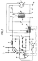
- FIG. 1 represents an example of mounting of a device for measuring intensity according to the invention and positioned in a supply circuit of a magnetron
- FIG. 2 represents a circuit of a device for measuring the intensity of a non-linear load adapted to be mounted in the circuit of FIG. 1.
- the circuit is intended more particularly for supplying a non-linear load such as a magnetron 1 of a microwave oven from an alternative distribution network arriving at terminals 3 and 4 of the circuit.
- These terminals 3 and 4 are connected to a rectifier 5 which is formed by a full-wave diode bridge and the output of which is connected to two lines 6 and 7 supplying a high voltage transformer 8.
- a filter high frequency interference suppression is positioned at the output of said rectifier 5 and consists of a self-inductance 9 and a capacitor 10.
- the lines 6 and 7 are connected respectively to the ends 11 and 12 of the primary winding 13 of the transformer 8.
- the supply line 7 also includes a switching element 14 having a trigger 15 connected to a control circuit 16 as well as a switching aid device 16 ′.
- Said switching element 14 is constituted by a unidirectional current switch.
- the unidirectional switch 14 is connected, for example, in series with a diode 20 preventing reverse current to the source, thus ensuring a better ratio: average current injected on effective current in the primary circuit.
- the diode 20 can be mounted in parallel with the unidirectional switch 14.
- the circuit also includes a capacitor 18 connected in parallel to said winding 13, as well as a self-inductance 17 connected in series with the assembly thus constituted by the capacitor 18 and the primary winding 13.
- the inductor 17 is coupled to a secondary winding 21 the ends of which are connected to the heating element 20 of the magnetron 1.
- the secondary winding 19 of said transformer 8 comprises respectively two terminals 21 and 22 connected respectively to two supply lines 23 and 24 connected one 23 to the cathode 2 of magnetron 1 and the other 24, to the anode 25 of said magnetron which is also connected to ground 26.
- the frequency of the trigger signals varies according to the value of the current flowing in the supply line 7.
- the value of said current is analyzed by an intensity measurement device 28.
- the measurement device 28 comprises a sensor 30 intended to take the intensity from the supply line 7 and associated with a storage device 34 which makes it possible to memorize a voltage proportional to the intensity passing through the switching element 14 averaged over a period of the high frequency oscillation, a device 43 for raising the mains voltage squared straightened
- the sensor 30 comprises a winding, for example, that of a high frequency intensity transformer 29.
- the winding 30 has two terminals 31 and 32, one of which 32 is connected to ground.
- a resistor R1 is connected in parallel to the winding 30 at the terminals 31 and 32.
- the terminal 31 is connected to one of the inputs 33 of the storage device 34 constituted, for example, by a sample-and-hold amplifier controlled by the activation of 'a clock clk has on an input 35.
- the activation of the clock clk has controls a switching device not shown forming an integral part of the amplifier 34 which triggers the measurement of the value of the intensity of the line of power supply 7 by memorizing it at a so-called sampling instant.
- This selected sampling instant corresponds to the instant when the switch 14 is open and where the current in lines 6 and 7 is zero, the voltage stored at said instant then being equal to the average value of the current in the switch 14 with the time constant of the high frequency intensity transformer 29.
- the senor 30 is constituted by a winding 31 carried out on the magnetic circuit of the self-inductance 17 charged by an integrator circuit with resistance R and capacitor C.
- the senor 30 is constituted by a high-pass filter associated with an RC integrator circuit connected directly to the terminals of the self inductance 17.
- the measuring device 28 is connected by a line 28A to the supply line 6, for example, upstream of the capacitor 18 connected in parallel with the primary winding 13, and this line 28A takes the mains voltage straightened
- the second input 44 of the multiplier 41 receives the reference power Po of the non-linear load at start-up, this value being corrected during operation.
- the output S1 of said multiplier 41 is connected to a first input 45 of the error amplifier 46.
- the output 47 of the square elevation device 43 is connected to an input 48 of the first multiplier 38.
- the output S2 of said multiplier 38 is connected to a second input 49 of the error amplifier 46.
- the output 50 of the error amplifier 46 is connected to an input 51 of the control circuit 16.
- the measuring device intensity according to the invention operates in the manner described below.
- the sample-and-hold amplifier 34 thus makes it possible to store the value of the current flowing on the supply line 7.
- the amplifier 34 delivers, at a determined instant, the corresponding value I to a multiplier 38 which makes it possible to carry out the product of said intensity by the absolute value of the square of the rectified mains voltage
- the multiplier 41 performs the product of the absolute value of the rectified mains voltage
- taken from the supply line 6 by the reference power P0 of the load and delivers, on its output S1, the product P2
- This product P2 is sent to the input 42 of the error amplifier 46.
- the amplifier 46 compares the input signals 42 and 49, that is to say if in equilibrium condition we have
- . P0 ⁇
- the output signal 50 of said error amplifier 46 is sent to the input 51 of the control circuit 16 which controls the switching element 14, so that the enslavement of the resulting switching frequency ensures both a variation in the intensity taken from the sector proportional to the voltage delivered by said sector and a power consumption equal to the set power P0.
Landscapes
- Physics & Mathematics (AREA)
- Electromagnetism (AREA)
- Dc-Dc Converters (AREA)
- Control Of High-Frequency Heating Circuits (AREA)
- Measurement Of Current Or Voltage (AREA)
Claims (7)
- Versorgungsvorrichtung für eine nichtlineare Last, die an ein Wechselstromverteilernetz angeschlossen ist und einen mit den Anschlüssen (3 und 4) des Netzes verbundenen Gleichrichter (5), dessen Ausgang über zwei Versorgungsleitungen (6 und 7) an die Primärwicklung (13) eines Hochspannungstransformators (8) angeschlossen ist, wobei die Sekundärwicklung (19) über zwei Versorgungsleitungen (23 und 24) mit der nichtlinearen Last (1) verbunden ist, ein Hochfrequenzumschaltelement (14), das an der Versorgungsleitung (7) positioniert ist und ein mit einer Steuerschaltung (16) verbundenes Gate (15) umfaßt, sowie eine Meßeinrichtung (28) für die Stärke des in der Versorgungsleitung (7) fließenden Stroms mit einem Sensor (30) aufweist, der dazu bestimmt ist, die Stärke an der Versorgungsleitung (7) abzunehmen und einer Speichereinrichtung (34) zugeordnet ist, die die Speicherung einer Spannung ermöglicht, die zu der das Umschaltelement (14) durchquerenden Stärke proportional ist, gemittelt über eine Hochfrequenzschwingungsperiode,
dadurch gekennzeichnet, daß die Meßeinrichtung (28) ferner eine Einrichtung (43) zur Quadrierung der gleichgerichteten Sektorspannung |u| aufweist, die an der Versorgungsleitung (6) erfaßt wird, sowie zum Mitteln des erhaltenen Wertes an der Periode des Sektors, einen ersten Multiplizierer (38), der das Produkt des letzten Mittelwerts mit dem Wert der von der Speichereinrichtung (34) gespeicherten Spannung erstellt, einen zweiten Multiplizierer (41), der das Produkt der gleichgerichteten Sektorspannung |u| mit der Einstelleistung P₀ erstellt, sowie einen Fehlerverstärker (46), dessen Eingänge (45-49) mit den Ausgängen (S₁, S₂) der Multiplizierer (38-41) verbunden sind und dessen Ausgangssignal die Steuerschaltung (16) für das Umschaltelement (14) derart steuert, daß die sich daraus ergebende Regelung der Umschaltfrequenz gleichzeitig eine Änderung der an dem Sektor abgenommenen Stärke proportional zu der von dem Sektor abgegebenen Spannung und einen Leistungsverbrauch gewährleistet, die gleich der Einstelleistung P₀ ist. - Versorgungsvorrichtung nach Anspruch 1,
dadurch gekennzeichnet, daß der die Stärke in der Versorgungsleitung (7) abnehmende Sensor (30) ein Hochfrequenzstromwandler (29) ist. - Versorgungsvorrichtung nach Anspruch 2,
dadurch gekennzeichnet, daß die Speichervorrichtung ein Abtast- und Halteverstärker ist, der mit den Anschlüssen des Wandlers (29) verbunden ist, und dessen gewählter Abtastzeitpunkt dem Zeitpunkt entspricht, zu dem der Schalter (14) geöffnet ist und der Strom in den Leitungen (6 und 7) null ist, wobei die zu dem Zeitpunkt gespeicherte Spannung dann gleich dem Mittelwert des Stroms in dem Schalter (14) mit der Zeitkonstante des Hochfrequenzstromwandlers (29) ist. - Versorgungsvorrichtung nach Anspruch 3,
dadurch gekennzeichnet, daß der Abtast- und Halteverstärker (34) einen Ausgang (36) aufweist, der mit einem Eingang (37) des ersten Multiplizierers (38) verbunden ist, der seinerseits über einen Eingang (48) mit der Einrichtung (43) zur Quadrierung und Mittelung verbunden ist und von dem ein Ausgang (52) mit einem (49) der Eingänge des Fehlerverstärkers (46) verbunden ist, wobei der andere (45) der Eingänge des Fehlerverstärkers an den Ausgang des zweiten Multiplizierers (41) angeschlossen ist, von dem ein Eingang (44) die Einstelleistung P₀ erhält und ein anderer Eingang (40) mit der Versorgungsleitung (6) verbunden ist, die ihrerseits mit dem Eingang (42) der Einrichtung (43) verbunden ist. - Versorgungsvorrichtung nach Anspruch 1, die ferner eine mit der Umschalteinrichtung (14) in Reihe geschaltete Selbstinduktionsspule (17) aufweist,
dadurch gekennzeichnet, daß der Sensor (30) durch eine Wicklung (31) gebildet ist, die an dem Magnetkreis der Selbstinduktionsspule (17) ausgeführt ist, die durch eine Integratorschaltung (32) belastet ist. - Versorgungsvorrichtung nach Anspruch 1, die ferner eine mit der Umschalteinrichtung (14) in Reihe geschaltete Selbstinduktionsspule (17) aufweist,
dadurch gekennzeichnet, daß der Sensor (30) durch ein Hochpaßfilter gebildet ist, das einer Integratorschaltung zugeordnet ist, die mit den Anschlüssen der Selbstinduktionsspule (17) verbunden ist. - Versorgungsvorrichtung nach einem der vorhergehenden Ansprüche,
dadurch gekennzeichnet, daß die nichtlineare Last ein Magnetron ist.
Applications Claiming Priority (3)
| Application Number | Priority Date | Filing Date | Title |
|---|---|---|---|
| FR9110176A FR2680297B1 (fr) | 1991-08-09 | 1991-08-09 | Dispositif d'alimentation d'une charge non lineaire. |
| FR9110176 | 1991-08-09 | ||
| PCT/FR1992/000656 WO1993003587A1 (fr) | 1991-08-09 | 1992-07-08 | Dispositif d'alimentation d'une charge non lineaire |
Publications (2)
| Publication Number | Publication Date |
|---|---|
| EP0597897A1 EP0597897A1 (de) | 1994-05-25 |
| EP0597897B1 true EP0597897B1 (de) | 1995-02-15 |
Family
ID=9416095
Family Applications (1)
| Application Number | Title | Priority Date | Filing Date |
|---|---|---|---|
| EP92915711A Expired - Lifetime EP0597897B1 (de) | 1991-08-09 | 1992-07-08 | Einrichtung zur versorgung einer nichtlinearen last |
Country Status (4)
| Country | Link |
|---|---|
| EP (1) | EP0597897B1 (de) |
| DE (1) | DE69201445T2 (de) |
| FR (1) | FR2680297B1 (de) |
| WO (1) | WO1993003587A1 (de) |
Families Citing this family (3)
| Publication number | Priority date | Publication date | Assignee | Title |
|---|---|---|---|---|
| FR2772208B1 (fr) * | 1997-12-05 | 2000-02-25 | Sgs Thomson Microelectronics | Dispositif d'alimentation d'une charge non lineaire, notamment un magnetron d'un four a micro-ondes |
| KR100591314B1 (ko) | 2003-12-05 | 2006-06-19 | 엘지전자 주식회사 | 인버터 전자레인지 및 그 제어방법 |
| US7696458B2 (en) | 2005-06-03 | 2010-04-13 | Illinois Tool Works Inc. | Induction heating system and method of output power control |
Family Cites Families (4)
| Publication number | Priority date | Publication date | Assignee | Title |
|---|---|---|---|---|
| DE3625011A1 (de) * | 1985-11-08 | 1987-05-21 | Aeg Elotherm Gmbh | Einrichtung zur messung der wirkleistung in einem als schwingkreis ausgebildeten lastkreis eines statischen elektrischen umrichters |
| AU592262B2 (en) * | 1987-04-30 | 1990-01-04 | Matsushita Electric Industrial Co., Ltd. | Magnetron feeding apparatus and method of controlling the same |
| DE3731555C1 (en) * | 1987-09-19 | 1988-12-15 | Aeg Elotherm Gmbh | Induction heating device with a setting preset controlled by the actual value |
| SE462253B (sv) * | 1988-10-14 | 1990-05-21 | Philips Norden Ab | Matningsanordning i en mikrovaagsugn samt anvaendning av anordningen |
-
1991
- 1991-08-09 FR FR9110176A patent/FR2680297B1/fr not_active Expired - Fee Related
-
1992
- 1992-07-08 DE DE69201445T patent/DE69201445T2/de not_active Expired - Fee Related
- 1992-07-08 WO PCT/FR1992/000656 patent/WO1993003587A1/fr not_active Ceased
- 1992-07-08 EP EP92915711A patent/EP0597897B1/de not_active Expired - Lifetime
Also Published As
| Publication number | Publication date |
|---|---|
| EP0597897A1 (de) | 1994-05-25 |
| WO1993003587A1 (fr) | 1993-02-18 |
| FR2680297A1 (fr) | 1993-02-12 |
| DE69201445D1 (de) | 1995-03-23 |
| FR2680297B1 (fr) | 1996-10-25 |
| DE69201445T2 (de) | 1995-06-29 |
Similar Documents
| Publication | Publication Date | Title |
|---|---|---|
| EP0593660B1 (de) | Einrichtung zum Detektieren der Dysfunktion eines Verbrauchers wie ein Magnetron | |
| FR2745446A1 (fr) | Circuit integre de correction de facteur de puissance | |
| JPH07336910A (ja) | 太陽電池発電電力の蓄電装置 | |
| FR2483625A1 (fr) | Compteur electronique d'energie electrique | |
| WO2002035693A1 (fr) | Convertisseur de tension a circuit de commande autooscillant | |
| FR2766304A1 (fr) | Circuit d'alimentation pour un compteur d'electricite | |
| EP0597897B1 (de) | Einrichtung zur versorgung einer nichtlinearen last | |
| FR2718318A1 (fr) | Dispositif de commande et de contrôle automatiques de puissance pour un appareil de chauffage par induction et procédé de mise en Óoeuvre de ce dispositif. | |
| FR2614431A1 (fr) | Circuit de traitement d'un signal pseudo-oscillatoire, notamment pour detecteur de proximite inductif | |
| FR2685474A1 (fr) | Circuit d'exploitation pour capteur inductif dont l'inductance depend de la grandeur a mesurer. | |
| EP1383222A1 (de) | Batterielader | |
| EP0544589B1 (de) | Gerät zur Messung des realen Lastfaktors eines elektrischen Generators | |
| FR2489197A1 (fr) | Circuit de surveillance pour appareil de soudage electrique | |
| EP0471625B1 (de) | Vorrichtung zur Erzeugung einer regelbaren Gleichspannung | |
| FR2563956A1 (fr) | Circuit integrable pour l'echantillonnage de la tension d'une charge | |
| EP0457649A1 (de) | Momentan-Leistungsmesschaltung | |
| FR3075968A1 (fr) | Circuit de recherche du point de puissance maximum | |
| EP0030497B1 (de) | Schaltung zur Bestimmung des durch einen elektrischen Asynchronmotor gelieferten Kräftepaars | |
| FR2765000A1 (fr) | Procede pour compenser un regulateur d'intensite | |
| KR20000073180A (ko) | 입력전압의 히스테리시스를 이용한 역률 보상 제어장치 | |
| FR3007843A1 (fr) | Procede et dispositif de determination de la phase d’un signal alternatif | |
| EP0042344B1 (de) | Vorrichtung zur Temperaturregelung | |
| BE853124A (fr) | Dispositif de regulation du courant delivre a une charge a partir de plusieurs sources d'energie | |
| EP0603051B1 (de) | Gleichstromzerhackersteuerschaltung | |
| FR2526244A1 (fr) | Circuit stabilise d'alimentation en courant alternatif du type a commande de phase |
Legal Events
| Date | Code | Title | Description |
|---|---|---|---|
| PUAI | Public reference made under article 153(3) epc to a published international application that has entered the european phase |
Free format text: ORIGINAL CODE: 0009012 |
|
| 17P | Request for examination filed |
Effective date: 19940125 |
|
| AK | Designated contracting states |
Kind code of ref document: A1 Designated state(s): DE GB NL SE |
|
| 17Q | First examination report despatched |
Effective date: 19940624 |
|
| GRAA | (expected) grant |
Free format text: ORIGINAL CODE: 0009210 |
|
| AK | Designated contracting states |
Kind code of ref document: B1 Designated state(s): DE GB NL SE |
|
| REF | Corresponds to: |
Ref document number: 69201445 Country of ref document: DE Date of ref document: 19950323 |
|
| GBT | Gb: translation of ep patent filed (gb section 77(6)(a)/1977) |
Effective date: 19950313 |
|
| PLBE | No opposition filed within time limit |
Free format text: ORIGINAL CODE: 0009261 |
|
| STAA | Information on the status of an ep patent application or granted ep patent |
Free format text: STATUS: NO OPPOSITION FILED WITHIN TIME LIMIT |
|
| 26N | No opposition filed | ||
| REG | Reference to a national code |
Ref country code: GB Ref legal event code: IF02 |
|
| PGFP | Annual fee paid to national office [announced via postgrant information from national office to epo] |
Ref country code: SE Payment date: 20020531 Year of fee payment: 11 |
|
| PGFP | Annual fee paid to national office [announced via postgrant information from national office to epo] |
Ref country code: GB Payment date: 20020701 Year of fee payment: 11 |
|
| PGFP | Annual fee paid to national office [announced via postgrant information from national office to epo] |
Ref country code: DE Payment date: 20020705 Year of fee payment: 11 |
|
| PGFP | Annual fee paid to national office [announced via postgrant information from national office to epo] |
Ref country code: NL Payment date: 20020731 Year of fee payment: 11 |
|
| PG25 | Lapsed in a contracting state [announced via postgrant information from national office to epo] |
Ref country code: GB Free format text: LAPSE BECAUSE OF NON-PAYMENT OF DUE FEES Effective date: 20030708 |
|
| PG25 | Lapsed in a contracting state [announced via postgrant information from national office to epo] |
Ref country code: SE Free format text: LAPSE BECAUSE OF NON-PAYMENT OF DUE FEES Effective date: 20030709 |
|
| NLS | Nl: assignments of ep-patents |
Owner name: SEB S.A. |
|
| PG25 | Lapsed in a contracting state [announced via postgrant information from national office to epo] |
Ref country code: NL Free format text: LAPSE BECAUSE OF NON-PAYMENT OF DUE FEES Effective date: 20040201 |
|
| PG25 | Lapsed in a contracting state [announced via postgrant information from national office to epo] |
Ref country code: DE Free format text: LAPSE BECAUSE OF NON-PAYMENT OF DUE FEES Effective date: 20040203 |
|
| GBPC | Gb: european patent ceased through non-payment of renewal fee |
Effective date: 20030708 |
|
| EUG | Se: european patent has lapsed | ||
| NLV4 | Nl: lapsed or anulled due to non-payment of the annual fee |
Effective date: 20040201 |