EP0597941B1 - Elektrisches kochgerät und verfahren zur herstellung desselben - Google Patents
Elektrisches kochgerät und verfahren zur herstellung desselben Download PDFInfo
- Publication number
- EP0597941B1 EP0597941B1 EP92916488A EP92916488A EP0597941B1 EP 0597941 B1 EP0597941 B1 EP 0597941B1 EP 92916488 A EP92916488 A EP 92916488A EP 92916488 A EP92916488 A EP 92916488A EP 0597941 B1 EP0597941 B1 EP 0597941B1
- Authority
- EP
- European Patent Office
- Prior art keywords
- pan
- casing
- top edge
- cooking appliance
- electrical cooking
- Prior art date
- Legal status (The legal status is an assumption and is not a legal conclusion. Google has not performed a legal analysis and makes no representation as to the accuracy of the status listed.)
- Expired - Lifetime
Links
Images

Classifications
-
- A—HUMAN NECESSITIES
- A47—FURNITURE; DOMESTIC ARTICLES OR APPLIANCES; COFFEE MILLS; SPICE MILLS; SUCTION CLEANERS IN GENERAL
- A47J—KITCHEN EQUIPMENT; COFFEE MILLS; SPICE MILLS; APPARATUS FOR MAKING BEVERAGES
- A47J37/00—Baking; Roasting; Grilling; Frying
- A47J37/12—Deep fat fryers, e.g. for frying fish or chips
- A47J37/1204—Deep fat fryers, e.g. for frying fish or chips for domestic use
- A47J37/1209—Deep fat fryers, e.g. for frying fish or chips for domestic use electrically heated
-
- A—HUMAN NECESSITIES
- A47—FURNITURE; DOMESTIC ARTICLES OR APPLIANCES; COFFEE MILLS; SPICE MILLS; SUCTION CLEANERS IN GENERAL
- A47J—KITCHEN EQUIPMENT; COFFEE MILLS; SPICE MILLS; APPARATUS FOR MAKING BEVERAGES
- A47J36/00—Parts, details or accessories of cooking-vessels
- A47J36/16—Inserts
Definitions
- the invention relates to electric cooking appliances, such as for example fryers, comprising a housing made of a plastic material capable of degrading at a high temperature and which surrounds, by providing a certain space, a metal tank heated by a heating means.
- the invention relates more precisely to cooking appliances in which the vessel rests on a series of supports made of heat-resistant material which are interposed between the upper edge of the housing and the upper edge of the vessel, and which thus leave between them spaces between said upper edges of the tank and of the housing so as to allow air circulation around the tank between openings made in the lower part of the housing and said spaces.
- the object of the invention is in particular to simplify the construction of such a cooking appliance.
- said supports each comprise one or more heads which are mounted integral with the upper edge of the tank before mounting the tank in the housing, and a body intended to come into engagement with the upper edge of the housing and comprising a member fixing with said edge of the housing.
- the supports being fixed directly on the edge of the tank, make it possible to simplify the subsequent operations of nesting and fixing of the tank in the housing, which makes possible a fully automated mass production.
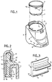
- the electric cooking appliance shown in FIG. 1 is a fryer which comprises a metal tank 1, the bottom of which is heated by a heating means 2 such as an armored electrical resistance, a housing 3 made of a plastic material capable of degrade at a high temperature such as, for example, that recorded on the upper edge 4 of the tank 1 which is of the order of 180 ° C.
- a heating means 2 such as an armored electrical resistance
- a housing 3 made of a plastic material capable of degrade at a high temperature such as, for example, that recorded on the upper edge 4 of the tank 1 which is of the order of 180 ° C.
- plastics are known, for example, under the name of ABS or Polypropylene.
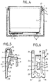
- said tank 1 rests inside the housing 3 on a series of supports 5 which are interposed between said upper edge 6 and the upper edge 4 of the tank, and which thus leave between them spaces 7 (see FIG. 4) between said upper edges so as to allow air circulation (arrows F in FIGS. 1 and 4) around the tank between said spaces and opening
- This circulation of air makes it possible in particular to obtain, not only, good ventilation of the space guaranteeing a more faithful operation of the thermostat generally fixed on the bottom of the tank and also preventing the stagnation of drops of oil which have interfered in this space between the supports and therefore the emanation of burnt, but also, a better distribution of the temperature of the tank heated by its bottom and therefore a better homogenization of the temperature of the oil bath.
- said supports 5 each comprise a head 9 which is mounted integral with the upper edge 4 of the tank 1 and a body 10 intended to come into engagement with the upper edge 6 of the housing and comprising a fixing member 11 with said edge 6.
- the top edge 4 of the tank 1 has a rim 12 folded downwards and outwards and defining a housing for the heads 9 of the supports 5, and the upper edge 6 of the housing has a horizontal border 13 directed inwards and followed by a descending rim 14 whose lower end 16 constitutes a notch.
- the supports 5 are four in number and each consist of a molded material such as a plastic material resistant over time to the temperature of the upper edge 4 of the tank, such as for example, of the polyamide or polyester type.
- Each support 5 has a generally t-shaped section, the upper end of the vertical branch of which forms the head 9 and the lower end of which carries the fixing member 11 which is formed by a hook directed towards the internal wall. of the housing 3, while the horizontal branch 15 of the "t" constitutes a support means intended to engage on the edge 13 of the housing.
- the heads 9 of the supports 5 are crimped into the housing of the edge of the tank.
- This crimping operation is illustrated schematically in Figure 2 in which is shown in broken lines 12 'the flange 12 before folding and in solid line the folded flange after crimping.
- a first operation is carried out consisting in mounting the supports 5 on the edge of the tank 4 by placing the heads 9 in the housing on the edge of the tank (position in dashed lines 12 ′), then a second operation consisting in crimping the heads 9 in this housing (edge of the tank 12 position in solid line), and finally a third operation in which the assembly is introduced from above. consisting of support vessels in the opening of the housing 3 until the horizontal branches 15 rest on the edge 13 and obtain engagement elastic hooks 11 on the lower end 16 of the rim 14.
- each fixing member 11 has a bevel 17 as well as a heel 18 which is applied against the wall of the tank 1.
- the elastic engagement is obtained by elastic deformation of the rim 14 of the housing 3, but it could, of course, be obtained, for example, by an elasticity at the level of the fixing member 11, in particular by eliminating the heel 18.
- the supports 5 can be replaced by supports of metal resistant to the temperature of the edge of the tank, for example of stainless steel and of different shape.
- Each metal support thus has the form of an oblong plate comprising, at one end, for example, at least one rolled edge forming a head and, in the body, a tongue forming a support means as well as a tab situated under the tongue and whose free end forms a hook.
- the oblong plate constituting a support 20 has two longitudinal notches 21 and 22 thus providing a body 23 in three tongues attached to a common base 23, namely two external tongues 24 whose free ends 25 have respectively a rolled edge forming a head, and whose lower ends form respectively a heel 26, as well as a central tongue 27 whose free end 28 is folded and forms the support means, and whose central region has a partial cutout 29 forming a tab 30 folded out of the plane of said tongue 27 and whose free end 31 constitutes a hook-shaped fixing member.
- each support 20 is crimped into the housing of the upper edge 4 of the tank 1 and the heels 26 bear on the external wall of the tank 1.
- the supports 5 are replaced by supports 33 made of metal wire, for example, stainless steel and has in front view ( Figure 8), a body 34 of generally "W", the two external sections 35 of which respectively have two free ends 36 shaped in a loop so as to form heads and the internal sections 37 of which, respectively connected by an elbow 38 to the two sections 35 each have a fold 39 constituting the fixing in the form of a hook, while the upper middle part of the two sections 37 conforms to a strip extending transversely to the sections 35 and 37 and constituting a support means 40.
- the manufacture of a fryer equipped with such supports (5-20-33) is particularly easy, well suited to automated mass production and particularly economical.
- the invention can be applied to other cooking appliances such as for example: rice cookers, electric pans, simmers, etc.
- the tank 1 is mounted free relative to to the housing 3 and does not need any other fixing member to hold it in this housing, which lowers the manufacturing price.
Landscapes
- Engineering & Computer Science (AREA)
- Food Science & Technology (AREA)
- Frying-Pans Or Fryers (AREA)
- Cookers (AREA)
Claims (10)
- Elektrisches Kochgerät, wie z.B. eine Friteuse, mit einem Gehäuse (3), das aus einem Kunststoffmaterial das erst bei hohen Temperaturen beschädigt wird, hergestellt ist, und das einen durch eine Heizvorrichtung (2) heizbaren Metalltopf (1) so umgibt, daß zwischen beiden ein gewisser Raum freibleibt, wobei der Topf auf mehreren Stützen (5-20-33) aus hitzebeständigem Material aufliegt, die zwischen dem oberen Rand (6) des Gehäuses (3) und dem oberen Rand (4) des Topfes (1) angebracht sind und die so zwischen sich Öffnungen (7) zwischen dem oberen Rand des Topfes und dem oberen Rand des Gehäuses lassen, so daß Luft zwischen Öffnungen (8), die im unteren Teil des Gehäuses ausgebildet sind, und den Öffnungen (7) rings um den Topf zirkulieren kann, dadurch gekennzeichnet, daß die Stützen (5-20-33) jede einen oder mehrere Köpfe (9-25-36), die vor dem Einbau des Topfes in das Gehäuse am oberen Rand (4) des Topfes (1) fest gehalten sind, und einen Körper (10-23-34) aufweisen, der mit dem oberen Rand (6) des Gehäuses (3) in Eingriff kommen soll und ein Befestigungselement (11-31-39) zur Befestigung am Rand des Gehäuses aufweisen.
- Elektrisches Kochgerät nach Anspruch 1, dadurch gekennzeichnet, daß der oberen Rand (4) des Topfes (1) eine Krempe (12) aufweist, die nach außen und nach unten gebogen ist und eine Aufnahme bildet, in die die Köpfe (9-25-36) der Stützen (5-20-33) eingesetzt sind.
- Elektrisches Kochgerät nach Anspruch 1 oder 2, dadurch gekennzeichnet, daß jedes Befestigungselement (11-31-39) durch einen Haken gebildet ist, welcher in eine entsprechende mit dem oberen Rand (6) des Gehäuses (3) einstückige Raste (16) eingreift.
- Elektrisches Kochgerät nach Anspruch 3, dadurch gekennzeichnet, daß der obere Rand (6) des Gehäuses (3) eine nach innen gerichtete horizontale Randleiste (13) aufweist, an welche ein nach unten gebogener Umschlag (14) anschließt, dessen Ende (16) die Raste bildet.
- Elektrisches Kochgerät nach Anspruch 3 oder 4, dadurch gekennzeichnet, daß jede Stütze (5) aus geformtem Material ausgebildet ist, welches bei der Temperatur des oberen Randes (4) des Topfes (1) beständig ist, und einen Schnitt der allgemeinen Form eines "t" aufweist, wobei das obere Ende des vertikalen Astes des "t" den Kopf (9) und das untere Ende das Befestigungselement (11) in Form eines zur inneren Wand des Gehäuses (3) gerichteten Hakens trägt, während der horizontale Ast (15) des "t" ein Stützelement darstellt.
- Elektrisches Kochgerät nach Anspruch 5, dadurch gekennzeichnet, daß jede Stütze (5) aus einem Kunststoffmaterial, wie einem Polyamid oder Polyester, besteht.
- Elektrisches Kochgerät nach Anspruch 3 oder 4, dadurch gekennzeichnet, daß jede Stütze (20) aus einem Metall besteht, welches bei der Temperatur des Randes (4) des Topfes (1) beständig ist, und die Form eines länglichen Plättchens aufweist, das am einen Ende (25) einen den Kopf bildenden umgefalzten Rand und am Körper (23) eine ein Stützelement (28) bildende Zunge (27) sowie eine Klammer (30) aufweist, die sich unter der Zunge befindet und deren freies Ende (31) einen Haken bildet.
- Elektrisches Kochgerät nach Anspruch 7, dadurch gekennzeichnet, daß das längliche Plättchen aus Edelstahl besteht und im Körper (23) zwei Längsschlitze (21 und 22) aufweist, wodurch drei Zungen entstehen, zwei äußere Zungen (24), deren freie Enden (25) einen den Kopf bildenden umgefalzten Rand aufweisen, und eine mittlere Zunge (27), deren freies Ende (28) abgespreizt ist und das Stützelement bildet, und deren Mittelbereich einen Teilausschnitt (29) aufweist, der eine Klammer (30) bildet, die aus der Ebene der Zunge heraus gebogen ist und deren freies Ende (31) einen Haken bildet.
- Elektrisches Kochgerät nach Anspruch 3 oder 4, dadurch gekennzeichnet, daß jede Stütze (33) aus einem Metalldraht, wie z.B. ein Draht aus Edelstahl, ausgebildet ist und in Frontansicht einen Körper (34) der allgemeinen Form eines "W" bildet, dessen zwei äußere Abschnitte (35) jeweils ein freies Ende (36) aufweisen, das zu einer Öse geformt ist und so einen Kopf bildet, und dessen innere Abschnitte (37), die jeweils durch einen Bogen (38) mit den zwei Abschnitten (35) verbunden sind, jedes einen einen Haken bildenden Knick (39) aufweisen, während der mittlere obere Bereich der zwei Abschnitte (37) zu einem Bügel (40) geformt ist, der transversal zu den Abschnitten (35 und 37) verläuft und ein Stützelement bildet.
- Verfahren zum Einbau eines Topfes in ein Gehäuse eines elektrischen Kochgeräts nach den Ansprüchen 3 bis 9, dadurch gekennzeichnet, daß die Köpfe (9-25-36) der Stützen (5-20-33) in die Aufnahme des oberen Randes (4) des Topfes (1) eingeklemmt werden; der so mit Köpfen ausgestattete Topf (1) wird in das Gehäuse (3) eingesetzt, bis die Körper (10-23-34) am oberen Rand (6) des Gehäuses (3) anstoßen und die Haken (11-31-39) elastisch an der mit dem oberen Rand (6) einstückigen Raste (16) einrasten.
Applications Claiming Priority (3)
| Application Number | Priority Date | Filing Date | Title |
|---|---|---|---|
| FR9109672 | 1991-07-30 | ||
| FR9109672A FR2679751B1 (fr) | 1991-07-30 | 1991-07-30 | Appareil electrique de cuisson et son procede de fabrication. |
| PCT/FR1992/000706 WO1993002609A1 (fr) | 1991-07-30 | 1992-07-20 | Appareil electrique de cuisson et son procede de fabrication |
Publications (2)
| Publication Number | Publication Date |
|---|---|
| EP0597941A1 EP0597941A1 (de) | 1994-05-25 |
| EP0597941B1 true EP0597941B1 (de) | 1996-05-29 |
Family
ID=9415724
Family Applications (1)
| Application Number | Title | Priority Date | Filing Date |
|---|---|---|---|
| EP92916488A Expired - Lifetime EP0597941B1 (de) | 1991-07-30 | 1992-07-20 | Elektrisches kochgerät und verfahren zur herstellung desselben |
Country Status (9)
| Country | Link |
|---|---|
| US (1) | US5400700A (de) |
| EP (1) | EP0597941B1 (de) |
| JP (1) | JPH07500031A (de) |
| CA (1) | CA2114530A1 (de) |
| DE (1) | DE69211139T2 (de) |
| ES (1) | ES2088586T3 (de) |
| FR (1) | FR2679751B1 (de) |
| MX (1) | MX9204429A (de) |
| WO (1) | WO1993002609A1 (de) |
Families Citing this family (51)
| Publication number | Priority date | Publication date | Assignee | Title |
|---|---|---|---|---|
| DE4400671C1 (de) * | 1994-01-13 | 1995-06-01 | Thielmann Ag Kg | Einbaugerät |
| DE4418239B4 (de) * | 1994-05-25 | 2005-02-24 | BSH Bosch und Siemens Hausgeräte GmbH | Fritiergerät |
| USD378485S (en) * | 1995-02-07 | 1997-03-18 | U.S. Philips Corporation | Power unit for cooking |
| DE19527486C2 (de) * | 1995-07-27 | 2000-11-16 | Texas Instruments Deutschland | MOS-Transistor für hohe Leistung |
| USD374791S (en) | 1995-10-27 | 1996-10-22 | Ping-Huang Wu | Fryer for food |
| FR2743483B1 (fr) * | 1996-01-15 | 1999-06-11 | Moulinex Sa | Appareil de cuisson electrique, tel que par exemple une friteuse, comportant un dispositif de condensation des vapeurs de cuisson |
| FR2747299B1 (fr) * | 1996-04-11 | 1998-12-18 | Moulinex Sa | Appareil electrique de cuisson, en particulier friteuse |
| DE19714038B4 (de) * | 1997-04-04 | 2006-04-13 | 3Rd Angle (U.K.) Ltd., Highley | Elektro-Friteuse |
| US5865098A (en) * | 1998-08-06 | 1999-02-02 | Anelli; Deborah J. | Multiple container slow cooker device |
| US6182305B1 (en) * | 1999-03-30 | 2001-02-06 | Kohler Co. | Cooking sink with cutting board |
| US6121585A (en) * | 1999-03-30 | 2000-09-19 | Robert Dam | Electrically heated beverage cup and cupholder system |
| US6070518A (en) * | 2000-01-07 | 2000-06-06 | Kao; Yao-Tzong | Pressure cooker |
| US6135012A (en) * | 2000-03-22 | 2000-10-24 | Kao; Yao-Tzong | Pressure Cooker |
| US6178876B1 (en) * | 2000-07-12 | 2001-01-30 | Yan-Tzong Kao | Pressure cooker |
| EP1195122B1 (de) * | 2000-10-03 | 2004-01-07 | Pentalpha Macau Commercial Offshore Limited | Fritiergerät und Verfahren |
| US6298773B1 (en) * | 2000-12-04 | 2001-10-09 | Frank C. Cali | Cover for controlling steam from boiling kettle |
| FR2822363B1 (fr) * | 2001-03-21 | 2003-06-27 | Seb Sa | Appareil electrique de cuisson comportant un connecteur electrique a l'exterieur de boitier |
| TW501464U (en) * | 2001-05-10 | 2002-09-01 | Ya Horng Electronic Co Ltd | Electric deep fryer |
| WO2002098266A1 (en) * | 2001-05-31 | 2002-12-12 | The Nisshin Oillio, Ltd. | Method of frying and frying device |
| US7074277B2 (en) * | 2002-02-08 | 2006-07-11 | Automatic Bar Controls, Inc. | Rotary sauce dispensing apparatus |
| US6892629B2 (en) * | 2002-02-08 | 2005-05-17 | Automatic Bar Controls, Inc. | System for pumping and dispensing sauce |
| US6513420B1 (en) * | 2002-04-12 | 2003-02-04 | Jong Peter Park | Device for coupling a lid to pot |
| US6941857B2 (en) * | 2002-08-14 | 2005-09-13 | Mclemore John D. | Cooking apparatus |
| US7412922B2 (en) * | 2002-08-14 | 2008-08-19 | Mclemore John D | Cooking apparatus |
| US20090087534A1 (en) * | 2002-08-14 | 2009-04-02 | Mclemore John D | Cooking apparatus |
| CN2577727Y (zh) * | 2002-10-16 | 2003-10-08 | 广东德豪润达电气股份有限公司 | 具有便携式功能的电热炊具 |
| FR2848088B1 (fr) * | 2002-12-06 | 2005-01-07 | Seb Sa | Appareil electrique de cuisson comportant une cuve associee a un dispositif de versement |
| FR2848087B1 (fr) * | 2002-12-06 | 2005-01-28 | Seb Sa | Appareil electrique de cuisson comportant une cuve montee fixe dans un boitier |
| FR2848403B1 (fr) * | 2002-12-13 | 2009-01-30 | Seb Sa | Friteuse electrique avec un dispositif pour le maintien au chaud des aliments frits |
| DE10335822A1 (de) * | 2003-08-05 | 2005-03-03 | BSH Bosch und Siemens Hausgeräte GmbH | Elektrisch beheizbares Kochgeschirr und Verfahren zu dessen Montage |
| DE10335823A1 (de) * | 2003-08-05 | 2005-03-03 | BSH Bosch und Siemens Hausgeräte GmbH | Elektrisch beheizbares Kochgeschirr und Verfahren zu dessen Montage |
| US6742444B1 (en) * | 2003-08-20 | 2004-06-01 | Eastern Sources Housewares (Hong Kong) Limited | Electric cooking apparatus |
| US6965096B2 (en) * | 2003-10-20 | 2005-11-15 | Wang Dong-Lei | Safety electric heating cooker |
| US7075038B2 (en) * | 2004-04-06 | 2006-07-11 | Jcs/Thg, Llc | Cooking apparatus with cooking chamber support |
| FR2871042B1 (fr) * | 2004-06-08 | 2006-12-22 | Seb Sa | Friteuse a enduction automatique de matiere grasse |
| US8707857B2 (en) * | 2005-08-08 | 2014-04-29 | Ronald M. Popeil | Cooking device to deep fat fry foods |
| EP1956952A4 (de) * | 2005-11-23 | 2009-11-11 | Sunbeam Products Inc | Garvorrichtung mit entfernbarer garfläche |
| FR2896976B1 (fr) * | 2006-02-03 | 2008-03-14 | Seb Sa | Accessoire de cuisson destine a un dispositif de cuisson a la vapeur |
| USD552921S1 (en) | 2007-01-16 | 2007-10-16 | Hamilton Beach/Procter-Silex, Inc. | Deep fryer |
| US20080169281A1 (en) * | 2007-01-16 | 2008-07-17 | Hamilton Beach/Proctor-Silex, Inc. | Deep Fryer for Cooking Foodstuff |
| US20080190301A1 (en) * | 2007-02-12 | 2008-08-14 | Zheng Peng | Stir cooker |
| US20080257166A1 (en) * | 2007-04-21 | 2008-10-23 | Zheng Peng | Modular cooking apparatus |
| US8813635B2 (en) * | 2008-01-17 | 2014-08-26 | Marinela Luminita Dragan | Steam-heat-only, food-preparation bowl structure and related methodology |
| US7993049B2 (en) * | 2008-10-16 | 2011-08-09 | Automatic Bar Controls, Inc. | Turntable for on-demand mixing and distributing of a food product |
| US20100095887A1 (en) * | 2008-10-16 | 2010-04-22 | Automatic Bar Controls, Inc. | Electronic Systems and Methods for Distributing a Food Product Over a Turntable |
| US20100097881A1 (en) * | 2008-10-16 | 2010-04-22 | Automatic Bar Controls | Apparatus and Method for Mixing and Distributing a Food Product |
| US8342367B2 (en) * | 2008-10-16 | 2013-01-01 | Automatic Bar Controls, Inc. | Cassette and vat supply source for an on-demand mixing and distributing of a food product |
| WO2012006536A2 (en) * | 2010-07-09 | 2012-01-12 | Goldie Locks, Llc | Food and beverage warming device |
| KR101265106B1 (ko) * | 2012-02-07 | 2013-05-16 | 김차식 | 전기밥솥 |
| US10571132B2 (en) * | 2013-02-07 | 2020-02-25 | Town Food Equipment Co., Inc. | High temperature food preparation device |
| FR3079120B1 (fr) * | 2018-03-21 | 2021-03-05 | Seb Sa | Appareil de cuisson du type friteuse a air chaud avec une capacite de cuisson evolutive |
Family Cites Families (17)
| Publication number | Priority date | Publication date | Assignee | Title |
|---|---|---|---|---|
| DE175869C (de) * | ||||
| FR532716A (fr) * | 1921-03-24 | 1922-02-10 | Ustensile de cuisine à usages multiples et à récupération de chaleur | |
| US2597695A (en) * | 1951-05-03 | 1952-05-20 | Dormeyer Corp | Cooking utensil |
| US2753436A (en) * | 1952-10-01 | 1956-07-03 | Dormeyer Corp | Cooking utensil |
| FR1125020A (fr) * | 1955-04-20 | 1956-10-23 | Enfants D Eugene Pellerain | Casserole dite friteuse |
| US2863037A (en) * | 1956-04-18 | 1958-12-02 | Cyrus E Johnstone | Electric coffee cup |
| US3115981A (en) * | 1959-04-08 | 1963-12-31 | King Seeley Thermos Co | Closure assembly for vacuum bottles |
| US3193126A (en) * | 1962-10-25 | 1965-07-06 | Aladdin Ind Inc | Vacuum bottle having filler with closure mounting ring cemented thereto |
| FR1517736A (fr) * | 1966-07-21 | 1968-03-22 | Seb Sa | Friteuse domestique |
| US3635147A (en) * | 1970-07-23 | 1972-01-18 | Wallace G T Lee | Combination cooking-stirring vessel |
| US3725641A (en) * | 1971-08-13 | 1973-04-03 | Adams Ind | Electric cup heater |
| BE790597A (fr) * | 1972-04-17 | 1973-02-15 | Matsushita Electric Industrial Co Ltd | Friteuse |
| JPS539683A (en) * | 1976-07-13 | 1978-01-28 | Matsushita Electric Industrial Co Ltd | Steam discharging device for cooking equipment |
| US4138606A (en) * | 1977-08-29 | 1979-02-06 | General Electric Company | Cooking appliance |
| FR2615274B1 (fr) * | 1987-05-13 | 1989-09-08 | Seb Sa | Appareil de cuisson a chauffage electrique |
| BE1001974A5 (fr) * | 1988-05-17 | 1990-05-02 | Itt Ind Belgium | Appareil de cuisson d'aliments. |
| US5092229A (en) * | 1989-01-03 | 1992-03-03 | Chen Kun M | Entirely uniformly heated responsive cooker |
-
1991
- 1991-07-30 FR FR9109672A patent/FR2679751B1/fr not_active Expired - Fee Related
-
1992
- 1992-07-20 EP EP92916488A patent/EP0597941B1/de not_active Expired - Lifetime
- 1992-07-20 DE DE69211139T patent/DE69211139T2/de not_active Expired - Fee Related
- 1992-07-20 WO PCT/FR1992/000706 patent/WO1993002609A1/fr not_active Ceased
- 1992-07-20 JP JP5503307A patent/JPH07500031A/ja active Pending
- 1992-07-20 CA CA002114530A patent/CA2114530A1/fr not_active Abandoned
- 1992-07-20 US US08/182,088 patent/US5400700A/en not_active Expired - Fee Related
- 1992-07-20 ES ES92916488T patent/ES2088586T3/es not_active Expired - Lifetime
- 1992-07-29 MX MX9204429A patent/MX9204429A/es not_active IP Right Cessation
Non-Patent Citations (1)
| Title |
|---|
| MU-290 283 * |
Also Published As
| Publication number | Publication date |
|---|---|
| ES2088586T3 (es) | 1996-08-16 |
| EP0597941A1 (de) | 1994-05-25 |
| DE69211139T2 (de) | 1996-10-24 |
| DE69211139D1 (de) | 1996-07-04 |
| US5400700A (en) | 1995-03-28 |
| FR2679751A1 (fr) | 1993-02-05 |
| WO1993002609A1 (fr) | 1993-02-18 |
| CA2114530A1 (fr) | 1993-02-18 |
| MX9204429A (es) | 1993-02-01 |
| JPH07500031A (ja) | 1995-01-05 |
| FR2679751B1 (fr) | 1995-04-07 |
Similar Documents
| Publication | Publication Date | Title |
|---|---|---|
| WO1993002609A1 (fr) | Appareil electrique de cuisson et son procede de fabrication | |
| EP2339948B1 (de) | Vorrichtung zum zubereiten und garen von nahrungsmitteln und zugeordnetes elektrisches haushaltsgerät | |
| EP1057437B1 (de) | Multifunktionelles elektrisches Kochgerät | |
| WO2015033060A1 (fr) | Calotte d'un recipient de cuisson comportant un support muni d'un dispositif electrique | |
| WO2014140435A1 (fr) | Appareil de cuisson comprenant au moins deux panneaux amovibles | |
| EP0818168A1 (de) | Kochgerät, ausgerüstet mit Bratplatte und einem Kochgefass | |
| EP1792555B1 (de) | Kochgerät | |
| FR2533299A1 (fr) | Rechaud a four electrique portatif pour frire, griller et rechauffer des aliments | |
| US2610281A (en) | Electric range heating element supporting structure | |
| EP1557120B1 (de) | Haube von einem elektronischen Waffeleisen | |
| FR2682273A3 (en) | Utensil for performing a variety of cooking tasks | |
| EP1607030B1 (de) | Haushaltsgerät mit mindestens einem lösbaren Zubehör | |
| EP0522960B1 (de) | Kochgerät mit elektrischer Widerstandsheizung | |
| FR2597301A1 (fr) | Dalle de cuisson en materiau ceramique et four la comportant. | |
| FR2720254A1 (fr) | Friteuse. | |
| WO2014001692A1 (fr) | Appareil pour fondue et cuisson vapeur | |
| EP1426003B1 (de) | Elektrisches Kochgerät mit einem feststehenden in einem Gehäuse angeordneten Behälter | |
| FR2703576A1 (fr) | Grille-pain. | |
| FR2671473A3 (fr) | Appareil de cuisson comportant un bloc de chauffage en matiere minerale. | |
| EP0143867B1 (de) | Küchengeschirr, insbesondere Kochtopf oder Pfanne | |
| FR2739273A1 (fr) | Accessoire permettant la preparation de sandwiches tels que par exemple des croque-monsieur | |
| FR2775577A1 (fr) | Appareil de cuisson apte a etre utilise comme crepiere ou grill. | |
| FR2492223A1 (fr) | Appareil de cuisson | |
| FR2806898A1 (fr) | Accessoire de grille-pain pour le rechauffage de petits pains | |
| WO2014096727A1 (fr) | Plaque de cuisson |
Legal Events
| Date | Code | Title | Description |
|---|---|---|---|
| PUAI | Public reference made under article 153(3) epc to a published international application that has entered the european phase |
Free format text: ORIGINAL CODE: 0009012 |
|
| 17P | Request for examination filed |
Effective date: 19940125 |
|
| AK | Designated contracting states |
Kind code of ref document: A1 Designated state(s): BE CH DE ES GB IT LI NL SE |
|
| 17Q | First examination report despatched |
Effective date: 19950407 |
|
| GRAH | Despatch of communication of intention to grant a patent |
Free format text: ORIGINAL CODE: EPIDOS IGRA |
|
| GRAA | (expected) grant |
Free format text: ORIGINAL CODE: 0009210 |
|
| AK | Designated contracting states |
Kind code of ref document: B1 Designated state(s): BE CH DE ES GB IT LI NL SE |
|
| REG | Reference to a national code |
Ref country code: CH Ref legal event code: NV Representative=s name: BUGNION S.A. |
|
| ITF | It: translation for a ep patent filed | ||
| REF | Corresponds to: |
Ref document number: 69211139 Country of ref document: DE Date of ref document: 19960704 |
|
| REG | Reference to a national code |
Ref country code: ES Ref legal event code: BA2A Ref document number: 2088586 Country of ref document: ES Kind code of ref document: T3 |
|
| GBT | Gb: translation of ep patent filed (gb section 77(6)(a)/1977) |
Effective date: 19960606 |
|
| REG | Reference to a national code |
Ref country code: ES Ref legal event code: FG2A Ref document number: 2088586 Country of ref document: ES Kind code of ref document: T3 |
|
| PLBE | No opposition filed within time limit |
Free format text: ORIGINAL CODE: 0009261 |
|
| 26N | No opposition filed | ||
| PGFP | Annual fee paid to national office [announced via postgrant information from national office to epo] |
Ref country code: CH Payment date: 19980630 Year of fee payment: 7 |
|
| PG25 | Lapsed in a contracting state [announced via postgrant information from national office to epo] |
Ref country code: LI Free format text: LAPSE BECAUSE OF NON-PAYMENT OF DUE FEES Effective date: 19990731 Ref country code: CH Free format text: LAPSE BECAUSE OF NON-PAYMENT OF DUE FEES Effective date: 19990731 |
|
| REG | Reference to a national code |
Ref country code: CH Ref legal event code: PL |
|
| PGFP | Annual fee paid to national office [announced via postgrant information from national office to epo] |
Ref country code: SE Payment date: 20010529 Year of fee payment: 10 |
|
| REG | Reference to a national code |
Ref country code: GB Ref legal event code: IF02 |
|
| PG25 | Lapsed in a contracting state [announced via postgrant information from national office to epo] |
Ref country code: SE Free format text: LAPSE BECAUSE OF NON-PAYMENT OF DUE FEES Effective date: 20020721 |
|
| EUG | Se: european patent has lapsed | ||
| NLS | Nl: assignments of ep-patents |
Owner name: SEB S.A. |
|
| REG | Reference to a national code |
Ref country code: ES Ref legal event code: PC2A |
|
| REG | Reference to a national code |
Ref country code: GB Ref legal event code: 732E |
|
| PGFP | Annual fee paid to national office [announced via postgrant information from national office to epo] |
Ref country code: GB Payment date: 20050525 Year of fee payment: 14 |
|
| PGFP | Annual fee paid to national office [announced via postgrant information from national office to epo] |
Ref country code: DE Payment date: 20050705 Year of fee payment: 14 |
|
| PGFP | Annual fee paid to national office [announced via postgrant information from national office to epo] |
Ref country code: ES Payment date: 20050711 Year of fee payment: 14 |
|
| PGFP | Annual fee paid to national office [announced via postgrant information from national office to epo] |
Ref country code: NL Payment date: 20050728 Year of fee payment: 14 |
|
| PGFP | Annual fee paid to national office [announced via postgrant information from national office to epo] |
Ref country code: BE Payment date: 20050810 Year of fee payment: 14 |
|
| PG25 | Lapsed in a contracting state [announced via postgrant information from national office to epo] |
Ref country code: GB Free format text: LAPSE BECAUSE OF NON-PAYMENT OF DUE FEES Effective date: 20060720 |
|
| PG25 | Lapsed in a contracting state [announced via postgrant information from national office to epo] |
Ref country code: BE Free format text: LAPSE BECAUSE OF NON-PAYMENT OF DUE FEES Effective date: 20060731 |
|
| PGFP | Annual fee paid to national office [announced via postgrant information from national office to epo] |
Ref country code: IT Payment date: 20060731 Year of fee payment: 15 |
|
| PG25 | Lapsed in a contracting state [announced via postgrant information from national office to epo] |
Ref country code: NL Free format text: LAPSE BECAUSE OF NON-PAYMENT OF DUE FEES Effective date: 20070201 Ref country code: DE Free format text: LAPSE BECAUSE OF NON-PAYMENT OF DUE FEES Effective date: 20070201 |
|
| GBPC | Gb: european patent ceased through non-payment of renewal fee |
Effective date: 20060720 |
|
| NLV4 | Nl: lapsed or anulled due to non-payment of the annual fee |
Effective date: 20070201 |
|
| REG | Reference to a national code |
Ref country code: ES Ref legal event code: FD2A Effective date: 20060721 |
|
| BERE | Be: lapsed |
Owner name: S.A. *SEB Effective date: 20060731 |
|
| PG25 | Lapsed in a contracting state [announced via postgrant information from national office to epo] |
Ref country code: ES Free format text: LAPSE BECAUSE OF NON-PAYMENT OF DUE FEES Effective date: 20060721 |
|
| PG25 | Lapsed in a contracting state [announced via postgrant information from national office to epo] |
Ref country code: IT Free format text: LAPSE BECAUSE OF NON-PAYMENT OF DUE FEES Effective date: 20070720 |