EP0598356A2 - Détecteur de l'état de polarisation et capteur de courant l'utilisant - Google Patents
Détecteur de l'état de polarisation et capteur de courant l'utilisant Download PDFInfo
- Publication number
- EP0598356A2 EP0598356A2 EP93118355A EP93118355A EP0598356A2 EP 0598356 A2 EP0598356 A2 EP 0598356A2 EP 93118355 A EP93118355 A EP 93118355A EP 93118355 A EP93118355 A EP 93118355A EP 0598356 A2 EP0598356 A2 EP 0598356A2
- Authority
- EP
- European Patent Office
- Prior art keywords
- polarization state
- magnetic field
- polarizer
- current
- state detector
- Prior art date
- Legal status (The legal status is an assumption and is not a legal conclusion. Google has not performed a legal analysis and makes no representation as to the accuracy of the status listed.)
- Withdrawn
Links
Images


Classifications
-
- G—PHYSICS
- G01—MEASURING; TESTING
- G01R—MEASURING ELECTRIC VARIABLES; MEASURING MAGNETIC VARIABLES
- G01R13/00—Arrangements for displaying electric variables or waveforms
- G01R13/38—Arrangements for displaying electric variables or waveforms using the steady or oscillatory displacement of a light beam by an electromechanical measuring system
-
- G—PHYSICS
- G01—MEASURING; TESTING
- G01R—MEASURING ELECTRIC VARIABLES; MEASURING MAGNETIC VARIABLES
- G01R15/00—Details of measuring arrangements of the types provided for in groups G01R17/00 - G01R29/00, G01R33/00 - G01R33/26 or G01R35/00
- G01R15/14—Adaptations providing voltage or current isolation, e.g. for high-voltage or high-current networks
- G01R15/24—Adaptations providing voltage or current isolation, e.g. for high-voltage or high-current networks using light-modulating devices
- G01R15/245—Adaptations providing voltage or current isolation, e.g. for high-voltage or high-current networks using light-modulating devices using magneto-optical modulators, e.g. based on the Faraday or Cotton-Mouton effect
- G01R15/246—Adaptations providing voltage or current isolation, e.g. for high-voltage or high-current networks using light-modulating devices using magneto-optical modulators, e.g. based on the Faraday or Cotton-Mouton effect based on the Faraday, i.e. linear magneto-optic, effect
-
- G—PHYSICS
- G01—MEASURING; TESTING
- G01R—MEASURING ELECTRIC VARIABLES; MEASURING MAGNETIC VARIABLES
- G01R33/00—Arrangements or instruments for measuring magnetic variables
- G01R33/02—Measuring direction or magnitude of magnetic fields or magnetic flux
- G01R33/032—Measuring direction or magnitude of magnetic fields or magnetic flux using magneto-optic devices, e.g. Faraday or Cotton-Mouton effect
- G01R33/0322—Measuring direction or magnitude of magnetic fields or magnetic flux using magneto-optic devices, e.g. Faraday or Cotton-Mouton effect using the Faraday or Voigt effect
Definitions
- the present invention relates to a polarization detector that analyzes the state of polarization of an arbitrary light beam and its temporal changes under control by a magnetic field and a current sensor that, using the polarization state detector, detects a rotating magnetic field generated around a distribution line or a wire for a driving current of a motor or the like to determine the current flowing through the distribution line or the wire; the current sensor can be used for an optical current transformer.
- an intensity-modulated current sensor arranges along an optical axis, successively from the side of incident light, a polarizer 46 of set angle 90 degrees, a Faraday cell 18, and a polarizer 47 of set angle 45 degrees, and a magnetic field H proportional to a current to be measured is applied to Faraday cell 18. Since the change in the output intensity of the second polarizer 47 depends on the angle of the Faraday rotation ⁇ , the current to be measured can be determined by monitoring the change in the output intensity of polarizer 47 with an optical receiver.
- the modulation depth of an output power is defined as the ratio of the AC component of the output power to the DC component of the same.
- the object of the present invention is therefore to solve the problem described above in a prior intensity-modulated current sensor and to provide a current sensor that performs the measurement from DC to high-frequency AC with its simple composition and without being influenced by the external environment.
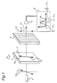
- Fig. 1 shows a diagram of a polarization state detector of a first embodiment
- Figs. 2 and 3 show the graphs of changes in the intensity of a magnetic field to be applied.
- the polarization state detector comprises a Faraday cell 1 made of a magneto-optical crystal such as (BiYGd)IG, a polarizer 2, and an optical receiver 7 successively arranged in this order from the side of incident light along the optical axis 11.
- Faraday cell 1 is controlled by an external magnetic field H so that its direction of rotation (angle of rotation ⁇ ) can be varied all over one complete rotation around the optical axis.
- Polarizer 2 is set to a base direction for analyzing the polarization state, that is, to the vertical 12 in the present invention.
- Optical receiver 7 receives linearly polarized light 6 that has passed through polarizer 2 to send a signal of the received level of light at any time to a signal analyzer 8 for analyzing the polarization state.
- Signal analyzer 8 analyzes the polarization state of the incident light based on the relation between the difference between the angle ⁇ of Faraday rotation and the set angle of the polarizer and the received level of light.
- the sign of the direction of rotation around the optical axis is defined as positive, if the observer is looking in the direction the light is traveling, and the rotation is counter-clockwise. The angle is measured in units of radians.
- Fig. 1 suppose incident light 4 transmitted through an optical fiber is linearly polarized light inclined by ⁇ 1 9 from set direction 12 of polarizer 2. Then the light that has passed through Faraday cell 1 becomes linearly polarized light 5 having inclination ⁇ 1 + ⁇ from set direction 12 of polarizer 2. Further, light 6 that has passed through polarizer 2 after emitted from Faraday cell 1 shows a change of intensity proportional to ⁇ cos2( ⁇ 1 + ⁇ ) + 1 ⁇ ⁇ 2 from the intensity of the incident light. This value is shown in signal analyzer 8 for analyzing the polarization state in Fig. 1 by a graphical representation, where the abscissa is ⁇ .
- a minimum change in the intensity of the received light is obtained, when the plane of polarization of incident light 4 is changed to be perpendicular to the set angle of polarizer 2 by Faraday rotation.
- a maximum change is obtained, when the plane of polarization is changed to be parallel to the set angle.
- incident light is linearly polarized light inclined by ⁇ 1.
- linearly polarized light 24 that has passed through polarizer 2 of the polarizing state detector shows a change of intensity proportional to ⁇ cos2( ⁇ m + ⁇ ) + 1 ⁇ ⁇ 2 from the intensity of the incident light.
- a signal analyzer 19 for optical calculation compares the phase change ⁇ + ⁇ m of above output 24 with the phase angle ⁇ m of Faraday rotation for modulation to calculate the phase difference ⁇ , which is the angle of Faraday rotation for detection, and determines current to be measured.
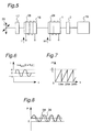
- FIG. 5 shows a block diagram of the second embodiment.
- a coil 28 for detection is wound around Faraday cell 18 for detection, and a coil 29 for modulation is wound around Faraday cell 1 for modulation.
- Magnetic field H for detection is generated by applying current to be measured I
- magnetic field H m for modulation is generated by applying a current I m for modulation.
- current to be measured I has a sine waveform of amplitude a, frequency f, and initial phase angle ⁇ 36, as shown in Fig. 6.
- a current sensor of a third embodiment is described with reference to Figs. 9 and 10.
- the third embodiment is the same as the second embodiment in that a first polarizer 17, a Faraday cell 18 for detection, a Faraday cell for modulation 1, and a polarizer 2 of the above polarization state detector are arranged in this order along the optical axis.
- an integrator 43 that inputs current to be measured I to itself and performs an integrating operation to output magnetic field for detection is installed between Faraday cell 18 and current to be measured I.
- obtaining magnetic field 27 that varies by a change equivalent to the integral value of current to be measured 30 suffices.
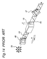
- This unit is mounted on the electric cable using a center hole 100 formed at the head portion thereof.
- An arch-like magnetic core 102 is arranged in a case so that it surrounds the electric cable and a current sensor module 104 is arranged between free ends of the magnetic core 104 so that a magnetic field generated by a current flowing through the electric cable and trapped by the magnetic core 102 is applied thereto.
- An incident light from a light source such as LED is introduced into this module from an optical fiber cable 106 and an output light having passed through the module 104 is sent through the optical fiber cable 106 to the signal analyzer 19 or 40 (not shown in this figure) to detect the intensity of the current flowing through the cable.
Landscapes
- Engineering & Computer Science (AREA)
- Power Engineering (AREA)
- Physics & Mathematics (AREA)
- General Physics & Mathematics (AREA)
- Condensed Matter Physics & Semiconductors (AREA)
- Measuring Instrument Details And Bridges, And Automatic Balancing Devices (AREA)
Applications Claiming Priority (4)
| Application Number | Priority Date | Filing Date | Title |
|---|---|---|---|
| JP30540792 | 1992-11-16 | ||
| JP305407/92 | 1992-11-16 | ||
| JP31220092 | 1992-11-20 | ||
| JP312200/92 | 1992-11-20 |
Publications (2)
| Publication Number | Publication Date |
|---|---|
| EP0598356A2 true EP0598356A2 (fr) | 1994-05-25 |
| EP0598356A3 EP0598356A3 (fr) | 1995-03-08 |
Family
ID=26564285
Family Applications (1)
| Application Number | Title | Priority Date | Filing Date |
|---|---|---|---|
| EP93118355A Withdrawn EP0598356A3 (fr) | 1992-11-16 | 1993-11-12 | Détecteur de l'état de polarisation et capteur de courant l'utilisant. |
Country Status (2)
| Country | Link |
|---|---|
| EP (1) | EP0598356A3 (fr) |
| KR (1) | KR940011955A (fr) |
Cited By (2)
| Publication number | Priority date | Publication date | Assignee | Title |
|---|---|---|---|---|
| CN102565509A (zh) * | 2011-12-16 | 2012-07-11 | 西安交通大学 | 多光路反射式光纤电流传感器 |
| CN103115683A (zh) * | 2013-01-22 | 2013-05-22 | 黑龙江工程学院 | 测量单色光偏振态的方法 |
Families Citing this family (1)
| Publication number | Priority date | Publication date | Assignee | Title |
|---|---|---|---|---|
| KR100659564B1 (ko) * | 2004-08-21 | 2006-12-19 | 일진전기 주식회사 | 광 전류센서 |
Family Cites Families (6)
| Publication number | Priority date | Publication date | Assignee | Title |
|---|---|---|---|---|
| US3901603A (en) * | 1974-01-14 | 1975-08-26 | Trw Inc | Polarimeter and polarimetric method |
| FR2547049B1 (fr) * | 1983-06-03 | 1985-08-30 | Sereg Soc | Dispositif de telemesure par polarimetrie |
| JPS62105068A (ja) * | 1985-10-31 | 1987-05-15 | Tokyo Electric Power Co Inc:The | 光式計測装置 |
| JPS62150184A (ja) * | 1985-12-24 | 1987-07-04 | Matsushita Electric Ind Co Ltd | 磁界測定装置 |
| JPS62159065A (ja) * | 1986-01-07 | 1987-07-15 | Toshiba Corp | 磁界測定装置 |
| DE3931543A1 (de) * | 1989-09-21 | 1991-04-04 | Siemens Ag | Polarimeteranordnung |
-
1993
- 1993-11-12 KR KR1019930024004A patent/KR940011955A/ko not_active Ceased
- 1993-11-12 EP EP93118355A patent/EP0598356A3/fr not_active Withdrawn
Cited By (2)
| Publication number | Priority date | Publication date | Assignee | Title |
|---|---|---|---|---|
| CN102565509A (zh) * | 2011-12-16 | 2012-07-11 | 西安交通大学 | 多光路反射式光纤电流传感器 |
| CN103115683A (zh) * | 2013-01-22 | 2013-05-22 | 黑龙江工程学院 | 测量单色光偏振态的方法 |
Also Published As
| Publication number | Publication date |
|---|---|
| EP0598356A3 (fr) | 1995-03-08 |
| KR940011955A (ko) | 1994-06-22 |
Similar Documents
| Publication | Publication Date | Title |
|---|---|---|
| CA1208452A (fr) | Dispositif pour mesurer un dephasage non reciproque dans un interferometre en anneau | |
| US4539521A (en) | Magnetic field measuring device | |
| US5034679A (en) | Polarization feedback control of polarization rotating sensor | |
| EP0351171B1 (fr) | Méthode et appareil pour la mesure optique de quantités électriques et magnétiques | |
| EP1133703B1 (fr) | Detecteur de courant a fibre optique | |
| US6621258B2 (en) | Electro-optic high voltage sensor | |
| CA1328482C (fr) | Systeme electro-optique de mesure de tension utilisant un dispositif pour extraire la forme d'onde de la tension a mesurer de deux signaux electriques dephases | |
| US6362615B1 (en) | Electro-optic voltage sensor for sensing voltage in an E-field | |
| Böhm et al. | Direct rotation-rate detection with a fibre-optic gyro by using digital data processing | |
| US4956607A (en) | Method and apparatus for optically measuring electric current and/or magnetic field | |
| US6204954B1 (en) | Technique for measuring the Vpi-AC of a mach-zehnder modulator | |
| KR100376139B1 (ko) | 광센서 | |
| US5477134A (en) | Voltage sensor for use in optical power transformer including a pair of Pockels cells | |
| EP0691758A1 (fr) | Détection synchrone de signaux optique | |
| UA35606C2 (uk) | Спосіб вимірювання пропускання, кругового дихроїзму, оптичного обертання оптично активних речовин та дихрограф для його здійснення | |
| EP0598356A2 (fr) | Détecteur de l'état de polarisation et capteur de courant l'utilisant | |
| EP0535164B1 (fr) | Demodulation de source de signaux de reference | |
| JP3137468B2 (ja) | 光学素子を用いた電気信号の測定装置 | |
| JP3179316B2 (ja) | 光センサ | |
| EP0636891A2 (fr) | Procédé, circuit et dispositif de détection de différence des phases | |
| KR100228416B1 (ko) | 광(光)을 이용한 일체형 전류/전압 측정장치 | |
| JPH06207858A (ja) | 偏光状態検出器およびそれを用いた電流センサ | |
| JP3201729B2 (ja) | 光センサシステムの使用方法 | |
| CA2138598A1 (fr) | Methode d'evaluation polarimetrique de signaux lumineux modules en polarisation | |
| Hirose et al. | A new current measurements system using an azimuth angle modulation method |
Legal Events
| Date | Code | Title | Description |
|---|---|---|---|
| PUAI | Public reference made under article 153(3) epc to a published international application that has entered the european phase |
Free format text: ORIGINAL CODE: 0009012 |
|
| 17P | Request for examination filed |
Effective date: 19931112 |
|
| AK | Designated contracting states |
Kind code of ref document: A2 Designated state(s): DE FR GB |
|
| PUAL | Search report despatched |
Free format text: ORIGINAL CODE: 0009013 |
|
| AK | Designated contracting states |
Kind code of ref document: A3 Designated state(s): DE FR GB |
|
| STAA | Information on the status of an ep patent application or granted ep patent |
Free format text: STATUS: THE APPLICATION HAS BEEN WITHDRAWN |
|
| 18W | Application withdrawn |
Withdrawal date: 19950314 |
|
| R18W | Application withdrawn (corrected) |
Effective date: 19950314 |