EP0598571B1 - Appareil d'individualisation de documents - Google Patents
Appareil d'individualisation de documents Download PDFInfo
- Publication number
- EP0598571B1 EP0598571B1 EP93309082A EP93309082A EP0598571B1 EP 0598571 B1 EP0598571 B1 EP 0598571B1 EP 93309082 A EP93309082 A EP 93309082A EP 93309082 A EP93309082 A EP 93309082A EP 0598571 B1 EP0598571 B1 EP 0598571B1
- Authority
- EP
- European Patent Office
- Prior art keywords
- section
- belt runs
- downstream
- upstream
- belt
- Prior art date
- Legal status (The legal status is an assumption and is not a legal conclusion. Google has not performed a legal analysis and makes no representation as to the accuracy of the status listed.)
- Expired - Lifetime
Links
Images

Classifications
-
- B—PERFORMING OPERATIONS; TRANSPORTING
- B65—CONVEYING; PACKING; STORING; HANDLING THIN OR FILAMENTARY MATERIAL
- B65H—HANDLING THIN OR FILAMENTARY MATERIAL, e.g. SHEETS, WEBS, CABLES
- B65H3/00—Separating articles from piles
- B65H3/02—Separating articles from piles using friction forces between articles and separator
- B65H3/04—Endless-belt separators
-
- B—PERFORMING OPERATIONS; TRANSPORTING
- B65—CONVEYING; PACKING; STORING; HANDLING THIN OR FILAMENTARY MATERIAL
- B65H—HANDLING THIN OR FILAMENTARY MATERIAL, e.g. SHEETS, WEBS, CABLES
- B65H3/00—Separating articles from piles
- B65H3/46—Supplementary devices or measures to assist separation or prevent double feed
- B65H3/52—Friction retainers acting on under or rear side of article being separated
- B65H3/5246—Driven retainers, i.e. the motion thereof being provided by a dedicated drive
-
- B—PERFORMING OPERATIONS; TRANSPORTING
- B65—CONVEYING; PACKING; STORING; HANDLING THIN OR FILAMENTARY MATERIAL
- B65H—HANDLING THIN OR FILAMENTARY MATERIAL, e.g. SHEETS, WEBS, CABLES
- B65H2301/00—Handling processes for sheets or webs
- B65H2301/30—Orientation, displacement, position of the handled material
- B65H2301/32—Orientation of handled material
- B65H2301/321—Standing on edge
-
- B—PERFORMING OPERATIONS; TRANSPORTING
- B65—CONVEYING; PACKING; STORING; HANDLING THIN OR FILAMENTARY MATERIAL
- B65H—HANDLING THIN OR FILAMENTARY MATERIAL, e.g. SHEETS, WEBS, CABLES
- B65H2301/00—Handling processes for sheets or webs
- B65H2301/40—Type of handling process
- B65H2301/42—Piling, depiling, handling piles
- B65H2301/423—Depiling; Separating articles from a pile
- B65H2301/4237—Depiling; Separating articles from a pile of vertical articles, e.g. by extracting articles laterally from the pile
-
- B—PERFORMING OPERATIONS; TRANSPORTING
- B65—CONVEYING; PACKING; STORING; HANDLING THIN OR FILAMENTARY MATERIAL
- B65H—HANDLING THIN OR FILAMENTARY MATERIAL, e.g. SHEETS, WEBS, CABLES
- B65H2701/00—Handled material; Storage means
- B65H2701/10—Handled articles or webs
- B65H2701/19—Specific article or web
- B65H2701/1916—Envelopes and articles of mail
Definitions
- This invention is generally concerned with document singulating apparatus and more particularly with singulating apparatus including opposed, oppositely moving belts for singulating successive documents fed thereto.
- a mail piece singulating structure has been provided where oppositely moving upper and lower belts have been interleaved to form a nip for separating the successive lowermost mail pieces from mail pieces stacked thereon.
- U.S. Patent No. 4,615,519 entitled MAIL SEPARATING DEVICE issued October 7, 1986 to Holodnak et al.
- a belt structure has been provided for handling vertically oriented mail pieces to assure that only one mail piece at a time is fed into a mail processing machine.
- the belt structure is mounted on bell crank that is resiliently urged toward an adjustable stop member so that a predetermined minimum gap is maintained between the outer surface of the belt of the belt structure and the adjacent surface of a feeding roller regardless of the extent of wear on the belt.
- U.S. Patent No. 4,978,114 entitled “Reverse Belt Singulating Apparatus”, issued December 18, 1990, to Holbrook, discloses a singulator which includes a reverse belt assembly cooperating with a forward drive assembly to singulate documents such as sheets as they are fed from a stack according to the preamble of claim 1.
- the forward drive assembly includes a belt assembly which is mounted to a feeder deck to provide a downstream drive force to a bottom envelope.
- Located above the forward belt drive is a reverse belt drive assembly which includes a first pivot frame supporting a plurality of rollers and a belt for pre-shingling a portion of a bottom group of envelopes, and a second frame assembly co-axially mounted with the upstream end of the first belt assembly for generally independent pivotal motion.
- the second frame assembly also supports a plurality of rollers and a second belt for singulating the bottom most envelopes.
- the present invention aims to provide an improved apparatus for singulating documents, including for example, mail pieces that are varying in surface finish and thickness.
- the invention as disclosed and illustrated herein can successfully singulate documents of varying thickness and/or surface finish with little or no need for any adjustments to compensate for material size or type.
- the invention is defined in claim 1.
- an apparatus for singulating respective documents fed thereto wherein each of the documents is uprightly oriented on an edge thereof and has oppositely facing upright surfaces, and wherein each successive document is slidably movable relative to a next successive document against an interdocument frictional force developed therebetween, and wherein the apparatus comprises first document feeding means including at least two first belts, and first means for moving the first belts downstream relative to a path of travel in vertically spaced first belt runs, and second document feeding means, adjacent the first document feeding means, including at least one second belt and second means for moving the second belt upstream relative to the path of travel in a second belt run.
- the second document feeding means comprises a first section including an upstream end and a downstream end, the upstream end being pivotally mounted to a frame member, the first section also including at least two outboard endless belts therearound, the first section including second means for moving the outboard belts upstream relative to a path of travel in vertically spaced second belt runs.
- biasing means for resiliently biasing the third belt runs of the second section between the first belt runs of the first document feeding means such that the third belt runs are biased into interleaving relationship with the first belt runs, and for resiliently biasing the second belt runs of the first section into contact with the respective documents fed thereto.
- the biasing means enables the first and second sections to be laterally flexed about the coupling means in response to said documents fed thereto.
- the first belt runs exert a downstream frictional force greater than an interdocument frictional force on an upright surface of each successive document for feeding thereof downstream in the path of travel.
- the first section and second section belt runs exert an upstream frictional force greater than the interdocument frictional force on the oppositely facing upright surface of each next successive document for feeding thereof upstream relative to the path of travel.
- the second section belt runs exert an upstream frictional force greater than the first section belt runs, and the downstream frictional force exceeds the upstream frictional force, whereby the first belt runs successively feed each successive document downstream in the path of travel against the interdocument and upstream frictional forces.
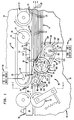
- a singulating apparatus generally designated 10 (Fig. 1), comprises input feeding structure, generally designated 12, for feeding documents of varying thickness 14 from a stack, generally designated 16; document singulating apparatus, generally designated 18, for singulating documents 14 fed thereto; and output feeding structure, generally designated 20, for feeding documents 14 from the singulating structure 18.
- a typical document of varying thickness 14 which may be singulated and fed by the system 10, may comprise an envelope, with or without one or more other documents stuffed therein which are or are not folded, or a sheet, such as a cut sheet, which is or is not folded, or a card, remittance form, mailpiece, or other sheet, or a collation of sheets which are or are not folded.
- each of the documents 14 is preferably uprightly oriented on an edge 22 thereof and has oppositely outwardly facing, upright, surfaces 24 and 26.
- each of the documents 14 fed to the singulating apparatus 18 is slidably movable, out of engagement with the next adjacent document 14, against an interdocument frictional force 28 developed between adjacent ones of surfaces, 24 and 26, in the course of such disengagement.
- the documents 14 are shown as being fed from the stack 16 by means of belt-type input feeding structure 12, such structure 12 is intended to be representative of any document feeding structure which is constructed and arranged to be interfaced with the singulating apparatus 18 for feeding documents 14 fed therefrom.
- the document singulating apparatus 18 generally comprises a conventional framework 30 for supporting the various components of singulating apparatus 18, including a deck, generally designated 32, upon which the respective documents 14 are fed.
- a deck generally designated 32
- the deck 32 is preferably a horizontally-extending conveyor belt 34 (as shown in Fig. 1)
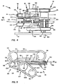
- the deck 32 may be a conventional, horizontally-extending plate 35 (as shown in Figs. 2 and 3), having an upper surface 36 which is coated with a suitable material having a low coefficient of friction, such as teflon or delrin, or the like, with a view to reducing frictional resistance to sliding movement thereon of the lower edges 22 (Fig. 3) of documents 14.
- the document singulating apparatus 18 generally includes a first document feeding structure, generally designated 40, for feeding each successive document 14 downstream along a path of travel 38 on the deck 32, and a second document feeding structure, generally designated 80, for feeding each next successive document 14 upstream relative to the path of travel 38.
- the first document feeding structure 40 preferably includes three endless belts 42 (Figs. 2 and 3).
- first document feeding structure 40 (Fig. 1) includes a pair of vertically oriented, parallel-spaced shafts 44 and 46, which are conventionally journaled to the framework 30 for rotation.
- the upstream shaft 44 is an idler shaft and the downstream shaft 46 is a drive shaft.
- first document feeding structure 40 includes three idler pulleys 48 corresponding to the number of belts 42, and a like number of downstream drive pulleys 50, which are respectively, conventionally mounted for rotation on the upstream and downstream shafts 44 and 46.
- the pulleys 48 and 50 on each shaft 44 and 46 are located at substantially equally vertically-spaced intervals above the deck 32, and thus along the shafts 44 and 46 (Fig 2).
- Each of belts 42 are looped about each pair of pulleys 48 and 50, which are located at the same interval on shafts 44 and 46, respectively, whereby the belts 42 extend substantially horizontally parallel to one another above the deck 32.
- the first feeding structure 40 (Fig. 1) also includes a vertically oriented guide plate 52, which is conventionally fixedly connected to the framework 30 between the upstream and downstream shafts 44 and 46.
- each belt 42 (Fig. 1) includes an upstream belt run, generally designated 54, which extends between an upstream idler pulleys 48 and the midpoint of a guide plate 52, and a downstream belt run, generally designated 56, which extends between the midpoint of guide plate 52 and downstream drive pulleys 50.
- belts 42 (Fig. 2), and thus the respective upstream and downstream belt runs, 54 and 56, are suspended parallel to one another above deck 32 for feeding documents 14 downstream thereon.
- guide plate 52 is parallel to the path of travel 38, and is dimensioned for aligning the downstream belt runs 56 relative to the output feeding structure 20, to support belts 42 and to optimally define the path of travel 38 for feeding documents 14 downstream therein to the output feeding structure 20. It will be understood that a plurality of support rollers could be used in place of guide plate 52 for the same purpose.
- the first document feeding structure 40 additionally includes conventional drive structure 58, including a suitable motor 60, and a conventional gear system 62 interconnecting the motor 60 and downstream drive shaft 46, for driving the shaft 46 to move belts 42 downstream in their respective belt runs 54 and 56 for feeding documents 14 fed thereto downstream in the path of travel 38.
- conventional drive structure 58 including a suitable motor 60, and a conventional gear system 62 interconnecting the motor 60 and downstream drive shaft 46, for driving the shaft 46 to move belts 42 downstream in their respective belt runs 54 and 56 for feeding documents 14 fed thereto downstream in the path of travel 38.
- the second document feeding structure 80 (Figs. 1, 2, 3 and 4) includes two outboard endless belts 82 and two inboard endless belts 84.
- the second document feeding structure 80 includes a first section, generally designated 86, and a second section, generally designated 88.
- First section 86 is connected to second section 88 in a manner that will be described below.
- first section 86 includes upstream and downstream ends, generally designated 90 and 92 respectively.
- Upstream end 90 includes an axle 98, which is coupled to a drive shaft 99.
- Axle 98 and drive shaft 99 are laterally and forwardly-spaced opposite idler shaft 44.
- Drive shaft 99 is conventionally journaled through the framework 30 for rotation in place.
- first section 86 includes two upstream drive pulleys 100, corresponding to the number to the outboard belts 82, which are conventionally mounted for rotation at opposite ends of axle 98.
- Second section 88 includes upstream and downstream ends, generally designated 94 and 96 respectively.
- Downstream end 96 includes an idler shaft 102 which is in vertical alignment with axle 98.
- Idler shaft 102 is shorter in length than axle 98 and is disposed entirely above deck 32 and is not connected to the framework 30. The means by which idler shaft 102 is rotationally displaced will be described below.
- second section 88 includes two downstream idler pulleys 104, corresponding to the number of inboard belts 84. Pulleys 104 are conventionally mounted for rotation at vertically spaced intervals on idler shaft 102, which are between the vertically spaced intervals of pulleys 100 on axle 98.
- Second section 88 is pivotably mounted at its upstream end 94 to the downstream end 92 of first section 86 by a coupling shaft 106.
- Coupling shaft 106 is an idler shaft that is located substantially midway between drive axle 98 and idler shaft 102, is substantially the same length as drive axle 98, but does not extend through framework 30. The means by which coupling shaft 106 is rotationally displaced will be described below.
- coupling shaft 106 includes two double track pulleys 108, corresponding to the number of pairs of outboard belts 82 and inboard belts 84. Each pulley 108 has an outboard belt track 109 and an inboard belt track 111 (Fig.
- Pulleys 108 on coupling shaft 106 are located at vertically-spaced intervals along shaft 106, such that each outboard belt track 109 is in vertical alignment with a corresponding one of pulleys 100, and each inboard belt track 111 is in vertical alignment with a corresponding one of pulleys 104.
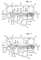
- the diameter of pulleys 104 are smaller than the diameter of pulleys 108 (Figs. 1, 5 and 6).
- first section 86 includes a generally T-shaped first pivot arm 110 for pivotally connecting coupling shaft 106 to drive axle 98.
- first pivot arm 110 is slightly tapered (Fig. 1) horizontally moving from the upstream end 90 to the downstream end 92.
- the upstream end 90 of pivot arm 110 includes a substantially vertically oriented base portion having a vertically oriented aperture 97 through which axle 98 extends.
- Axle 98 is suitably journaled to pivot arm 110.
- the downstream end 92 includes a pair of elongate, parallel-spaced arm members 112 which extend horizontally from the downstream end 92 of first pivot arm 110.
- First pivot arm 110 is conventionally pivotally mounted to coupling shaft 106 through apertures in arm members 112 which are positioned between coupling pulleys 108 such that coupling shaft 106 and coupling pulleys 108 can pivot around axle 98 and drive shaft 99.
- the second section 88 includes a generally H-shaped second pivot arm 89 for pivotally connecting idler shaft 102 to coupling shaft 106.
- second pivot arm 89 is slightly tapered (Fig. 1) horizontally moving from the upstream end 94 to the downstream end 96.
- Second pivot arm 89 includes two pairs of elongate, parallel-spaced arm members 118 and 116 which respectively extend horizontally from the downstream end 96 and the upstream end 94 of second pivot arm 89.
- Second pivot arm 89 is conventionally mounted to idler shaft 102 through apertures in arm members 118 which are positioned between idler pulleys 104. Second pivot arm 89 is conventionally pivotally mounted to coupling shaft 106 through apertures in arm members 116 which are positioned between arm members 112 of first pivot arm 110, whereby first section 86 and second section 88 can pivot in opposite directions about axle 98 and shaft 106, respectively, as documents 14 are fed through singulating apparatus 18.
- second document feeding section 80 conforms to the documents being singulated therefrom.
- Inboard belts 84 are endlessly looped about the pulleys 104 and inboard belt tracks 111 of pulleys 108, whereby the belts 84 extend substantially horizontally parallel to one another, in vertically-spaced intervals above the deck 32. Belts 84 are centered between the horizontally extending intervals in which the belts 42 are located, to permit each of the belts 84 to be interleaved with two of the belts 42.
- second document feeding structure 80 includes an adjustable first spring 128, such as a torsion spring, having one end conventionally connected to the framework 30, as by means of a vertically oriented post 126, and the other end suitably bearing in a first biasing groove 114 of the first section 86 for resiliently and laterally urging the first section 86 and thus, the outboard belts 82, toward the first document feeding structure 40. Since axle 98 operates as a stationary axis for first and second sections 86 and 88, the downstream end 92 of first section 86 is urged toward first feeding structure 40.
- first spring 128 such as a torsion spring
- second document feeding structure 80 includes a second adjustable spring 132, such as a torsion spring, having one end conventionally connected to the framework 30, as by means of a vertically oriented post 130, and the other end suitably bearing in a second biasing groove 120 of the second section 88 for resiliently and laterally urging the second section 88 and thus, inboard belts 84, toward first document feeding structure 40, causing an interleaving relationship with belts 42 of the first document feeding structure 40.
- a second adjustable spring 132 such as a torsion spring
- second section 88 is pivotably mounted at its upstream end 94 to coupling shaft 106 and first section 86 is rotatably mounted at its downstream end 92 to coupling shaft 106, the second document feeding means 80 laterally flexes about coupling shaft 106, deforming springs 128 and 132 when documents 14 pass therethrough.
- the second feeding structure 80 also includes a pair of stop rollers 122 and 124 which are rotatably mounted on coupling shaft 106 and idler shaft 102 respectively for disposition in rolling engagement with the downstream end of the middle one of belts 42. Stop rollers 122 and 124 are dimensioned for laterally aligning the belts 84 with the belts 42 at the downstream end of the downstream belt run 56, whereby the belts 84 thereat are disposed interleaved relationship with the belts 42.
- the diameter of stop rollers 122 and 124 are slightly smaller than the diameter of pulleys 108 and 104 respectively with belts 84 mounted thereon, whereby when stop rollers 122 and 124 engage the middle one of belts 42, belts 84 are in a laterally interleaved relationship with belts 42.
- each belt 82 includes an belt run, generally designated 134, which extends between a guide pulleys 108 and an upstream drive pulleys 100
- each belt 84 includes a belt run 140, which extends between a downstream idler pulleys 104 and guide pulleys 108.
- the belts 82 and 84 (Fig. 3), and thus belt runs 134 and 140 thereof extend parallel to one another, and both belt runs 134 and 140 overhang the deck 32 for feeding documents 14 upstream thereon.
- the second feeding structure 80 (Fig. 1) includes conventional drive structure 142, including a suitable motor 144, and a conventional gear system 146 interconnecting the motor 144 and upstream drive shaft 99, for driving shaft 99 and axle 98 to move the outboard belts 82 and inboard belts 84 upstream in their respective belt-runs, 134 and 140, for feeding documents 14 fed thereto upstream relative to the downstream path of travel 38.
- the counterclockwise rotation of inboard belts 82 and 84 (Figs. 1, 5 and 6) cooperates with springs 128 and 130 to bias second section 88 and the downstream end of first section 86 toward first feeding structure 40.
- the belt runs 140 of belts 84 in second feeding structure 80 are parallel to the belt runs 56 of belts 42 in first feeding structure 40, whereby stop rollers 122 and 124 are biased against the middle one of belts 42 (Fig. 2).
- the belt runs 134 of the second document feeding structure 80 extends progressively upstream and is laterally spaced from the upstream end of, and cooperates with, the upstream belt runs 54 of the first feeding structure 40 to define a wedge-shaped document entry opening, generally designated 150 into which documents 14 are fed into overlapping relationship with one another from the input feeding structure 12.
- the upstream belt runs 54 of the first feeding structure 40 frictionally engage the upright surface 24 of the document 14 fed into engagement therewith, and feed the same downstream relative to the path of travel 38 to a nip 152, formed by the belts 42 and 82, at the juncture of the wedge-shaped opening 150.
- the belt run 134 of the second feeding structure 80 frictionally engages the downstream leading edges 154 of each of the documents 14 within the wedge-shaped opening 150, and tends to feed the documents 14 upstream relative to the path of travel 38.
- the downstream belt runs 56 and belt runs 140 define a second wedge-shaped opening, generally designated 160, having a downstream nip, generally designated 162, which progressively moves downstream until the document 14 is fed downstream to the pulleys 50 and 104 due to the document 14 engaged by the downstream belt runs 56 progressively urging belt runs 140 out of interleaving relationship with the belt runs 56.
- the document 14 when the document 14 is fed to the nip 162 formed by the interleaved belts 42 and 84 at the downstream end of the belt runs 56 and 140 the document 14 then urges the belt 84 out of interleaving relationship with the belts 42, against the resilient urging of the spring 132, whereby the nip 162 is opened. Whereupon the document 14 is fed downstream between the rollers 50 and 104 to the output feeding structure 20 (Fig. 1).
- the above described operation of the singulating structure 18 has been found to reliably occur, for singulating successive documents 14 having the same or varying thickness and surface finish, in substantially all operation cycles.
- the interdocument force 28 (Fig. 1) is such that the upstream force 158 exerted by the belts 84 are insufficient at the nip 152 between the upstream belt runs 54 and belt runs 140, to result in separating the document 14 engaged by the upstream belt run 54 from the next successive document 14.
- two documents 14 are fed downstream beyond the pulleys 108 and guide plate 52.
- the downstream belt runs 56 and belt runs 140 engage the oppositely facing surfaces 24 and 26 of the overlapping documents 14.
- the documents 14 are separated from one another between the belt runs 56 and 140 and, a singulated document 14 is fed downstream from the singulating structure 18 by the downstream belt run 56.
- belts 42 have a high coefficient of friction, such as in rubber belts.
- Belts 82 and 84 have a lower coefficient of friction than belts 42, such as in urethane belts. It will be understood by those skilled in the art that other arrangements of belts for sections 86 and 88 may be suitable for particular applications.
- the important features of the present invention are the combined interleaved and friction feed arrangement of the various belts based on the spacing and location of the belts relative to each other, and the two pivoting sections of the second document feed structure.
- the present invention does not rely solely on the interleaved belt arrangement as in U.S. Patent No. 5,074,540, previously noted.
- the present invention provides two separate pairs of belt runs, one of which is interleaved with the feed belts and one which is opposed to the feed belts. Each of the pair of belt runs pivot on separate axis to accommodate the documents being singulated.
- motors 60 and 144 are conventionally continuously energized for continuously rotating drive shafts 46 and 99 when stream feeding is desired.
- motor 60 is indexed, for example by a stepper motor, and motor 144 is continuously energized for stopping and starting shaft 46 and continuously rotating shaft 99 and axle 98.
- the motor 60 is continuously energized for rotating the drive shaft 46, whereas the motor 144 and gear system 146 may be eliminated, and the belt 82 manually advanced from time-to-time to promote uniform belt wear.
- motors 60 and 144 may both be stepper motors which index belts 42 and 82.
- the moving belt runs 134 and 140 considerably reduce the number of "misses" (i.e., operation cycles in which document singulation does not occur, during a standardized reliability test time period of operation of the singulating structure 18).
Landscapes
- Engineering & Computer Science (AREA)
- Mechanical Engineering (AREA)
- Delivering By Means Of Belts And Rollers (AREA)
Claims (9)
- Appareil (18) pour individualiser des documents (14) amenés à celui-ci, dans lequel chacun desdits documents est orienté debout sur un bord (22) de celui-ci, et comporte des surfaces verticales opposées (24, 26), et dans lequel chaque document successif est mobile par coulissement par rapport à un document successif suivant, à l'encontre d'une force de frottement créée entre eux, l'appareil comprenant des premiers moyens d'amenée de document (40), comportant au moins deux premières bandes (42) et des premiers moyens (46, 50, 60, 62) pour déplacer lesdites premières bandes vers l'aval par rapport à un chemin de déplacement en des premiers passages de bandes espacés verticalement, et des deuxièmes moyens d'amenée de document (80), adjacents auxdits premiers moyens d'amenée de document, lesdits deuxièmes moyens d'amenée de document (80) comportant une première partie (86) ayant une extrémité amont et une extrémité aval, ladite extrémité amont étant montée de façon pivotante sur un organe formant cadre (30), ladite première partie comportant également au moins deux bandes sans fin extérieures (82) autour de celle-ci, et ladite première partie comportant des deuxièmes moyens (98, 100, 144, 146) pour déplacer lesdites bandes extérieures vers l'amont en des deuxièmes passages de bandes espacés verticalement, ledit appareil étant caractérisé par:a) une deuxième partie (88) comportant au moins deux bandes sans fin intérieures (84) autour de celle-ci, ladite deuxième partie ayant une extrémité amont et une extrémité aval; ladite deuxième partie (88) étant montée de façon pivotante à son extrémité amont, sur ladite extrémité aval de ladite première partie (86),b) des moyens (106, 108, 110), pour coupler le mouvement desdites bandes extérieures de ladite première partie auxdites bandes intérieures de ladite deuxième partie, pour entraîner lesdites bandes intérieures de ladite deuxième partie vers l'amont par rapport à un chemin de déplacement en des passages de bandes de deuxième partie espacés verticalement,c) des moyens (128, 132), pour solliciter de façon élastique lesdits passages de bandes de deuxième partie vers une relation intercalée avec lesdits premiers passages de bande, et pour solliciter de façon élastique l'extrémité aval desdits passages de bandes de première partie vers lesdits premiers passages de bandes, lesdits moyens de sollicitation permettant auxdites première et deuxième parties de fléchir latéralement autour desdits moyens de couplage, en réponse auxdits documents qui y sont amenés; etd) lesdits premiers passages de bande étant agencés de manière à exercer une force de frottement vers l'aval supérieure à une force de frottement entre documents sur une surface verticale de chaque document successif, pour amener celui-ci vers l'aval dans ledit chemin de déplacement, lesdits passages de bande de première partie et deuxième partie exerçant une force de frottement vers l'amont supérieure à ladite force de frottement entre documents sur la surface verticale opposée de chaque document successif suivant, pour amener celui-ci vers l'amont par rapport audit chemin de déplacement, et ladite force de frottement vers l'aval dépassant ladite force de frottement vers l'amont, de façon que lesdits premiers passages de bande amènent successivement chaque document successif dans ledit chemin de déplacement, à l'encontre desdites forces de frottement entre documents et vers l'amont.
- Appareil selon la revendication 1, dans lequel ladite deuxième partie (88) comprend en outre un premier et un deuxième rouleaux d'arrêt (122, 124), montés de façon rotative sur les extrémités amont et aval (94, 96) de ladite deuxième partie (88), entre lesdits deuxièmes passages de bande, lesdits premier et deuxième rouleaux d'arrêt étant sollicités de façon à venir en prise de roulement avec l'un desdits premiers passages de bande.
- Appareil selon la revendication 1, dans lequel lesdits moyens (128, 132) de sollicitation élastique comportent un premier ressort (128) couplé à ladite première partie (86), et un deuxième ressort (132) couplé a ladite deuxième partie (88).
- Appareil selon la revendication 2, dans lequel lesdits moyens (128, 132) de sollicitation élastique comportent un premier ressort (128) couplé à ladite première partie, pour solliciter latéralement de façon élastique le premier rouleau d'arrêt (122) de façon à le mettre en prise de roulement avec l'extrémité amont du premier passage de bande, lesdits moyens de sollicitation élastique comportant en outre un deuxième ressort (132) couplé à ladite deuxième partie, pour solliciter latéralement de façon élastique le deuxième rouleau d'arrêt (124) de façon à le mettre en prise de roulement avec l'extrémité aval du premier passage de bande.
- Appareil selon la revendication 1, dans lequel lesdits passages de bande de deuxième partie ( 134) ont une extrémité amont et une extrémité aval, lesdits moyens de sollicitation élastique comportant des moyens (128, 132), pour solliciter indépendamment de façon élastique les extrémités amont et aval desdits passages de bande de deuxième partie vers une relation intercalée avec lesdits premiers passages de bande (56).
- Appareil selon la revendication 1, dans lequel lesdits premiers passages de bande (56) engagent et amènent les feuilles successives vers l'aval dans ledit chemin de déplacement, à l'encontre de la sollicitation élastique dudit deuxième passage de bande vers l'aval.
- Appareil selon la revendication 5, dans lequel lesdits passages de bande de deuxième partie s'étendent sensiblement en alignement avec une partie aval desdits premiers passages de bande, et lesdits passages de bande de première partie s'étendent vers l'amont par rapport auxdits passages de bande de deuxième partie, et sont progressivement plus espacés latéralement d'une partie amont desdits premiers passages de bande, de façon que l'extrémité aval desdits passages de bande de première partie et lesdits premiers passages de bande définissent un pincement (162) entre eux, et de façon que l'extrémité amont desdits premiers passages de bande et lesdits passages de bande de première partie définissent une ouverture d'entrée de document en forme de coin (160), pour recevoir les documents successifs amenés audit appareil d'individualisation.
- Appareil selon la revendication 7, dans lequel lesdits premiers passages de bande (56) amènent des documents successifs amenés à ceux-ci, progressivement vers l'aval de ladite extrémité amont desdits passages de bande de deuxième partie (134), à l'encontre de la sollicitation élastique de l'extrémité amont desdits passages de bande de première partie, de façon que ladite extrémité aval desdits passages de bande de première partie soit déplacée hors de la relation intercalée avec lesdits premiers passages de bande, de façon à ouvrir ledit pincement (162).
- Appareil selon la revendication 8, dans lequel lesdits premiers passages de bande amènent progressivement des documents successifs vers l'aval dans ledit chemin de déplacement, à l'encontre de la sollicitation élastique de l'extrémité aval desdits passages de bande de deuxième partie, de façon que lesdits passages de bande de deuxième partie (82, 84) soient progressivement amenés hors de la relation intercalée avec lesdits premiers passages de bande (56).
Applications Claiming Priority (2)
| Application Number | Priority Date | Filing Date | Title |
|---|---|---|---|
| US974755 | 1992-11-12 | ||
| US07/974,755 US5238236A (en) | 1992-11-12 | 1992-11-12 | Document singulating apparatus for feeding upright documents of varying thickness |
Publications (2)
| Publication Number | Publication Date |
|---|---|
| EP0598571A1 EP0598571A1 (fr) | 1994-05-25 |
| EP0598571B1 true EP0598571B1 (fr) | 1997-07-30 |
Family
ID=25522404
Family Applications (1)
| Application Number | Title | Priority Date | Filing Date |
|---|---|---|---|
| EP93309082A Expired - Lifetime EP0598571B1 (fr) | 1992-11-12 | 1993-11-12 | Appareil d'individualisation de documents |
Country Status (3)
| Country | Link |
|---|---|
| US (1) | US5238236A (fr) |
| EP (1) | EP0598571B1 (fr) |
| DE (1) | DE69312645T2 (fr) |
Families Citing this family (28)
| Publication number | Priority date | Publication date | Assignee | Title |
|---|---|---|---|---|
| US5443359A (en) * | 1993-05-14 | 1995-08-22 | Westinghouse Electric Corp. | Apparatus for separating and delivering flat articles of random length and thickness from a stack |
| US5435538A (en) * | 1994-01-03 | 1995-07-25 | Xerox Corporation | Retard roll with integral torque limiting slip clutch with reversing bias |
| US5427029A (en) * | 1994-01-25 | 1995-06-27 | Professional Control Corporation | Method and apparatus for providing printed labels for large numbers of objects |
| US6003857A (en) * | 1997-10-03 | 1999-12-21 | Pitney Bowes Inc. | Singulating apparatus for a mail handling system |
| US6279895B1 (en) | 1997-10-27 | 2001-08-28 | Unisys Corporation | Feeder with large pseudo-radius |
| US6135441A (en) * | 1997-12-16 | 2000-10-24 | Pitney Bowes Inc. | Two-stage document singulating apparatus for a mail handling system |
| US6076823A (en) * | 1998-04-21 | 2000-06-20 | Unisys Corporation | Tapered-edge separator web for recording feeding |
| US6354583B1 (en) * | 1999-01-25 | 2002-03-12 | Bell & Howell Mail And Messaging Technologies Company | Sheet feeder apparatus and method with throughput control |
| US6328300B1 (en) | 1999-10-04 | 2001-12-11 | Pitney Bowes Inc. | Aligner mechanism for a mail handling system |
| US6276679B1 (en) * | 1999-11-23 | 2001-08-21 | Pitney Bowes Inc. | Floating idler pulley retard system for mixed mail separation |
| GB2363602B (en) * | 2000-04-25 | 2003-10-08 | Macon Man & Design Ltd | Feed singulation device |
| DE10127994A1 (de) * | 2001-06-08 | 2002-12-12 | Francotyp Postalia Ag | Vereinzelungsvorrichtung für flache Gegenstände |
| FR2849188B1 (fr) * | 2002-12-23 | 2005-03-11 | Solystic | Dispositif pour la pesee dynamique d'envois postaux |
| DE10350352B3 (de) * | 2003-10-29 | 2005-01-13 | Siemens Ag | Einrichtung zur Vereinzelung von überlappenden flachen Sendungen |
| EP1547948B2 (fr) * | 2003-12-23 | 2012-11-14 | Böwe Bell & Howell GmbH | Dispositif pour séparer des lettres |
| DE102004037420B3 (de) | 2004-07-30 | 2005-12-15 | Siemens Ag | Vorrichtung zum Herausziehen einzelner flacher Sendungen aus einer Vereinzelungsstrecke |
| US7201369B2 (en) * | 2004-12-09 | 2007-04-10 | Lockheed Martin Corporation | Vertical justification system |
| DE102005012029B3 (de) * | 2005-03-16 | 2006-07-13 | Siemens Ag | Vorrichtung zum Vereinzeln von überlappenden flachen Sendungen |
| DE102007007813B3 (de) * | 2007-02-16 | 2008-01-17 | Siemens Ag | Vorrichtung und Verfahren zum Vereinzeln von flachen Gegenständen |
| US7806398B2 (en) * | 2007-10-03 | 2010-10-05 | Pitney Bowes Inc. | Ingestion guide assembly for augmenting sheet material separation in a singulating apparatus |
| US7611141B2 (en) * | 2007-12-20 | 2009-11-03 | Pitney Bowes Inc. | Top registered item transport system |
| JP5297035B2 (ja) * | 2007-12-20 | 2013-09-25 | キヤノン電子株式会社 | シート給送装置、スキャナ、プリンタ、ファクシミリ、及び複写機 |
| US8016282B2 (en) * | 2007-12-21 | 2011-09-13 | Pitney Bowes Inc. | Transport for singulating items |
| JP2010208800A (ja) * | 2009-03-10 | 2010-09-24 | Toshiba Corp | 給紙装置 |
| US20110101598A1 (en) * | 2009-10-30 | 2011-05-05 | Dunn Frank B | Method of operating a document feeding mechanism to reduce chance of a document jam condition and an apparatus therefor |
| US8905397B2 (en) * | 2013-03-08 | 2014-12-09 | Neopost Technologies | Articulated mail selector |
| TWI577569B (zh) * | 2015-08-11 | 2017-04-11 | 虹光精密工業股份有限公司 | 傳動組件及包括其之事務機 |
| US9845211B1 (en) * | 2016-11-07 | 2017-12-19 | Nautilus Hyosung Inc. | Media separation apparatus |
Family Cites Families (9)
| Publication number | Priority date | Publication date | Assignee | Title |
|---|---|---|---|---|
| US4432540A (en) * | 1981-02-05 | 1984-02-21 | Bell & Howell Company | Mail sorting machine with improved conveyor and envelope separating device |
| US4615519A (en) * | 1985-01-22 | 1986-10-07 | Pitney Bowes Inc. | Mail separating device |
| US4819927A (en) * | 1987-04-02 | 1989-04-11 | Nec Corporation | Flat article feeding apparatus comprising a plurality of reversedly driven and individually urged pulleys |
| US5129642A (en) * | 1988-06-02 | 1992-07-14 | Bell & Howell Company | Controllable document drive and separation system |
| US4909499A (en) * | 1988-12-28 | 1990-03-20 | Pitney Bowes Inc. | Mail singulating apparatus |
| US4930764A (en) * | 1988-12-28 | 1990-06-05 | Pitney Bowes Inc. | Front end feeder for mail handling machine |
| US4978114A (en) * | 1989-11-14 | 1990-12-18 | Pitney Bowes Inc. | Reverse belt singulating apparatus |
| US5092574A (en) * | 1990-09-05 | 1992-03-03 | Pitney Bowes Inc. | Apparatus for feeding sheets |
| US5074540A (en) * | 1990-11-05 | 1991-12-24 | Pitney Bowes Inc. | Document singulating apparatus |
-
1992
- 1992-11-12 US US07/974,755 patent/US5238236A/en not_active Expired - Fee Related
-
1993
- 1993-11-12 EP EP93309082A patent/EP0598571B1/fr not_active Expired - Lifetime
- 1993-11-12 DE DE69312645T patent/DE69312645T2/de not_active Expired - Fee Related
Also Published As
| Publication number | Publication date |
|---|---|
| DE69312645D1 (de) | 1997-09-04 |
| US5238236A (en) | 1993-08-24 |
| DE69312645T2 (de) | 1998-01-02 |
| EP0598571A1 (fr) | 1994-05-25 |
Similar Documents
| Publication | Publication Date | Title |
|---|---|---|
| US5238236A (en) | Document singulating apparatus for feeding upright documents of varying thickness | |
| US5074540A (en) | Document singulating apparatus | |
| US5147092A (en) | Roller-accumulator for sheets | |
| EP0926085B1 (fr) | Double appareil de séparation de documents pour un système de traitement de courrier | |
| US4640506A (en) | Reverse collating machine | |
| CA1111079A (fr) | Dispositif inverseur d'articles | |
| US5033729A (en) | Mechanism for the handling and singulating of flat materials | |
| GB2283730A (en) | Forming collations of two different size documents. | |
| US4524965A (en) | Envelope stacking machine | |
| US5368287A (en) | Ninety degree turn-up apparatus | |
| US5413326A (en) | Apparatus for changing the direction of motion of documents | |
| SG175058A1 (en) | Accumulating apparatus for discrete paper or film objects and related methods | |
| US7841594B2 (en) | Apparatus for altering the orientation and/or direction of sheet material in mailpiece fabrication systems | |
| US7451979B2 (en) | High throughput sheet accumulator | |
| WO1993015989A1 (fr) | Plateau a pression variable pour recepteur de piles | |
| US4564189A (en) | Articulating sheet material conveyor | |
| US4691913A (en) | Separating apparatus for flat objects | |
| US4045018A (en) | Document deskewing apparatus | |
| GB2258458A (en) | Method and apparatus for aligning while changing direction of flat articles | |
| EP0043262B1 (fr) | Dispositif pour alimenter l'objet inférieur d'une pile | |
| CA2003436A1 (fr) | Magasin d'alimentation de cartes | |
| JP2664555B2 (ja) | シート材の送り装置 | |
| US8038149B2 (en) | Alignment/registration and conveyance apparatus | |
| JPH0726289Y2 (ja) | 紙葉類集積装置 | |
| CN101119915A (zh) | 用于将扁平邮件的一条窄边对齐的设备 |
Legal Events
| Date | Code | Title | Description |
|---|---|---|---|
| PUAI | Public reference made under article 153(3) epc to a published international application that has entered the european phase |
Free format text: ORIGINAL CODE: 0009012 |
|
| AK | Designated contracting states |
Kind code of ref document: A1 Designated state(s): DE FR GB |
|
| 17P | Request for examination filed |
Effective date: 19941031 |
|
| 17Q | First examination report despatched |
Effective date: 19960125 |
|
| GRAG | Despatch of communication of intention to grant |
Free format text: ORIGINAL CODE: EPIDOS AGRA |
|
| GRAH | Despatch of communication of intention to grant a patent |
Free format text: ORIGINAL CODE: EPIDOS IGRA |
|
| GRAH | Despatch of communication of intention to grant a patent |
Free format text: ORIGINAL CODE: EPIDOS IGRA |
|
| GRAA | (expected) grant |
Free format text: ORIGINAL CODE: 0009210 |
|
| AK | Designated contracting states |
Kind code of ref document: B1 Designated state(s): DE FR GB |
|
| REF | Corresponds to: |
Ref document number: 69312645 Country of ref document: DE Date of ref document: 19970904 |
|
| ET | Fr: translation filed | ||
| PLBE | No opposition filed within time limit |
Free format text: ORIGINAL CODE: 0009261 |
|
| 26N | No opposition filed | ||
| REG | Reference to a national code |
Ref country code: GB Ref legal event code: IF02 |
|
| PGFP | Annual fee paid to national office [announced via postgrant information from national office to epo] |
Ref country code: GB Payment date: 20071128 Year of fee payment: 15 Ref country code: FR Payment date: 20071119 Year of fee payment: 15 |
|
| PGFP | Annual fee paid to national office [announced via postgrant information from national office to epo] |
Ref country code: DE Payment date: 20071221 Year of fee payment: 15 |
|
| GBPC | Gb: european patent ceased through non-payment of renewal fee |
Effective date: 20081112 |
|
| REG | Reference to a national code |
Ref country code: FR Ref legal event code: ST Effective date: 20090731 |
|
| PG25 | Lapsed in a contracting state [announced via postgrant information from national office to epo] |
Ref country code: DE Free format text: LAPSE BECAUSE OF NON-PAYMENT OF DUE FEES Effective date: 20090603 |
|
| PG25 | Lapsed in a contracting state [announced via postgrant information from national office to epo] |
Ref country code: GB Free format text: LAPSE BECAUSE OF NON-PAYMENT OF DUE FEES Effective date: 20081112 |
|
| PG25 | Lapsed in a contracting state [announced via postgrant information from national office to epo] |
Ref country code: FR Free format text: LAPSE BECAUSE OF NON-PAYMENT OF DUE FEES Effective date: 20081130 |