EP0598685A1 - A vehicle with a safety device for frontal collision - Google Patents
A vehicle with a safety device for frontal collision Download PDFInfo
- Publication number
- EP0598685A1 EP0598685A1 EP93830450A EP93830450A EP0598685A1 EP 0598685 A1 EP0598685 A1 EP 0598685A1 EP 93830450 A EP93830450 A EP 93830450A EP 93830450 A EP93830450 A EP 93830450A EP 0598685 A1 EP0598685 A1 EP 0598685A1
- Authority
- EP
- European Patent Office
- Prior art keywords
- section
- vehicle
- flexible cable
- vehicle according
- energy
- Prior art date
- Legal status (The legal status is an assumption and is not a legal conclusion. Google has not performed a legal analysis and makes no representation as to the accuracy of the status listed.)
- Withdrawn
Links
- 238000006073 displacement reaction Methods 0.000 claims abstract description 9
- 238000006243 chemical reaction Methods 0.000 claims description 7
- 230000000063 preceeding effect Effects 0.000 claims 1
- 230000005540 biological transmission Effects 0.000 description 3
- 238000010521 absorption reaction Methods 0.000 description 2
- 238000004873 anchoring Methods 0.000 description 2
- 238000010276 construction Methods 0.000 description 2
- 230000000694 effects Effects 0.000 description 2
- 238000004519 manufacturing process Methods 0.000 description 2
- 239000002184 metal Substances 0.000 description 2
- 238000005452 bending Methods 0.000 description 1
- 238000013016 damping Methods 0.000 description 1
- 230000000994 depressogenic effect Effects 0.000 description 1
- 238000004088 simulation Methods 0.000 description 1
Images

Classifications
-
- B—PERFORMING OPERATIONS; TRANSPORTING
- B60—VEHICLES IN GENERAL
- B60R—VEHICLES, VEHICLE FITTINGS, OR VEHICLE PARTS, NOT OTHERWISE PROVIDED FOR
- B60R19/00—Wheel guards; Radiator guards, e.g. grilles; Obstruction removers; Fittings damping bouncing force in collisions
-
- B—PERFORMING OPERATIONS; TRANSPORTING
- B62—LAND VEHICLES FOR TRAVELLING OTHERWISE THAN ON RAILS
- B62D—MOTOR VEHICLES; TRAILERS
- B62D21/00—Understructures, i.e. chassis frame on which a vehicle body may be mounted
- B62D21/15—Understructures, i.e. chassis frame on which a vehicle body may be mounted having impact absorbing means, e.g. a frame designed to permanently or temporarily change shape or dimension upon impact with another body
- B62D21/152—Front or rear frames
Definitions
- the present invention is generally related to vehicles having a body comprising a first section placed in the front, which delimits a space wherein a power unit is supported and which is collapsible in the case of frontal collision of the vehicle, a second section placed immediately behind the said first section and delimiting a passenger compartment, said second section having a structure provided with a resistance to collapsing substantially greater than the first section, and a safety device including a flexible and substantially unstretchable cable system operatively connected to the power unit and subject to traction owing to rearward displacement thereof following a frontal collision of a certain amount, so as to operate intervention of said safety device.
- the usefulness of these known devices is limited to the case of low-speed frontal collisions or anyway such as to substantially involve only collapsing of the front section of the body.
- the only expedient nowadays known for reducing the effects of a frontal collision in connection with the body section delimiting the passenger compartment consists of manufacturing the structure of the body front section with high collapsing performances, to the aim of conferring to such a section the maximum capability of absorbing the impact energy. In case of violent crushes this capability is insufficient, which fatally involves structural collapsing of the section delimiting the passenger compartment, with evident consequences deriving thereby for the passengers.
- the object of the present invention is to overcome the above-mentioned drawbacks, and to provide a vehicle of the aforecited type which is adapted to ensure a higher safety degree, in connection both with the driver and the passengers, in the case of frontal collision of the vehicle.
- a further object of the invention is to provide a vehicle of the aforesaid type, provided with a safety device which is able to take advantage, in a simple and functional way, of the backward displacement of the power unit in case of a frontal collision, so as to absorbe the impact energy thus limiting, or at least delaying, collapsing of the body section delimiting the passenger compartment.
- Still a further object of the invention is to provide a safety system adapted to be manufactured in a relatively simple and economical way, and also adapted to be applied on already existing vehicles.
- the above objects are achieved by virtue of a vehicle such as defined at the beginning, essentially characterized in that the safety device comprised of a flexible cable system operatively connected to the power unit, includes energy-absorbing members incorporated within the structure of the said second body section.
- These energy-absorbing members conveniently act along at least one action line which is substantially parallel to the longitudinal axis of the vehicle, and the flexible cable is substantially lying on a plane, preferably horizontal, containing such action line.
- the energy-absorbing members are subdivided in two groups arranged on the opposed sides of the passenger compartment of the vehicle.
- the energy-absorbing members of each group are arranged in series and are aligned along a respective common line of action, and the flexible cable has two branches each of which is placed along the line of action of a respective one of said groups and is operatively connected to each of the energy-absorbing members of such group.
- Each energy-absorbing member is conveniently constituted by a cylindrical tubular body having a collapsible axial wall.
- the flexible cable extends co-axially through each cylindrical tubular body and on one side freely crosses the front end thereof, while on the other side is rigidly anchored to the respective rear end.
- the body section delimiting the passenger compartment of the vehicle includes two lower lateral stiffening girders.
- the cylindrical tubular bodies of the two groups are fitted within apertures formed in two respective reaction plates rigidly fixed to the two stiffening girders and placed on the common horizontal plane of the safety device.
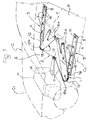
- reference C generally designates the body of a motor vehicle having a first section C1 placed in the front, and a second section C2 placed immediately behind the first section C1.
- the front section C1 delimits a space within which a power unit M, which in the shown example is arranged transverse to the longitudinal axis of the vehicle, is supported in a usual way, normally by means of three securing points with elastic damping supports.
- the second section C2 delimits a passenger compartment A having a driving site including a driver's seat and a steering wheel (not shown in the drawings), at least a further front seat and possibly rear seats (not shown) for the passengers.
- the section C1 has conventionally a frame-like structure provided with a limited resistance to collapsing, in the case of frontal collision, along the longitudinal direction of the car.
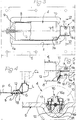
- the second body section C2 is instead provided with a higher resistance to longitudinal collapsing, and in this respect it is constituted in a usual way by a platform P delimited along the sides thereof by a pair of lower lateral stiffening box-like longitudinal members, or girders, L (figure 4). These girders L are normally connected to each other by one or more transverse elements T, onto which the attachment members for the vehicle seats are secured.
- the vehicle is provided with a safety device, generally designated as 1, whose function is to limit the effects of a frontal collision for the occupants of the passenger compartment A.
- the safety device 1 takes advantage of the rearward displacement of the power unit M, generated by the frontal impact and by the consequent collapsing of the front body section C1, so as to actuate intervention of an energy-absorbing system incorporated within the structure of the second body section C2, through a flexible cable transmission 2 operatively linked to the power unit M.
- this energy-absorbing system 1 comprises two groups 3 of energy-absorbing members 4 arranged on the sides of the passenger compartment and, more particularly, placed in correspondence of the two lower lateral girders L of the body section C2,at the level of the platform P.
- Each group 3 is comprised of a sturdy reaction plate 5, placed horizontally and parallel to the respective lateral girder L, which is rigidly fixed, for instance by means of bolts 6 (figure 4), to the structure of the platform P.
- the plate 5 is formed with a number of openings 7, spaced apart from and longitudinally aligned to one another, each of which houses a respective energy-absorbing member 4, constituted by a cylindrical tubular body, normally made of metal, arranged with its axis oriented parallel to the longitudinal direction of the reaction plate 5 and having an axially collapsible lateral wall 8.
- Two opposed conical annular head elements 9, 10 are respectively arranged at the front end and at the rear end of the lateral wall 8, which may be constituted by distinct elements or may be integrally formed with the cylindrical body 4, and which bear against the front edge 7a and against the rear edge 7b, respectively, of the opening 7.
- the flexible cable transmission 2 is constituted, in the shown example, by a single substantially unstretchable metal wire having two lateral branches 12, each of which is arranged along the common axis of the energy-absorbing cylinders 4 of a respective group 3, and is operatively connected, as will be explained hereinbelow, to each of the said energy-absorbing cylinders 4.
- the two lateral branches 12 are joined to each other by an intermediate cable section 11 which is also placed substantially on the plane of the platform P and is linked at 13 to the power unit M.
- such linkage is performed by means of an arm 14 projecting rearwardly from the power unit M, parallel to the longitudinal direction of the vehicle, and to the rear end of which the intermediate cable section 11 is anchored by any suitable way in a rigid or slidable way.
- the arm 14 may possibly carry one of the connecting supports of the power unit M to the structure of the front body section C1 which, in case of a frontal collision, will be subject to breakage owing to backward displacement of said power unit M.
- two arms 15 are provided for, which are arranged horizontally and substantially on the plane of the platform P, and are for instance generally V-shaped and rigidly secured at their respective rear ends 15a onto the transverse elements T of the second body section C2.
- the front ends 15b of the guide arms 15 are rounded, so as to provide bending of the cable 2.
- the ends 15b may be equipped with respective pulleys.
- each lateral branch 12 is co-axially extending, as previously explained, through the energy-absorbing cylinders 4 of the respective group 3, freely and slidably crossing the respective annular front headers 9, while being rigidly anchored to the respective annular rear headers 10.
- This anchoring is performed, for each energy-absorbing member 4, by means of a connecting clamp 16 constituted by a portion 16a fixed to or integrally formed with the rear header 10 and by a portion 16b, which are coupled and clamped therebetween by means of screws 17 so as to clamp the corresponding area of the lateral branch 12 of the cable 2.
- the portions of the lateral branches 12 extending between adjacent energy-absorbing members 4 are substantially located on the plane of the two plates 5, i.e. of the platform P: in this respect, each plate 5 is formed in the areas comprised between the respective openings 7 with depressed zones 18, housing also the corresponding portions 16a of the clamps 16.
- the structure of the front body section C1 is subject to collapsing, and the power unit M is displaced rearwardly towards the body section C2, owing either to the said collapsing or directly to the impact force.
- the arm 14 causes tractioning of the cable 2, whose lateral branches 12 are pulled forwardly along with the respective clamps 16.
- This generates, due to the rear thrust applied by the headers 10 and to the front reaction of the headers 9 against the corresponding front edges 7a of the openings 7 of the plates 5, collapsing in the axial direction of the lateral walls of the cylindrical bodies 4.
- the two groups perform a substantial absorbing action of the impact energy, which prevents, or at least appreciably limits, collapsing of the body section C2 structure, thus contributing to ensure safety for the occupants of the vehicle passenger compartment A.
- a collapsing stroke of 200 millimeters was measured, under an average force of 12000 Kg and an absorbed energy of 2400 Kgm.
- the resulting total collapsing travel was thus of 500 millimeters, with an absorbed energy of 4200 Kgm.
- the energy absorption performed by the six energy-absorbing cylinders 4 having a greater thickness has been evaluated in 3300 Kgm, with a resulting total collapsing stroke of the two body sections C1, C2 of less than 300 millimeters.
Landscapes
- Engineering & Computer Science (AREA)
- Mechanical Engineering (AREA)
- Chemical & Material Sciences (AREA)
- Combustion & Propulsion (AREA)
- Transportation (AREA)
- Body Structure For Vehicles (AREA)
Applications Claiming Priority (2)
| Application Number | Priority Date | Filing Date | Title |
|---|---|---|---|
| ITTO920927 | 1992-11-17 | ||
| ITTO920927A IT1258715B (it) | 1992-11-17 | 1992-11-17 | Veicolo con dispositivo di sicurezza per collisioni frontali. |
Publications (1)
| Publication Number | Publication Date |
|---|---|
| EP0598685A1 true EP0598685A1 (en) | 1994-05-25 |
Family
ID=11410857
Family Applications (1)
| Application Number | Title | Priority Date | Filing Date |
|---|---|---|---|
| EP93830450A Withdrawn EP0598685A1 (en) | 1992-11-17 | 1993-11-09 | A vehicle with a safety device for frontal collision |
Country Status (2)
| Country | Link |
|---|---|
| EP (1) | EP0598685A1 (it) |
| IT (1) | IT1258715B (it) |
Cited By (4)
| Publication number | Priority date | Publication date | Assignee | Title |
|---|---|---|---|---|
| EP0799749A1 (de) * | 1996-04-06 | 1997-10-08 | Dr.Ing.h.c. F. Porsche Aktiengesellschaft | Fangvorrichtung für ein Antriebsaggregat |
| WO2001012494A1 (es) * | 1999-08-11 | 2001-02-22 | Taexpa, S.A. | Sistema perfeccionado para la absorcion de impactos en vehiculos automoviles |
| US6644691B2 (en) * | 2002-02-15 | 2003-11-11 | Mohamed T. Husain | Impact-absorbing apparatus for front ends of vehicles |
| FR2979079A1 (fr) * | 2011-08-19 | 2013-02-22 | Peugeot Citroen Automobiles Sa | Systeme permettant de maintenir un groupe motopropulseur en zone inferieure du vehicule en cas de choc. |
Citations (3)
| Publication number | Priority date | Publication date | Assignee | Title |
|---|---|---|---|---|
| FR1226271A (fr) * | 1959-06-03 | 1960-07-11 | Dispositif de sécurité pour véhicules automobiles | |
| FR2135395A1 (it) * | 1971-05-03 | 1972-12-22 | Peugeot & Renault | |
| EP0324907A1 (de) * | 1988-01-19 | 1989-07-26 | Ag Audi | Anordnung eines frontseitigen Antriebsaggregats in einem Kraftfahrzeug |
-
1992
- 1992-11-17 IT ITTO920927A patent/IT1258715B/it active IP Right Grant
-
1993
- 1993-11-09 EP EP93830450A patent/EP0598685A1/en not_active Withdrawn
Patent Citations (3)
| Publication number | Priority date | Publication date | Assignee | Title |
|---|---|---|---|---|
| FR1226271A (fr) * | 1959-06-03 | 1960-07-11 | Dispositif de sécurité pour véhicules automobiles | |
| FR2135395A1 (it) * | 1971-05-03 | 1972-12-22 | Peugeot & Renault | |
| EP0324907A1 (de) * | 1988-01-19 | 1989-07-26 | Ag Audi | Anordnung eines frontseitigen Antriebsaggregats in einem Kraftfahrzeug |
Cited By (7)
| Publication number | Priority date | Publication date | Assignee | Title |
|---|---|---|---|---|
| EP0799749A1 (de) * | 1996-04-06 | 1997-10-08 | Dr.Ing.h.c. F. Porsche Aktiengesellschaft | Fangvorrichtung für ein Antriebsaggregat |
| US5947223A (en) * | 1996-04-06 | 1999-09-07 | Dr. Ing. H.C.F. Porsche Ag | Restraint for a drive assembly of a motor vehicle |
| WO2001012494A1 (es) * | 1999-08-11 | 2001-02-22 | Taexpa, S.A. | Sistema perfeccionado para la absorcion de impactos en vehiculos automoviles |
| ES2160507A1 (es) * | 1999-08-11 | 2001-11-01 | Taexta S A | Sistema perfeccionado para la absorcion de impactos en vehiculos automoviles. |
| US6676709B1 (en) | 1999-08-11 | 2004-01-13 | Taexpa, S.A. | System for absorbing impacts in motor vehicles |
| US6644691B2 (en) * | 2002-02-15 | 2003-11-11 | Mohamed T. Husain | Impact-absorbing apparatus for front ends of vehicles |
| FR2979079A1 (fr) * | 2011-08-19 | 2013-02-22 | Peugeot Citroen Automobiles Sa | Systeme permettant de maintenir un groupe motopropulseur en zone inferieure du vehicule en cas de choc. |
Also Published As
| Publication number | Publication date |
|---|---|
| IT1258715B (it) | 1996-02-27 |
| ITTO920927A0 (it) | 1992-11-17 |
| ITTO920927A1 (it) | 1994-05-17 |
Similar Documents
| Publication | Publication Date | Title |
|---|---|---|
| US4823905A (en) | Impact actuated safety apparatus for a vehicle | |
| US4836321A (en) | Bracing of vehicle body structures on a resiliently mounted front engine motor vehicle | |
| US4334693A (en) | Independent front wheel suspension for motor vehicles | |
| EP0256273B1 (de) | Sicherheitssystem für Kraftfahrzeuge | |
| US4781398A (en) | Frame unit for vehicles | |
| JP3531767B2 (ja) | 車両用バンパ取付構造 | |
| CA2245851A1 (en) | Front structure of car body, and method of absorbing impact by means of the front structure | |
| US5154253A (en) | Arrangement of a front-mounted drive unit in a motor vehicle | |
| EP1117583B1 (en) | An arrangement which makes it possible to displace a cab of a vehicle | |
| JPH08268322A (ja) | 車 体 | |
| EP1201530B1 (en) | Improved system for absorbing impacts in motor vehicles | |
| US4773674A (en) | Holding arrangement for a steering column of a motor vehicle | |
| US3879073A (en) | Collision force absorbing arrangement in vehicles | |
| EP1106480B1 (en) | Occupant protective apparatus | |
| US7165787B1 (en) | Safety device for motor-vehicle steering column and seat belts | |
| KR100313393B1 (ko) | 캡오버형 차량의 안전장치 | |
| JPH07323737A (ja) | 電気自動車のバッテリ搭載構造 | |
| EP0677436B1 (en) | Arrangement for absorbing vehicle collision energy | |
| KR20020049017A (ko) | 중첩을 피하기 위한 충격 흡수 구조물을 구비하는 자동차,특히 승용차 | |
| US3883167A (en) | Devices for absorbing energy by plastic deformation | |
| CN109094655B (zh) | 一种汽车及其车架 | |
| SU1752628A1 (ru) | Силовой элемент кузова транспортного средства дл поглощени энергии при фронтальном ударе | |
| KR200188712Y1 (ko) | 충돌시 엔진의 측방 밀림을 유도하는 엔진룸 | |
| CN112208473B (zh) | 一种支撑梁机构及汽车 | |
| KR900002661Y1 (ko) | 자동차범퍼 보강재구조 |
Legal Events
| Date | Code | Title | Description |
|---|---|---|---|
| PUAI | Public reference made under article 153(3) epc to a published international application that has entered the european phase |
Free format text: ORIGINAL CODE: 0009012 |
|
| AK | Designated contracting states |
Kind code of ref document: A1 Designated state(s): DE ES FR GB NL SE |
|
| STAA | Information on the status of an ep patent application or granted ep patent |
Free format text: STATUS: THE APPLICATION HAS BEEN WITHDRAWN |
|
| 17P | Request for examination filed |
Effective date: 19940907 |
|
| 18W | Application withdrawn |
Withdrawal date: 19941018 |