EP0598852B1 - Caisse de tete pour pate a papier - Google Patents
Caisse de tete pour pate a papier Download PDFInfo
- Publication number
- EP0598852B1 EP0598852B1 EP92922476A EP92922476A EP0598852B1 EP 0598852 B1 EP0598852 B1 EP 0598852B1 EP 92922476 A EP92922476 A EP 92922476A EP 92922476 A EP92922476 A EP 92922476A EP 0598852 B1 EP0598852 B1 EP 0598852B1
- Authority
- EP
- European Patent Office
- Prior art keywords
- stock
- tube bank
- upstream
- tube
- tubes
- Prior art date
- Legal status (The legal status is an assumption and is not a legal conclusion. Google has not performed a legal analysis and makes no representation as to the accuracy of the status listed.)
- Expired - Lifetime
Links
- 238000011144 upstream manufacturing Methods 0.000 claims abstract description 67
- 238000007865 diluting Methods 0.000 claims abstract description 15
- 239000012895 dilution Substances 0.000 claims abstract description 13
- 238000010790 dilution Methods 0.000 claims abstract description 13
- XLYOFNOQVPJJNP-UHFFFAOYSA-N water Substances O XLYOFNOQVPJJNP-UHFFFAOYSA-N 0.000 claims description 22
- 238000004873 anchoring Methods 0.000 claims description 3
- 238000004891 communication Methods 0.000 claims description 3
- 239000012530 fluid Substances 0.000 claims description 3
- 239000000835 fiber Substances 0.000 description 4
- 238000005086 pumping Methods 0.000 description 3
- 230000002411 adverse Effects 0.000 description 1
- 238000013016 damping Methods 0.000 description 1
- 239000013505 freshwater Substances 0.000 description 1
- 239000007788 liquid Substances 0.000 description 1
- 238000012423 maintenance Methods 0.000 description 1
- 230000007246 mechanism Effects 0.000 description 1
- 238000012986 modification Methods 0.000 description 1
- 230000004048 modification Effects 0.000 description 1
- 230000003134 recirculating effect Effects 0.000 description 1
- 239000000243 solution Substances 0.000 description 1
Images
Classifications
-
- D—TEXTILES; PAPER
- D21—PAPER-MAKING; PRODUCTION OF CELLULOSE
- D21F—PAPER-MAKING MACHINES; METHODS OF PRODUCING PAPER THEREON
- D21F1/00—Wet end of machines for making continuous webs of paper
- D21F1/02—Head boxes of Fourdrinier machines
- D21F1/022—Means for injecting material into flow within the headbox
-
- D—TEXTILES; PAPER
- D21—PAPER-MAKING; PRODUCTION OF CELLULOSE
- D21F—PAPER-MAKING MACHINES; METHODS OF PRODUCING PAPER THEREON
- D21F1/00—Wet end of machines for making continuous webs of paper
- D21F1/02—Head boxes of Fourdrinier machines
-
- D—TEXTILES; PAPER
- D21—PAPER-MAKING; PRODUCTION OF CELLULOSE
- D21F—PAPER-MAKING MACHINES; METHODS OF PRODUCING PAPER THEREON
- D21F1/00—Wet end of machines for making continuous webs of paper
- D21F1/02—Head boxes of Fourdrinier machines
- D21F1/024—Details of the feed chamber
-
- D—TEXTILES; PAPER
- D21—PAPER-MAKING; PRODUCTION OF CELLULOSE
- D21F—PAPER-MAKING MACHINES; METHODS OF PRODUCING PAPER THEREON
- D21F1/00—Wet end of machines for making continuous webs of paper
- D21F1/02—Head boxes of Fourdrinier machines
- D21F1/026—Details of the turbulence section
-
- D—TEXTILES; PAPER
- D21—PAPER-MAKING; PRODUCTION OF CELLULOSE
- D21F—PAPER-MAKING MACHINES; METHODS OF PRODUCING PAPER THEREON
- D21F1/00—Wet end of machines for making continuous webs of paper
- D21F1/02—Head boxes of Fourdrinier machines
- D21F1/028—Details of the nozzle section
-
- D—TEXTILES; PAPER
- D21—PAPER-MAKING; PRODUCTION OF CELLULOSE
- D21F—PAPER-MAKING MACHINES; METHODS OF PRODUCING PAPER THEREON
- D21F1/00—Wet end of machines for making continuous webs of paper
- D21F1/06—Regulating pulp flow
Definitions
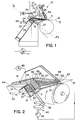
- the present invention relates to a headbox apparatus for ejecting stock onto a forming wire for forming a web. More particularly, the present invention relates to a headbox having means for diluting the stock for controlling the cross-machine directional basis weight of the resultant web.
- stock is ejected from a headbox onto a fourdrinier forming wire which moves at approximately the same speed as the ribbon of stock being ejected from the headbox. Water drains from the stock through the forming wire so that a web is formed on the forming wire.
- An attenuator is disposed upstream relative to the headbox for damping pressure pulses caused by the stock pumping equipment.
- the arrangement is such that the rate of flow of stock entering the headbox is relatively constant.
- the rate of flow of stock is, for example, the number of cubic feet of the stock passing a particular point every minute.
- rate of flow it is necessary in a headbox that such rate of flow remain constant or as constant as possible throughout the headbox.
- the basic reason why the rate of flow should remain constant is that if the stock during preparation has been thoroughly mixed, and if the slice lip opening is the same along the entire cross-machine directional width of the headbox, the weight of the fibers within the stock per inch of width across the ribbon of stock ejected through the slice lip will be constant. Accordingly, the resultant web will have a uniform basis weight in a cross-machine direction.
- the inlet header is tapered in a cross-machine direction so that the cross-sectional area of the inlet header is reduced by an area substantially equal to three times the total cross-sectional area of the tubes of the tube bank immediately upstream of the cross-sectional area of the header. That is, part of the main flow of stock flowing through the inlet header flows through a vertical tier of tubes. Therefore, the inlet is reduced in area by an amount substantially equivalent to three times the cross-sectional area of the tier of tubes in order to compensate for the loss of the diverted flow, thereby maintaining the same pressure in the header in the cross-machine direction to maintain the same flow through the tubes in the cross-machine direction.
- the housing includes an upstream and a downstream port in fluid communication with the tapered inlet.
- the upstream port is connected to the pressurized source of stock.
- the cross-sectional area of the tapered inlet is inversely proportional to the distance from the upstream port.
- the slice chamber also includes a plurality of trailing elements.
- Each trailing element has an end which is pivotally secured to the downstream end of the tube bank.
- Each trailing element is pivotally secured to the tube bank between adjacent rows of the plurality of rows.
- the control means includes a plurality of flow control valves. Each valve cooperates with a conduit such that each of the supply conduits is selectively connected to the stock diluting source for varying the basis weight of the resultant web in a cross-machine direction without changing the flow rate through the tube bank.
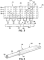
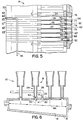
- the tube bank 18 includes a plurality of tubes 24,25,26 and 27 for the flow therethrough of the stock S .
- Figure 5 is an enlarged sectional view of the tube bank 18 showing the tubes 24 to 27 .
- the tube bank 18 defines a plurality of dove-tail shaped grooves 70,71,72 and 73 , as shown in Figure 5.
- Each groove 70 to 72 is disposed betweenadjacent rows 50,51; 51,52; 52,53 of the plurality of rows 50 to 53 .
- the stock diluting source 38 is fresh water or white water removed from the stock through the forming wire 12 and clarified.
- the water flows through the termination 82 such that the water mingles with and dilutes the stock S flowing through the adjacent tube 24 without changing the flow rate through the adjacent tube 24 .
- the stock flows through the tapered inlet 16 of the housing 14 .
- the flow of stock is indicated by the arrow 86 .
- a portion, as indicated by the arrow 90 flows through the upstream portion 54 of the tube 24 .
- a supply conduit 36 is connected to the upstream end 20 of the tube bank 18 so that the conduit 36 has a termination 82 .
- the arrangement is such that water flows, as indicated by the arrow 91 , substantially normal to the flow of stock 86 .
- the flow 91 and 86 mingle together so that substantially all of the water entering through termination 82 flows with the portion of stock 90 through the upstream portion 54 of the tube 24 . Consequently, the stock flowing through tube 24 is diluted. Therefore, the basis weight of the resultant web formed downstream on the forming wire is controlled in a cross-machine direction. More specifically, by such dilution, a sheet having a more uniform basis weight is achieved.
- the present invention provides an accurate means for controlling and maintaining a substantially constant basis weight of a web in a cross-machine direction by dilution of stock flowing through a tube bank.
Landscapes
- Paper (AREA)
- Treatment Of Fiber Materials (AREA)
- Manufacturing And Processing Devices For Dough (AREA)
- Liquid Deposition Of Substances Of Which Semiconductor Devices Are Composed (AREA)
Abstract
Claims (11)
- Un appareil de caisse de tête (10) pour éjecter de la pâte (S) sur une toile de formage (12) pour former une bande (W), ledit appareil comprenant:un logement (14) relié à une source sous pression (P) de pâte (S), ledit logement (14) définissant une entrée effilée (16) pour l'écoulement au travers de la pâte (S);une rangée de tubes (18) ayant une extrémité en amont et une extrémité en aval (20,22), ladite extrémité en amont (20) de ladite rangée de tubes (18) étant reliée à ladite entrée effilée (16) de sorte que la pâte (S) s'écoule à une vitesse d'écoulement essentiellement constante à travers ladite entrée (16) et à travers ladite extrémité en amont (20) de ladite rangée de tubes (18) jusqu'à ladite extrémité en aval (22) de ladite rangée de tubes (18),ladite rangée de tubes (18) comprenant:une pluralité de tubes (24,25,26,27) pour l'écoulement au travers de la pâte (S);un élément (28) définissant une chambre de la règle (30), ladite chambre de la règle (30) ayant une extrémité en amont (32) et une extrémité en aval (34), ladite extrémité en amont (32) étant reliée à ladite extrémité en aval (22) de ladite rangée de tubes (18), ladite extrémité en aval (34) étant disposée adjacente à la toile de formage (12), de sorte que la pâte (S) s'écoule à travers ladite extrémité en aval (22) de ladite rangée de tubes (18) et à travers ladite extrémité en amont (32) de ladite chambre de la règle (30) de sorte que la pâte (S) est éjectée à partir de ladite extrémité en aval (34) de ladite chambre de la règle (30) sur la toile de formage (12);une pluralité de conduits d'alimentation (36,37) reliés à ladite extrémité en amont (20) de ladite rangée de tubes (18), chaque conduit d'alimentation (36,37) de ladite pluralité de conduits d'alimentation étant relié à une source de dilution de la pâte (38) pour permettre la dilution de la pâte (S) s'écoulant dans ladite rangée de tubes (18);un moyen de contrôle (40) coopérant avec lesdits conduits d'alimentation (36,37) pour contrôler ladite dilution de la pâte (S) s'écoulant à travers au moins certains desdits tubes (36,37) de ladite rangée de tubes (18), ledit moyen de contrôle (40) étant structuré et disposé de façon à contrôler le poids de base de la bande résultante dans une direction transversale à la machine;caractérisé par chacun des conduits d'alimentation (36,37) s'étendant à travers ladite rangée de tubes (18) entre des tubes adjacents, chaque conduit ayant une terminaison (82) disposée étroitement adjacente à un tube adjacent de ladite pluralité de tubes et en amont par rapport à ce dernier, ladite terminaison (82) étant disposée adjacente à ladite extrémité en amont (20) de ladite rangée de tubes (18);ladite source de dilution de la pâte (38) étant une eau blanche éliminée de la pâte à travers la toile de formage (12) et clarifiée, ladite eau blanche clarifiée s'écoulant à travers ladite terminaison (82) de sorte que ladite eau blanche clarifiée se mélange avec la pâte (S) s'écoulant à travers ledit tube adjacent (24) et dilue cette dernière sans changer la vitesse d'écoulement à travers ledit tube adjacent (24);chacun desdits conduits d'alimentation et terminaisons respectives étant structuré et disposé de sorte que ledit écoulement d'eau blanche (84) à travers ladite terminaison (82) est essentiellement perpendiculaire à l'écoulement (86) de la pâte (S) au-delà de ladite terminaison (82) en direction dudit tube adjacent (24).
- Un appareil de caisse de tête (10) tel qu'exposé à la revendication 1, caractérisé en ce que ledit moyen de contrôle (40) comprend:
une pluralité de vannes de régulation de l'écoulement (88,89), chaque vanne de ladite pluralité de vannes (88,89) coopérant avec un conduit (36) de ladite pluralité de conduits d'alimentation (36,37) de sorte que chacun desdits conduits d'alimentation (36,37) est sélectivement relié à ladite source de dilution de la pâte (38) pour varier le poids de base de la bande résultante dans une direction transversale à la machine sans changer la vitesse d'écoulement à travers ladite rangée de tubes (18). - Un appareil de caisse de tête (10) tel qu'exposé à la revendication 1, caractérisé en ce que ladite entrée effilée (16) est effilée dans une direction transversale à la machine (CD) de sorte que l'aire, en coupe transversale, pour l'écoulement au travers de la pâte varie progressivement dans une direction transversale à la machine.
- Un appareil de caisse de tête (10) tel qu'exposé à la revendication 3, caractérisé en ce que ledit logement (14) comprend un orifice en amont et un orifice en aval (42,44) en communication de fluide avec ladite entrée effilée (16), ledit orifice en amont (42) étant relié à ladite source sous pression (P) de la pâte (S), ladite aire en coupe transversale de ladite entrée effilée (16) étant inversement proportionnelle à la distance à partir dudit orifice en amont (42).
- Un appareil de caisse de tête (10) tel qu'exposé à la revendication 1, caractérisé en ce que ladite rangée de tubes (18) comprend en outre:
un cadre (48) pour supporter mécaniquement ladite pluralité de tubes (24,25,26,27) de sorte que la pâte (S) s'écoulant à travers ladite entrée (16) et à travers ladite extrémité en amont (20) de ladite rangée de tubes (18) s'écoule à travers ladite pluralité de tubes (24,25,26,27). - Un appareil de caisse de tête (10) tel qu'exposé à la revendication 5, caractérisé en ce que les tubes de ladite pluralité de tubes (24,25,26,27) sont supportés rigidement par ledit cadre (48), lesdits tubes (24,25,26,27) étant disposés dans des rangées espacées verticalement (50,51,52,53), chaque tube à l'intérieur de chaque rangée étant aligné verticalement par rapport à un tube d'une rangée adjacente.
- Un appareil de caisse de cête (10) tel qu'exposé à la revendication 1, caractérisé en ce que chaque tube (24,25,26,27) de ladite pluralité de tubes comprend une portion en amont et une portion en aval (54,56), ladite portion en amont (54) définissant une section essentiellement circulaire prise selon une direction perpendiculaire à la direction de l'écoulement (58) de la pâte (S), ladite portion en aval (56) ayant une extrémité initiale (60) de configuration circulaire en coupe transversale et une extrémité de sortie (62) définissant une configuration essentiellement rectangulaire en coupe transversale pour maintenir un écoulement volumétrique essentiellement constant de pâte à travers ledit tube (26) tout en augmentant la vitesse de l'écoulement de la pâte à travers ladite extrémité de sortie (62).
- Un appareil de caisse de tête (10) tel qu'exposé à la revendication 1, caractérisé en ce que:chaque tube (24,25,26,27) de ladite pluralité de tubes est disposé dans une pluralité de rangées espacées verticalement (50,51,52,53);ladite chambre de la règle (30) comprenant en outre:une pluralité d'éléments traînants (64,65,66,67), chaque élément traînant (64,65,66,67) de ladite pluralité d'éléments traînants ayant une extrémité (68) qui est fixée en pivotement à ladite extrémité en aval (22) de ladite rangée de tube (18), chaque élément traînant (64,65,66,67) étant fixé en pivotement à ladite rangée de tubes (18) entre des rangées adjacentes de ladite pluralité de rangées (50,51,52,53).
- Un appareil de caisse de tête (10) tel qu'exposé à la revendication 8, caractérisé en ce que:ladite rangée de tubes (18) définit une pluralité de cannelures en forme de queue d'aronde (70,71,72,73), chaque cannelure étant disposée entre des rangées adjacentes (50,51;51,52;52,53) de ladite pluralité de rangées (50,51,52,53);chaque élément traînant définissant dans le voisinage de ladite extrémité fixée en pivotement (68) de celui-ci un élargissement (74) qui coopère avec une desdites cannelures pour fixer en pivotement ledit élément (67) à l'intérieur de ladite cannelure de sorte que la pâte (S) s'écoulant à travers ladite extrémité en amont (32) de ladite chambre de la règle (30) est séparée en une pluralité de jets (76,77,78,79) répartis les uns par rapport aux autres par ladite pluralité d'éléments traînants (64,65,66).
- Un appareil de caisse de tête (10) tel qu'exposé à la revendication 9, caractérisé en ce que ladite chambre de la règle (30) converge dans une direction allant de ladite extrémité en amont (32) jusqu'à ladite extrémité en aval (34), de sorte que les jets de ladite pluralité de jets (76,77,78,79) à l'intérieur de ladite chambre de la règle (30) convergent les uns par rapport aux autres.
- Un appareil de caisse de tête (10) tel qu'exposé à la revendication 1, caractérisé en ce que ladite pluralité de conduits d'alimentation s'étend à travers ladite rangée de tubes (18) entre des tubes adjacents de ladite pluralité de tubes.
Priority Applications (1)
| Application Number | Priority Date | Filing Date | Title |
|---|---|---|---|
| DE9218440U DE9218440U1 (de) | 1991-10-29 | 1992-09-30 | Stoffauflauf-Vorrichtung |
Applications Claiming Priority (3)
| Application Number | Priority Date | Filing Date | Title |
|---|---|---|---|
| US784288 | 1985-10-04 | ||
| US07/784,288 US5196091A (en) | 1991-10-29 | 1991-10-29 | Headbox apparatus with stock dilution conduits for basis weight control |
| PCT/US1992/008361 WO1993009286A1 (fr) | 1991-10-29 | 1992-09-30 | Caisse de tete pour pate a papier |
Publications (2)
| Publication Number | Publication Date |
|---|---|
| EP0598852A1 EP0598852A1 (fr) | 1994-06-01 |
| EP0598852B1 true EP0598852B1 (fr) | 1996-04-24 |
Family
ID=25131975
Family Applications (1)
| Application Number | Title | Priority Date | Filing Date |
|---|---|---|---|
| EP92922476A Expired - Lifetime EP0598852B1 (fr) | 1991-10-29 | 1992-09-30 | Caisse de tete pour pate a papier |
Country Status (17)
| Country | Link |
|---|---|
| US (1) | US5196091A (fr) |
| EP (1) | EP0598852B1 (fr) |
| JP (1) | JP2604683B2 (fr) |
| KR (1) | KR100197311B1 (fr) |
| CN (1) | CN1032266C (fr) |
| AR (1) | AR247434A1 (fr) |
| AT (1) | ATE137279T1 (fr) |
| AU (1) | AU660728B2 (fr) |
| BR (1) | BR9206691A (fr) |
| CA (1) | CA2120934C (fr) |
| DE (1) | DE69210246T2 (fr) |
| FI (1) | FI110329B (fr) |
| MX (1) | MX9206229A (fr) |
| PL (1) | PL169274B1 (fr) |
| TW (1) | TW204385B (fr) |
| WO (1) | WO1993009286A1 (fr) |
| ZA (1) | ZA928316B (fr) |
Families Citing this family (50)
| Publication number | Priority date | Publication date | Assignee | Title |
|---|---|---|---|---|
| DE4320243C2 (de) * | 1993-06-18 | 1996-02-22 | Voith Sulzer Papiermasch Gmbh | Stoffauflauf für eine Papiermaschine |
| DE4323263C2 (de) * | 1993-07-12 | 2001-11-29 | Voith Paper Patent Gmbh | Verfahren zur sektionalen Beeinflussung der Stoffdichte und der Faserorientierung in einem Stoffauflauf einer Papiermaschine und Stoffauflauf zur Durchführung des Verfahrens |
| FR2714403A1 (fr) * | 1993-12-23 | 1995-06-30 | Chleq Frote | Dispositif et procédé d'introduction et de réglage fin du débit d'une suspension fibreuse distribuée par une caisse de tête sur une table de formation d'une machine à papier. |
| ES2106592T3 (es) * | 1994-05-13 | 1997-11-01 | Voith Sulzer Papiermasch Gmbh | Dispositivo de alimentacion de pasta para una maquina de fabricacion de papel, con adicion local y mezcla de un fluido. |
| DE4422907C2 (de) * | 1994-06-30 | 1997-03-06 | Voith Gmbh J M | Sektionale Stoffzuführung des Stoffauflaufs einer Papiermaschine |
| US5549793A (en) * | 1994-08-02 | 1996-08-27 | Abb Industrial Systems, Inc. | Control of dilution lines in a dilution headbox of a paper making machine |
| DE4437181C2 (de) * | 1994-10-18 | 1997-02-27 | Voith Sulzer Papiermasch Gmbh | Stoffauflauf für eine Papiermaschine |
| US5560807A (en) * | 1995-03-29 | 1996-10-01 | Beloit Technologies, Inc. | Headbox additive injection system |
| US5626722A (en) * | 1995-06-01 | 1997-05-06 | Valmet Corporation | Headbox of a paper/board machine |
| US5603806A (en) * | 1995-06-01 | 1997-02-18 | Valmet Corporation | Method and apparatus for lateral alignment of the cross-direction quality profile of a web in a paper machine |
| US6425984B2 (en) | 1995-10-20 | 2002-07-30 | Institute Of Paper Science And Technology, Inc. | Layered fiber structure in paper products |
| US6406595B1 (en) | 1995-10-20 | 2002-06-18 | Institute Of Paper Science And Technology, Inc. | Methods and apparatus to enhance paper and board forming qualities |
| US5792321A (en) * | 1995-10-20 | 1998-08-11 | Institute Of Paper Science & Technology, Inc. | Methods and apparatus to enhance paper and board forming qualities |
| US6153057A (en) * | 1995-10-20 | 2000-11-28 | Institute Of Paper Science And Technology, Inc. | Methods and apparatus to enhance paper and board forming qualities |
| US6368460B1 (en) | 1995-10-20 | 2002-04-09 | Institute Of Paper Science And Technology, Inc. | Method and apparatus to enhance paper and board forming qualities |
| DE59608786D1 (de) | 1995-11-17 | 2002-04-04 | Voith Paper Patent Gmbh | Verfahren zur Beeinflussung des Reisslängen-Querprofiles einer laufenden Faserstoffbahn |
| SE506322C2 (sv) * | 1996-03-08 | 1997-12-01 | Valmet Karlstad Ab | Anordning för matning av mäld till en inloppslåda i en pappersmaskin |
| US5853545A (en) * | 1996-03-08 | 1998-12-29 | Valmet-Karlstad Ab | Arrangement for feeding stock to a headbox in a papermaking machine |
| US6235159B1 (en) | 1996-06-10 | 2001-05-22 | Beloit Technologies, Inc. | Convergent flow headbox |
| US5882482A (en) * | 1996-06-10 | 1999-03-16 | Beloit Technologies, Inc. | Convergent flow headbox |
| FI98938C (fi) * | 1996-06-20 | 1997-09-10 | Valmet Corp | Laitteisto laimennusvirtauksen yhdistämiseksi paperikoneen/kartonkikoneen jakotukista johdettuun massavirtaukseen |
| DE19634993A1 (de) * | 1996-08-30 | 1998-03-05 | Voith Sulzer Papiermasch Gmbh | Verfahren und Vorrichtung zum Einstellen des Stoffdichte- und Faserorientierungsprofils in einem Stoffauflauf |
| US5888353A (en) * | 1996-10-03 | 1999-03-30 | Beloit Technologies, Inc. | Flatsided parabolic header for headboxes |
| US5792322A (en) * | 1996-12-03 | 1998-08-11 | Beloit Technologies, Inc. | Flow splitting device for web profile control stock dilution system |
| DE19650588A1 (de) * | 1996-12-06 | 1998-06-10 | Voith Sulzer Papiermasch Gmbh | Stoffauflauf einer Papiermaschine |
| US6113741A (en) * | 1996-12-06 | 2000-09-05 | Eka Chemicals Ab | Process for the production of paper |
| DE19654390A1 (de) * | 1996-12-27 | 1998-07-02 | Basf Ag | Verfahren zur Herstellung von Papier |
| FI115645B (fi) * | 1997-01-14 | 2005-06-15 | Metso Paper Inc | Paperikoneen perälaatikko, jossa on reunasyöttöjärjestelyt |
| US5833808A (en) * | 1997-01-21 | 1998-11-10 | Beloit Technologies, Inc. | Method of controlling curl employing inline headbox edge flow control valve |
| US5944957A (en) * | 1997-03-14 | 1999-08-31 | Valmet Corporation | Regulations system in a paper machine for controlling variation of the basis weight of the paper in the machine direction |
| FI971126A7 (fi) * | 1997-03-18 | 1998-09-19 | Valmet Corp | Paperikoneen perälaatikon laimennusveden käsittely- ja kiertojärjestelmä |
| WO1999011859A1 (fr) * | 1997-09-04 | 1999-03-11 | Beloit Technologies, Inc. | Dispositif permettant d'augmenter la resistance interne d'une bande |
| US6004431A (en) * | 1998-02-24 | 1999-12-21 | Beloit Technologies, Inc. | Headbox with active local flow control |
| FI116078B (fi) * | 1998-12-30 | 2005-09-15 | Metso Paper Inc | Menetelmä massan syöttämiseksi perälaatikkoon |
| US6270625B1 (en) * | 1999-06-29 | 2001-08-07 | The Mead Corporation | Method for manufacturing colored stripped paper |
| RU2182102C2 (ru) * | 1999-12-17 | 2002-05-10 | Открытое акционерное общество Таганрогский авиационный научно-технический комплекс им. Г.М. Бериева | Легкоразъемный узел крепления кресла на летательном аппарате |
| JP3530499B2 (ja) * | 2001-03-19 | 2004-05-24 | 三菱重工業株式会社 | チューブバンク構造及びフローチューブの製造方法 |
| DE60103990T2 (de) * | 2001-06-26 | 2005-07-14 | Hogenkamp Research Inc., Gulf Breeze | Stoffauflauf für Papiermaschine mit verbesserter Düse für Papierstoff |
| FI111397B (fi) * | 2001-12-12 | 2003-07-15 | Metso Paper Inc | Menetelmä ja laite kemikaalin syöttämiseksi kuitususpensioon |
| ZA200508659B (en) * | 2003-05-09 | 2007-03-28 | Akzo Nobel Nv | A process for the production of paper |
| US7599377B2 (en) * | 2004-10-15 | 2009-10-06 | Temic Automotive Of North America, Inc. | System and method for tunneling standard bus protocol messages through an automotive switch fabric network |
| PL205833B1 (pl) * | 2005-04-26 | 2010-05-31 | Pmpoland Spo & Lstrok Ka Akcyj | Skrzynia wlewowa |
| CA2641256C (fr) | 2006-02-01 | 2010-09-28 | Astenjohnson, Inc. | Caisse de tete et systeme d'alimentation en pate de machine a papier |
| ITFI20060267A1 (it) * | 2006-10-30 | 2008-04-30 | Toscotec S P A | Dispositivo per regolare il profilo di grammatura trasversale della carta |
| US8795473B2 (en) * | 2007-12-11 | 2014-08-05 | Paperchine Inc. | Tube bank apparatus for distributing stock |
| US7955474B2 (en) * | 2007-12-11 | 2011-06-07 | Paperchine Inc. | Tube bank apparatus for distributing stock |
| US7871493B2 (en) * | 2008-06-26 | 2011-01-18 | Kimberly-Clark Worldwide, Inc. | Environmentally-friendly tissue |
| DE102009028385A1 (de) * | 2009-08-10 | 2011-02-17 | Voith Patent Gmbh | Verfahren zum Betreiben einer Blattbildungseinheit und Blattbildungseinheit |
| FI11080U1 (fi) | 2015-11-23 | 2015-12-29 | Valmet Technologies Oy | Laimennuselementti kuiturainakoneen perälaatikkoa varten |
| CN108166302A (zh) * | 2018-01-10 | 2018-06-15 | 浙江山鹰纸业有限公司 | 一种用于双网纸机的流浆箱 |
Family Cites Families (15)
| Publication number | Priority date | Publication date | Assignee | Title |
|---|---|---|---|---|
| US3407114A (en) * | 1965-01-04 | 1968-10-22 | Paul F. Springuel | Cross machine control in papermaking |
| US3547775A (en) * | 1966-04-29 | 1970-12-15 | Industrial Nucleonics Corp | Means and method for modulating fiber stock flow in papermaking headbox in response to paper sheet product parameters |
| US3628589A (en) * | 1968-01-31 | 1971-12-21 | Time Inc | Flow systems |
| US3652392A (en) * | 1969-11-24 | 1972-03-28 | Kimberly Clark Co | Contracting pre-slice flow distributor for papermaking machine headbox |
| CA936722A (en) * | 1970-08-31 | 1973-11-13 | A. Betley Raymond | Headbox slice chamber |
| US3791918A (en) * | 1972-03-08 | 1974-02-12 | Valmet Oy | Headbox of a paper making machine having multiple, vertically inclined vanes |
| US4133715A (en) * | 1977-03-29 | 1979-01-09 | Beloit Corporation | Headbox and holders for floating slice chamber dividers |
| FI66931C (fi) * | 1983-01-04 | 1984-12-10 | Tampella Oy Ab | Haolskiva foer en inloppslaoda foer en pappersmaskin |
| DE8520836U1 (de) * | 1984-08-22 | 1986-01-02 | Sulzer-Escher Wyss GmbH, 7980 Ravensburg | Führungsteil für den Stoffauflauf einer Papiermaschine |
| DE3514554C3 (de) * | 1984-09-19 | 1998-01-08 | Escher Wyss Gmbh | Stoffauflauf-Vorrichtung für eine Papiermaschine und Verfahren zu deren Betrieb |
| DE3741603A1 (de) * | 1987-12-09 | 1989-06-22 | Voith Gmbh J M | Stoffauflauf fuer eine papiermaschine od.dgl. |
| FR2631353A1 (fr) * | 1988-05-13 | 1989-11-17 | Semti | Dispositif d'alimentation en melange pateux |
| AT392989B (de) * | 1988-05-17 | 1991-07-25 | Voith Ag J M | Stoffauflauf fuer papiermaschinen |
| FI79363C (fi) * | 1988-09-26 | 1989-12-11 | Valmet Paper Machinery Inc | Foerfarande och anordning i inloppslaodan av en pappersmaskin foer att behaerska foerdelningen i pappersbanans fiberorientering. |
| DE9115296U1 (de) * | 1991-12-10 | 1992-03-19 | J.M. Voith Gmbh, 7920 Heidenheim | Stoffauflauf |
-
1991
- 1991-10-29 US US07/784,288 patent/US5196091A/en not_active Expired - Fee Related
-
1992
- 1992-09-30 EP EP92922476A patent/EP0598852B1/fr not_active Expired - Lifetime
- 1992-09-30 CA CA002120934A patent/CA2120934C/fr not_active Expired - Fee Related
- 1992-09-30 PL PL92303136A patent/PL169274B1/pl unknown
- 1992-09-30 JP JP5508412A patent/JP2604683B2/ja not_active Expired - Fee Related
- 1992-09-30 AU AU27982/92A patent/AU660728B2/en not_active Ceased
- 1992-09-30 WO PCT/US1992/008361 patent/WO1993009286A1/fr not_active Ceased
- 1992-09-30 KR KR1019940701388A patent/KR100197311B1/ko not_active Expired - Fee Related
- 1992-09-30 AT AT92922476T patent/ATE137279T1/de active
- 1992-09-30 BR BR9206691A patent/BR9206691A/pt not_active IP Right Cessation
- 1992-09-30 DE DE69210246T patent/DE69210246T2/de not_active Expired - Fee Related
- 1992-10-27 AR AR92323519A patent/AR247434A1/es active
- 1992-10-28 ZA ZA928316A patent/ZA928316B/xx unknown
- 1992-10-28 MX MX9206229A patent/MX9206229A/es unknown
- 1992-10-28 TW TW081108588A patent/TW204385B/zh active
- 1992-10-29 CN CN92112550A patent/CN1032266C/zh not_active Expired - Fee Related
-
1994
- 1994-04-28 FI FI941961A patent/FI110329B/fi not_active IP Right Cessation
Also Published As
| Publication number | Publication date |
|---|---|
| CA2120934C (fr) | 1996-03-12 |
| CN1071981A (zh) | 1993-05-12 |
| FI110329B (fi) | 2002-12-31 |
| WO1993009286A1 (fr) | 1993-05-13 |
| EP0598852A1 (fr) | 1994-06-01 |
| MX9206229A (es) | 1993-04-01 |
| FI941961A0 (fi) | 1994-04-28 |
| JP2604683B2 (ja) | 1997-04-30 |
| KR100197311B1 (ko) | 1999-06-15 |
| AR247434A1 (es) | 1994-12-29 |
| JPH06511051A (ja) | 1994-12-08 |
| ZA928316B (en) | 1993-05-04 |
| FI941961A7 (fi) | 1994-04-28 |
| TW204385B (fr) | 1993-04-21 |
| CN1032266C (zh) | 1996-07-10 |
| US5196091A (en) | 1993-03-23 |
| PL169274B1 (pl) | 1996-06-28 |
| ATE137279T1 (de) | 1996-05-15 |
| AU2798292A (en) | 1993-06-07 |
| DE69210246D1 (de) | 1996-05-30 |
| BR9206691A (pt) | 1995-10-24 |
| AU660728B2 (en) | 1995-07-06 |
| DE69210246T2 (de) | 1996-10-02 |
Similar Documents
| Publication | Publication Date | Title |
|---|---|---|
| EP0598852B1 (fr) | Caisse de tete pour pate a papier | |
| FI115645B (fi) | Paperikoneen perälaatikko, jossa on reunasyöttöjärjestelyt | |
| FI90260B (fi) | Perälaatikko paperikonetta tai vastaavaa varten | |
| US5560807A (en) | Headbox additive injection system | |
| FI112674B (fi) | Paperikoneen perälaatikko ja menetelmä vaikuttaa perälaatikon massasuspensiovirtaan sektionaalisesti | |
| EP0745722B1 (fr) | Caisse de tête pour une machine à papier ou carton | |
| US5814191A (en) | Arrangement and method for combining a dilution flow with a stock flow passed out of an inlet header in a paper/board machine | |
| JP4571718B2 (ja) | 抄紙機のフローボックスに補助的な材料を調量するための装置及び方法 | |
| CA1134188A (fr) | Debiteur de pate pour machine a papier | |
| US5470439A (en) | End portion flow rate regulating apparatus for a paper machine headbox | |
| CA1204614A (fr) | Repartiteur-regulateur de debit | |
| US6030500A (en) | Arrangement for feeding stock to a headbox in a papermaking machine | |
| US6136152A (en) | Process and device for controlling the consistency and fiber orientation profile in a headbox | |
| US5795441A (en) | Breast box for a papermaking machine | |
| KR100467358B1 (ko) | 지료를제지기의헤드박스로공급하는장치 | |
| AU644287B2 (en) | Method and apparatus for high velocity dye drainage | |
| US3575800A (en) | Multiple gallonage header for paper machine headbox | |
| US5938896A (en) | Hydraulic increaser for a wet end of a paper-making machine | |
| US5993606A (en) | Headbox of a paper machine which reduces effective width of liquid feed | |
| US5888353A (en) | Flatsided parabolic header for headboxes | |
| FI84737C (fi) | Menetelmä ja sovitelma paperirainan vinon kuituorientaation hallitsemi seksi perälaatikossa | |
| DE9218440U1 (de) | Stoffauflauf-Vorrichtung | |
| JPH04333687A (ja) | 抄紙機ヘッドボックス | |
| WO1998049393A1 (fr) | Mise en forme a haute concentration de pate |
Legal Events
| Date | Code | Title | Description |
|---|---|---|---|
| PUAI | Public reference made under article 153(3) epc to a published international application that has entered the european phase |
Free format text: ORIGINAL CODE: 0009012 |
|
| 17P | Request for examination filed |
Effective date: 19931224 |
|
| AK | Designated contracting states |
Kind code of ref document: A1 Designated state(s): AT DE FR GB IT SE |
|
| TCAT | At: translation of patent claims filed | ||
| ITCL | It: translation for ep claims filed |
Representative=s name: RICCARDI SERGIO & CO. |
|
| EL | Fr: translation of claims filed | ||
| 17Q | First examination report despatched |
Effective date: 19941227 |
|
| GRAH | Despatch of communication of intention to grant a patent |
Free format text: ORIGINAL CODE: EPIDOS IGRA |
|
| GRAA | (expected) grant |
Free format text: ORIGINAL CODE: 0009210 |
|
| AK | Designated contracting states |
Kind code of ref document: B1 Designated state(s): AT DE FR GB IT SE |
|
| REF | Corresponds to: |
Ref document number: 137279 Country of ref document: AT Date of ref document: 19960515 Kind code of ref document: T |
|
| REF | Corresponds to: |
Ref document number: 69210246 Country of ref document: DE Date of ref document: 19960530 |
|
| ET | Fr: translation filed | ||
| ITF | It: translation for a ep patent filed | ||
| PLBQ | Unpublished change to opponent data |
Free format text: ORIGINAL CODE: EPIDOS OPPO |
|
| PLBI | Opposition filed |
Free format text: ORIGINAL CODE: 0009260 |
|
| PLBF | Reply of patent proprietor to notice(s) of opposition |
Free format text: ORIGINAL CODE: EPIDOS OBSO |
|
| 26 | Opposition filed |
Opponent name: VALMET CORPORATION Effective date: 19970124 |
|
| PLBF | Reply of patent proprietor to notice(s) of opposition |
Free format text: ORIGINAL CODE: EPIDOS OBSO |
|
| PGFP | Annual fee paid to national office [announced via postgrant information from national office to epo] |
Ref country code: AT Payment date: 19970822 Year of fee payment: 6 |
|
| PLBF | Reply of patent proprietor to notice(s) of opposition |
Free format text: ORIGINAL CODE: EPIDOS OBSO |
|
| PLBL | Opposition procedure terminated |
Free format text: ORIGINAL CODE: EPIDOS OPPC |
|
| PLAC | Information related to filing of opposition modified |
Free format text: ORIGINAL CODE: 0008299OPPO |
|
| PG25 | Lapsed in a contracting state [announced via postgrant information from national office to epo] |
Ref country code: AT Free format text: LAPSE BECAUSE OF NON-PAYMENT OF DUE FEES Effective date: 19980930 |
|
| PLBM | Termination of opposition procedure: date of legal effect published |
Free format text: ORIGINAL CODE: 0009276 |
|
| STAA | Information on the status of an ep patent application or granted ep patent |
Free format text: STATUS: OPPOSITION PROCEDURE CLOSED |
|
| 27C | Opposition proceedings terminated |
Effective date: 19980717 |
|
| REG | Reference to a national code |
Ref country code: GB Ref legal event code: IF02 |
|
| PGFP | Annual fee paid to national office [announced via postgrant information from national office to epo] |
Ref country code: GB Payment date: 20030827 Year of fee payment: 12 |
|
| PGFP | Annual fee paid to national office [announced via postgrant information from national office to epo] |
Ref country code: SE Payment date: 20030901 Year of fee payment: 12 |
|
| PGFP | Annual fee paid to national office [announced via postgrant information from national office to epo] |
Ref country code: DE Payment date: 20030903 Year of fee payment: 12 |
|
| PGFP | Annual fee paid to national office [announced via postgrant information from national office to epo] |
Ref country code: FR Payment date: 20030904 Year of fee payment: 12 |
|
| PG25 | Lapsed in a contracting state [announced via postgrant information from national office to epo] |
Ref country code: GB Free format text: LAPSE BECAUSE OF NON-PAYMENT OF DUE FEES Effective date: 20040930 |
|
| PG25 | Lapsed in a contracting state [announced via postgrant information from national office to epo] |
Ref country code: SE Free format text: LAPSE BECAUSE OF NON-PAYMENT OF DUE FEES Effective date: 20041001 |
|
| PG25 | Lapsed in a contracting state [announced via postgrant information from national office to epo] |
Ref country code: DE Free format text: LAPSE BECAUSE OF NON-PAYMENT OF DUE FEES Effective date: 20050401 |
|
| GBPC | Gb: european patent ceased through non-payment of renewal fee |
Effective date: 20040930 |
|
| EUG | Se: european patent has lapsed | ||
| PG25 | Lapsed in a contracting state [announced via postgrant information from national office to epo] |
Ref country code: FR Free format text: LAPSE BECAUSE OF NON-PAYMENT OF DUE FEES Effective date: 20050531 |
|
| REG | Reference to a national code |
Ref country code: FR Ref legal event code: ST |
|
| PG25 | Lapsed in a contracting state [announced via postgrant information from national office to epo] |
Ref country code: IT Free format text: LAPSE BECAUSE OF NON-PAYMENT OF DUE FEES Effective date: 20050930 |