EP0598862B2 - Fahrzeugschnittstelle für feuchtigkeitsempflindliche wischersteuerung - Google Patents
Fahrzeugschnittstelle für feuchtigkeitsempflindliche wischersteuerung Download PDFInfo
- Publication number
- EP0598862B2 EP0598862B2 EP93908346A EP93908346A EP0598862B2 EP 0598862 B2 EP0598862 B2 EP 0598862B2 EP 93908346 A EP93908346 A EP 93908346A EP 93908346 A EP93908346 A EP 93908346A EP 0598862 B2 EP0598862 B2 EP 0598862B2
- Authority
- EP
- European Patent Office
- Prior art keywords
- wiper
- moisture
- control system
- sensing
- control
- Prior art date
- Legal status (The legal status is an assumption and is not a legal conclusion. Google has not performed a legal analysis and makes no representation as to the accuracy of the status listed.)
- Expired - Lifetime
Links
Images


Classifications
-
- B—PERFORMING OPERATIONS; TRANSPORTING
- B60—VEHICLES IN GENERAL
- B60S—SERVICING, CLEANING, REPAIRING, SUPPORTING, LIFTING, OR MANOEUVRING OF VEHICLES, NOT OTHERWISE PROVIDED FOR
- B60S1/00—Cleaning of vehicles
- B60S1/02—Cleaning windscreens, windows or optical devices
- B60S1/04—Wipers or the like, e.g. scrapers
- B60S1/06—Wipers or the like, e.g. scrapers characterised by the drive
- B60S1/08—Wipers or the like, e.g. scrapers characterised by the drive electrically driven
- B60S1/0818—Wipers or the like, e.g. scrapers characterised by the drive electrically driven including control systems responsive to external conditions, e.g. by detection of moisture, dirt or the like
-
- Y—GENERAL TAGGING OF NEW TECHNOLOGICAL DEVELOPMENTS; GENERAL TAGGING OF CROSS-SECTIONAL TECHNOLOGIES SPANNING OVER SEVERAL SECTIONS OF THE IPC; TECHNICAL SUBJECTS COVERED BY FORMER USPC CROSS-REFERENCE ART COLLECTIONS [XRACs] AND DIGESTS
- Y10—TECHNICAL SUBJECTS COVERED BY FORMER USPC
- Y10S—TECHNICAL SUBJECTS COVERED BY FORMER USPC CROSS-REFERENCE ART COLLECTIONS [XRACs] AND DIGESTS
- Y10S318/00—Electricity: motive power systems
- Y10S318/02—Windshield wiper controls
Definitions
- the present invention is directed generally to a control circuit for use with a windshield wiping system on a motor vehicle and, more particularly, to an interface circuit which facilitates the integration of a windshield moisture-sensitive wiper control system into an existing pulse-wipe windshield wiper system control which utilizes the same wiring harness as and has a circuit compatible with the existing system. Circuity configurations and algorithms in the moisture-sensitive system even permit the system to use the existing switch of the pulse-wipe system design.
- an integrated manual/automatic windshield wiper control system including an automatic moisture-sensing wiper control system capable of retrofit with an original existing equipment wiper control system comprising:
- a windshield wiper control system that senses moisture and readjusts the operation of the wipers as moisture conditions change is very desirable as it obviates the need for the driver to continually readjust the wiper system manually.
- Systems have been developed which optically sense the presence of moisture droplets on the windshield and activate the wiper motor and adjust its speed in relation to the intensity of the precipitation encountered.
- Patent 4 620 141 discloses an electronic control circuit for a windshield wiper motor which indudes a windshield mounted sensor module utilizing a plurality of radiant energy sources, such as LEDs, which are pulsed on and off in accordance with a pre-established duty cycle, in conjunction with a further plurality of radiant energy sensors, e.g., phototransistors, which are oriented relative to light transmitting channels such that they intersect at the outside surface of the windshield.
- the plural sensors are connected in a bridge configuration such that when water droplets impinge on the windshield, the light from the sources is refracted to unbalance the bridge.
- the signal associated with the unbalanced bridge is applied to a window comparator to produce a binary signal which is integrated and applied to a voltage-controlled oscillator that, in turn, is operatively coupled with the windshield wiper relay circuits to drive the wipers at a rate which varies as a function of the level of precipitation being encountered.
- U.S. Patent 5 059 877 to the inventor in the present application also involves a control circuit for a windshield wiper system which is designed to drive the wiper blades at a rate dependent on the level of precipitation encountered but which also addresses the problem of noise associated with shifts in ambient light level.
- a control circuit for a windshield wiper system which is designed to drive the wiper blades at a rate dependent on the level of precipitation encountered but which also addresses the problem of noise associated with shifts in ambient light level.
- the last-cited reference deals effectively with such interfering phenomena by using a set of sample-and-hold circuits, in conjunction with bandpass filtering and a differential amplifier under microprocessor control to linearly reject disturbances in the sensing system due to changes in ambient light, making the system immune to such disturbances.
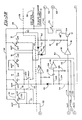
- Such a system is illustrated schematically in Figure 1 and includes a multi-position wiper control switch 10, which is somewhat different for standard and pulse-wipe systems, but including a connector 11, wiring harness 12 with voltage supply and ground illustrated at 14 which are identical for both systems.
- the wiper/washer motor assembly illustrated at 16, which includes the blade parking mechanism and other linkages, are common to both systems with the exception that each employs a different control circuit board 18 which are somewhat different but also have common interface connectors with the wiper/washer motor assembly 16. From this it can readily be seen that the only actual differences between the standard and pulse-wipe systems are reduced to variations in the wiper control switch 10 and in circuit board 18, both of which can be replaced quite easily as the interconnects are the same. This degree of commonality or interchangeability makes it relatively simple for the manufacturer to provide both systems in any vehicle made and makes it relatively simple for one to upgrade from the standard to a pulse-wipe system by retrofit at the automobile dealer.
- Another object of the present invention is to provide a means of easily integrating a moisture-sensitive wiper control system into a class of vehicles using original equipment windshield wiper control systems manufactured by General Motors Corporation.
- Still another object of the present invention is to provide a means of easily integrating a moisture-sensitive wiper control system into a class of vehicles in a manner which uses the original equipment vehicle wiring harness and plugs into existing connectors.
- Yet another object of the present invention is to provide a means of easily integrating a moisture-sensitive wiper control system into a class of vehicles in a manner which does not interfere with the operation of the standard or pulse-wipe systems already installed.
- a further object of the present invention is to provide a means of easily integrating a moisture-sensitive wiper control system into a class of vehicles in a manner which does not interfere with the operation of the original equipment wiper control system in the manual modes even if the computer of the moisture-sensitive system should cease to function for any reason.
- an automatic moisture-sensitive wiper control system which uses compatible components and the same electrical configuration of wiper control switch as that of the system with which it is designed to be integrated, namely, the General Motors pulse-wipe system.
- the moisture-sensitive wiper control unit connects to existing connectors. Operation of the system in the manual modes of OFF, LOW, HIGH AND MIST is essentially unaffected by the presence of the moisture-sensitive control unit.
- the automatic moisture-sensitive mode of operation is designed to replace the intermittent DELAY or pulse operating range in the wiper control switch which can be synonymous with or renamed "AUTO". Of course, it is not necessary to modify the switch in any way for operable installation into an existing vehicle.
- the system further can be equipped with an adjustable sensitivity based on the existing pulse rheostat or delay circuit or variable resistor.
- the driver simply moves the control switch to the AUTO or DELAY position.
- the wipers will actuate once and from that point on, the wipers will actuate at the high speed, low speed or intermittently as dictated by the moisture conditions.
- the adjustment range within the AUTO position will control the sensitivity of the system to moisture on the windshield.
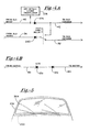
- the wipers are designed to stop at an inter-wipe position, which situates them on the windshield just below the driver's field of view but above the concealed or parked position which is below the hood for many models. This alerts the driver that the wipers are operating in the automatic or moisture-sensitive control mode rather than in the off mode. Turning off the ignition will leave the wiper position unaffected; and turning on the ignition with the wiper switch in the DELAY or AUTO position will initiate a single actuation of the wiper, returning the operation to the moisture-sensitive mode.
- the automatic moisture-sensitive wiper control system connects to existing wiring connectors in the previously-designed wiper control system. While the illustrative embodiment is specifically directed to a combination with the pulse-wipe system associated with vehicles manufactured by General Motors Corporation, it will be appreciated that the system is adaptable by those skilled in the art to other similarly situated systems, and the preferred embodiment is presented by way of illustration rather than limitation.
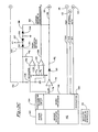
- FIG. 2 depicts a schematic block diagram of the moisture-sensitive control unit integrated into the existing pulse-wipe control system. It shows a moisture-sensitive control unit 20 which connects to a windshield-mounted moisture sensor 22 connected to the wiring harness 12 and existing wiper/washer motor assembly 16.
- the wiper control switch 24 may be the same or involve a slight modification of the wiper control switch 10, and the control circuit board 18 is the same as the circuit board of Figure 1.
- the ground system 26 includes an additional connected ground wire not used in the original ground 14.
- Figure 3D separated by broken line 30 and the part of Figure 3B above the broken line 28 represent components of the existing vehicle wiring harness and pulse wipe system
- Figure 3C together with Figure 3C represent the interconnected schematic wiring for the moisture-sensitive wiper control system which can be seen to compatibly connect into the existing harness.
- the wiper selection switch 32 when the wiper selection switch 32 is in the OFF position, it connects the conductor 34 to the power supply or source of 12-volt DC through conductors 36 and 38. This allows current to flow through a blocking diode 40. In the OFF position, of course, the wipers are designed to be in the PARK position, illustrated as 200 on Figure 5.
- the system further includes an EXIT PARK relay coil 44 associated with conductor 42. This is a "get out of park" or EXIT PARK relay as it enables the wipers to leave the park position when it is energized.
- a mechanical cam 46 is provided in the wiper motor assembly which holds the EXIT PARK relay contacts 48 closed thereby connecting conductors 50 and 52 to conductor 34 to energize low speed winding of the wiper motor 54 at 55. This allows the motor 54 to run without the PARK relay engaged and move the wipers into the fully retracted or PARK position. The further rotation of the cam 46 allows the PARK relay contacts to reopen and disconnect the motor.
- the operation of the combined system in the OFF mode is essentially equivalent to the operation of the standard and pulse-wiper systems in the OFF mode.
- the microprocessor 56 is prevented from intervening or interfering with the function of the system in the OFF mode.
- a level translator 58 is provided which senses the voltage on the conductor 34 setting the output voltage on the AUTO line 60 low (0 volts).
- Software in the microprocessor responsive to this condition inhibits the processor from attempting to command any action form the motor, regardless of information about moisture conditions detected elsewhere by the sensor.
- both conductors 34 and 42 are energized, as is the EXIT PARK relay 44 closing PARK relay contacts 48, thereby energizing the low speed winding 55 of the motor 54 via conductors 50 and 52. This operates the windshield wipers across the windshield at low speed.
- the MIST operation is basically equivalent to LOW speed operation as long as the switch 32 is held in the MIST position.
- a mechanical spring provided in the wiper control (not shown) returns the selector to OFF upon release of the switch. In this manner, the wipers will again park after release of the switch from the momentary MIST position in accordance with the operating sequence in the OFF position.
- blocking diodes 40 and 74 are necessary for operation of the system in the moisture-sensitive mode. They prevent the back emf generated by the motor at the conductor 52 from flowing back through the switch and de-energizing the PARK relay which would prevent the wiper blades from leaving the PARK position.
- the preferred embodiment uses the relay 68 to supply current to the motor rather than direct connecting the conductor 62 from the switch to the motor.
- a direct connection would provide a current path from the high-speed winding to the park relay by way of diodes 72 and 74 and conductor 42 which would produce a situation which any current to the motor would result in the appearance of an emf, the high-speed winding which, in turn, would engage the park relay thereby disabling the ability to park the wipers.
- the relay also is considerably cheaper than a diode of sufficient power capacity to operate the motor at high speed would be, and the voltage drop associated with a diode would produce an unacceptable slowing of the high-speed operation of the wiper. This condition is not only annoying to the driver but also reduces the rate that the windshield wiper can remove water from the windshield which might compromise the safety of the vehicle.
- the relay is also used in the automatic moisture-sensitive mode as will be seen below.
- the automatic moisture-sensitive mode corresponds to the pulse or delay setting of the pulse-wipe system, and references to AUTO or DELAY refer to the automatic control mode. It involves the detection of the occurrence of rainfall as determined by the moisture sensor on the windshield.
- the moisture sensor is again represented by block 22 connected to the microprocessor 56.
- the microprocessor system or circuitry also includes a power supply 160, sensor excitation and demodulation circuitry and logic identified by the block 162, potentiometer reading circuitry 164 and various diagnostic circuit devices in logic indicated by 166. For the purposes of understanding the invention of this application, the details of operation of the moisture sensor need not be set forth.
- the microprocessor 56 detects that the wiper control has, in fact, been in the AUTO or moisture-sensing position upon receipt of the HIGH signal on input line 60. Thereafter it commands a single actuation of the wiper. This is accomplished by bringing the signal on the conductor 76 ( Figure 3C) which is normally at 5 volts down to 0 volts at the SLOW output of the microprocessor so that the invertor 78 will transform this signal to 5 volts or a high output. This results in a potential through diode 80 and resistor 82 and continuing on line 84 in the moisture-sensitive control unit. Current flows through resistor 86, quickly charging a capacitor 90.
- Transistor 92 is turned on and, in turn, energizes relay 94 thereby closing contacts 96 and re-energizing the conductor 34 beyond diode 40.
- the EXIT PARK relay 44 contacts 48 are closed thereby allowing the wiper blade to begin to traverse the windshield.
- the resistor values are selected such that the timing circuit 98, which could operate the washer motor 100 via relay 102 with contacts 104 and cam switch 106, is not energized in the AUTO MODE.
- the appearance of a 12-volt voltage on conductor 34 below diode 40 produces a corresponding voltage on line 108 which causes the output of the level translator 110 on the STOPPED line 112 to go low (to 0 volts).
- the signal on line 112 informs the algorithms within the microprocessor that the wiper motor is in fact operating. This feedback may also provide useful diagnostic information inasmuch as were the STOPPED line never to go low, the algorithms in the microprocessor preferably set the diagnostics to indicate that a hardware error had occurred.
- the microprocessor When the feedback signal on the STOPPED line 112 indicating that the wipe cycle is under way is received by the microprocessor, it removes the wipe command. By this time, however, the wiper is well up on the windshield and a cam (not shown) in the timing circuit 98 continues to hold the engaged relay 94 keeping the relay contacts 96 closed until the wiper reaches the end of the wipe cycle. At this point, the cam of the timing circuit releases the contacts of relay 94, and the potential on the conductor 34 to the motor assembly drops to zero. This, in turn, causes the motor to stop and the level translator 110 to bring the signal on the STOPPED line 112 to high (5 volts). The microprocessor then uses this information to precisely set the dwell time between wipes, thereby allowing the wiper blades to remain in the inter-wipe position as illustrated at 202 in Figure 5.
- the microprocessor will repeat the above-described single actuation at intervals several seconds apart depending on the intensity of the precipitation. Should the amount of rainfall justify actuation of the wipers at a steady slow speed without pauses between wipes, the microprocessor will simply continue to hold the SLOW line 76 low. In this manner, at the end of each wipe cycle, the capacitor 90 will discharge and recharge rapidly and the cycle will repeat. This causes a delay of but a few milliseconds between wipes which is not perceptible to observers so that the wipers appear to run at a continuous rate of speed. While not objectionable, this pause may be eliminated by incorporating an additional resistor in the motor assembly in series with capacitor 90 on conductor 88. For one motor, a value of 270 ohms produced smooth operation without pause between travels of the wiper across the windshield.
- the detection of heavy rainfall by the windshield sensor will cause the unit to operate the wipers at HIGH speed. This is based on algorithms within the microprocessor which dictate that this is necessary when the input from the windshield sensor is above a certain preset threshold value.
- the microprocessor 56 sets the potential on FAST line 114 to a low state (0 volts). This signal is inverted by level translator 116 and the signal, after passing through resistor 118, turns on transistor 64 to energize relay 68 and close contacts 70 causing the full 12-volt potential to be applied to the high speed motor winding 71 via conductor 63.
- the conductor 42 is energized by way of diode 74 thereby energizing the relay 44 and engaging the contacts 48 releasing the wipers from the PARK position.
- the blocking diodes 40 and 74 make it possible for the motor to run at HIGH speed with the switch in the AUTO or moisture-sensitive position. They are necessary because when the motor is powered by way of the HIGH speed winding, it develops a rather large back electromotive force of up to 20 volts on the LOW speed winding, which is present on conductor 52. During portions of the wiping cycle, a cam (not shown) in the timing circuit 98 closes the contacts 96 of the relay 94 thereby applying this large amount of back emf to the conductor 42.
- the blocking diode 40 is also necessary in order for the microprocessor to receive accurate information pertaining to the fact that the switch is in the AUTO position. Without the diode 40, all of the conductor 34 would be at a high potential any time the motor was running. There would be no way of knowing that the user had, for example, selected manual LOW speed when the microprocessor was selecting HIGH speed.
- the addition of diode 40 allows the processor to have a single input AUTO that reliably informs the microprocessor connected algorithms that the user has selected the moisture-sensitive mode of operation.
- the system has been designed so that the slow command is removed only while the wipe cam 93 is in control. This is done by immediately sensing a slowing down of the wipers upon removal of the slow command on conductor 76. This rapid detection of motor slowing is aided by a differentiator circuit including serial resistor 120 and capacitor 122 in parallel with resistors 124 and resistor to ground 126.
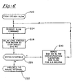
- FIG. 6 An algorithm which can be used with this system to prevent the wiper-error condition is illustrated in the schematic logic diagram of Figure 6 which operates to change the mode of operation from steady slow at 220 to intermittent wiping at 222 via the logic loop including blocks 224, 226, 228 and 230. Note that if the motor has not stopped at 228 after the 200 millisecond circuit delay at 226, the possibility of the wiper being stuck in the error position has passed and it can safely proceed to the desired pause interval at 222. If, in fact, the motor has stopped at 228, it will be restarted at 230 for 0.5 second which is plenty of time to return it to the inter-wipe position for the pause cycle at 222.
- the potentiometer 130 ( Figure 3B) associated with the delay setting on the pulse-wipe control switch which corresponds to the DELAY auto mode for the moisture-sensitive control may conveniently be used as a sensitivity adjustment setting for the moisture-sensing mode control.
- a sensitivity potentiometer reader be provided that is able to produce a value in software that corresponds linearly to the mechanical position of the sensitivity adjustment control.
- this reading of the potentiometer position should be unaffected by supply voltage or ambient temperature, and should provide good resolution of small differences in potentiometer settings.
- a ratiometric sensitivity reader circuit which generates a value corresponding to the sensitivity potentiometer setting in conjunction with resistor 131 on lines 132 and 133 that is inherently linear.
- the system includes a timing capacitor c t , a pair of resistors R a and R b and a comparator 134 on the charging circuit which gives an output on line 136.
- a discharge circuit is provided that includes a maximum discharge signal input 138, comparator 140 and resistor 142 connected to common line 132 which is, of course, in series with the potentiometer 130.
- Vcap V+ (1 exp(-t/Rpot*C t )) where Rpot equals the potentiometer setting and t is time in seconds.
- the microprocessor Conversely, after the microprocessor measures the time for Vcap to reach Vth, the microprocessor sets the DISCHARGE signal on conductor 138 high which, in turn, causes the open collector of comparator 140 to discharge c t . The microprocessor delays a sufficient time for this to happen and then restarts the charging cycle. In this manner, the system of sensitivity potentiometer, sensitivity reader circuit and microprocessor, in effect, forms an oscillator that continuously reads the setting of the sensitivity control and applies it to control the moisture-sensitive wiper control system.
- the conductor 132 from the switch in addition to controlling the sensitivity of the system, is connected directly to the input voltage on line 36 via conductor 151 when the user presses the WASH button 150.
- This manual function like other manual functions associated with the pulse-wipe system, again is performed without any intervention by the microprocessor.
- the microprocessor detects the wash condition by noting that the DISCHARGE line 138 can no longer cause the charge line 136 to go low.
- zener diode 156 together with diode 152, resistors 157 and 158, allow the sensitivity reader to remain unaffected by the circuit below a fairly high Vcap (i.e., about 5.4 volts).
- An alternative circuit shown in Figure 4B uses a 4.7 V zener diode 170 and resistor 172. The values of the circuit elements are selected so that this condition does not occur unless the user, in fact, presses the WASH button 150. In addition, it can be seen that the SLOW command generator also is not affected.
- the embodiment that has been described operates in a manner such that the wipers are parked in the INTER-WIPE position rather than the PARK position anytime that the control knob is in the DELAY or AUTO position. This avoids potential safety hazards associated with the possibility that the concealed wiper blades would traverse the windshield suddenly upon the detection of moisture rather than only in response to some conscious manual manipulation of the switch.
- the system can be implemented by providing a separate arming button.
- the arming button would function only when the switch is in the OFF mode and would initiate the single swipe repositioning sequence in which the wiper control unit would actuate the wipers once leaving the wipers in the INTER-WIPE position during subsequent operation of the system in the AUTO mode. In this manner, operating the arming button would have the same effect as putting the system into the AUTO mode without that button.
- An additional timing circuit or program in the microprocessor could be used to produce a signal to shut the system off and return the wipers to the fully parked position after the passage of a pre-determined amount of time, say 15 minutes, in which no rain is detected.
- the moisture-sensitive mode associated with the arming button would preserve the function of the delay or sensitivity adjustment involving the potentiometer and existing software.
- an indicator could be used to display the ARMED status of the system.
- the microprocessor leaves the EXIT PARK relay de-energized for operation in all manual modes.
- the DELAY or AUTO mode of the wiper switch is detected by the level translator 58, and the OFF DETECT level translator 276 looks for low input to signify that the wiper switch is still in the OFF position.
- the microprocessor pulls in the EXIT PARK relay. From this point, operation is similar to that previously described in the preferred embodiment of the interface. After about 15 minutes without sensed moisture, the microprocessor will disengage the EXIT PARK relay and the wipers will park, shutting down the system.
- the entire system involved with the automatic moisture-sensitive windshield wiper control in accordance with the invention can be integrated with the existing pulse-wipe windshield wiper control by simple connections integrating it with the existing wire harness of the pulse-wipe control without the need to change any electrical elements in that system.
- the systems are entirely compatible and the retrofit requires the making of only a few electrical and mechanical connections. This includes the use of ground wire 159 as a common ground connection.
Landscapes
- Engineering & Computer Science (AREA)
- Automation & Control Theory (AREA)
- Mechanical Engineering (AREA)
- Investigating Or Analyzing Materials By The Use Of Electric Means (AREA)
- Control Of Direct Current Motors (AREA)
- Investigating Or Analyzing Materials By The Use Of Fluid Adsorption Or Reactions (AREA)
- Control Of Electric Motors In General (AREA)
- Massaging Devices (AREA)
- Discharging, Photosensitive Material Shape In Electrophotography (AREA)
- Nonmetallic Welding Materials (AREA)
- Control Of Non-Electrical Variables (AREA)
- Electronic Switches (AREA)
- Air Bags (AREA)
Claims (13)
- Integriertes manuelles/automatisches Windschutzscheibenwischer-Steuersystem, das ein automatisches, Feuchtigkeit erfühlendes Wischer-Steuersystem (20) enthält, welches mit einem Wischer-Steuersystem der ursprünglich vorhandenen Ausstattung nachgerüstet werden kann, umfassend: ein Wischer-Steuersystem der ursprünglich vorhandenen Ausstattung enthaltend
einen Multipositionsschalter mit einem manuell einstellbaren variablen Widerstand (130), der mit einer ursprünglichen Ausstattung für einen Impuls/Wisch-Modus verbunden ist,
einen Wischersatz mit einem oder mehreren, Wischerblätter aufweisenden Windschutzscheibenwischern,
einen Wischer-Antriebsmotor (54), der zum Antreiben des Wischersatzes mechanisch geschaltet wird und einen Blattparkmechanismus enthält,
welcher derart eingerichtet ist, dass er sämtliche Blätter dazu veranlasst zu parken, wenn der Multipositionsschalter sich in der AUS-Position befindet, und sämtliche Blätter aus der Parkierung löst, wenn der Wischer-Antriebsmotor sich in einer EIN-Position befindet,
wobei der Multipositionsschalter (32) zum Betreiben des Wischer-Antriebsmotors (54) an einer oder mehreren manuell einstellbaren EIN-Laufgeschwindigkeitspositionen eingerichtet ist sowie eine AUS-Position aufweist,
eines Kabelbaum (12) mit einer Vielzahl von Leitern, um den Wischer-Antriebsmotor, den Multipositionsschalter und eine Gleichstromquelle elektrisch miteinander zu verbinden,
wobei der Kabelbaum des weiteren Impuls/Wisch-Leiter enthält, die derart ausgestaltet sind, dass sie einen wahlweisen Betrieb des WischerMotors in einem intermittierenden IMPULS/WISCH-Modus erlauben,
Schaltungselemente, welche dem Wischer-Steuersystem der ursprünglichen Ausstattung zugeordnet sind; und
ein auf erfühlte Feuchtigkeit ansprechendes, automatisches Wischer-Steuersystem, das elektrisch direkt in den Kabelbaum zwischen der Multipositionsschaltereinrichtung und dem Antriebsmotor, der den Blattparkmechanismus enthält, geschaltet ist,
wobei das feuchtigkeitsempfindliche, automatische Wischer-Steuersystem eine Schnittstellenschaltungselementeinrichtung einschließt der Art, dass es den normalen Betrieb des Wischer-Steuersystems der ursprünglichen Ausstattung in allen anderen Modi als dem IMPULS/WISCH-Modus nicht stört, und weiterhin aufweisend eine Empfindlichkeitsjustiersteuereinrichtung zum Justieren der Empfindlichkeit des Feuchtigkeit erfühlenden Systems mittels des manuell einstellbaren variablen Widerstandes. - Vorrichtung nach Anspruch 1, bei der die Feuchtigkeit erfühlende, automatische Wischer-Steuerung eine Mikroprozessor-Steuerschaltung (56) einschließt und das Schnittstellenschaltungselement eine Einrichtung enthält, um zu verhindern, dass der Mikroprozessor den Betrieb des Wischer-Steuersystems der ursprünglichen Ausstattung in einem anderen Modus als dem IMPULS/WISCH-Modus stört.
- Vorrichtung nach Anspruch 2, bei der das Schnittstellenschaltungselement des weiteren eine Pegeltranslatoreneinrichtung zum Steuern von Mikroprozessor-Steuereingangssignalen während des manuellen Betriebes der Wischersysteme der ursprünglichen Ausstattung und Blockierdiodeneinrichtungen (40, 74) zum Steuern von Eingangsspannung zur Pegeltranslatoreneinrichtung (116) und zum Unterstützen von EMK aus dem Motor einschließt.
- Vorrichtung nach Anspruch 2 oder 3, bei der die Schnittstellenschaltungseinrichtung des weiteren ein Relais (94) einschließt, das den Wischermotor im Hochgeschwindigkeitsbetrieb schalten kann, welcher mit dem Multipositionsschalter betriebsschlüssig verbunden ist, der ein manuelles Übersteuern des Feuchtigkeit erfühlenden Windschutzscheibenwischer-Steuersystems erlaubt.
- Vorrichtung nach einem der vorhergehenden Ansprüche, bei der die Multipositionsschaltereinrichtung zum Betreiben des Wischerantriebsmotors mit einer Vielzahl von manuell einstellbaren EIN-Laufgeschwindigkeitsmodi, einem NEBEL-Modus, einem AUS-Modus und einem wahlweisen IMPULS/WISCH-Automatikmodus eingerichtet ist; bei der das Feuchtigkeit erfühlende, automatische Wischer-Steuersystem eine Mikroporzessor-Steuereinrichtung (56) einschließt, die auf eine Art und Weise elektrisch in den Kabelbaum (12) zwischen der Multipositionsschaltereinrichtung (32) und der Wischerantriebsmotoreinrichtung (54) geschaltet ist, die keine Änderung bei den Kabelbaumelementen oder den vorhandenen Schaltungselementen erforderlich macht; bei der das Feuchtigkeit erfühlende, automatische Steuersystem derart geschaltet ist, dass es den wahlweisen Impuls/Wisch-Modus direkt ersetzt, und bei der das Feuchtigkeit erfühlende, automatische Wischer-Steuersystem (20, 21) eine Schnittstellenschaltungselementeinrichtung enthält der Art, dass das Feuchtigkeit erfühlende Steuersystem einschließlich der Mikroprozessoreinrichtung den vorschriftsmäßigen Betrieb des Wischer-Steuersystems der ursprünglichen Ausstattung in allen anderen Modi als dem IMPULS/WISCH-Modus nicht stört.
- Vorrichtung nach Anspruch 5, bei der die Schnittstellenschaltungselementeinrichtung des weiteren eine Pegeltranslatoreneinrichtung zum Steuern von Mikroprozessor-Steuereingangssignalen während des manuellen Betriebes der Wischersysteme der ursprünglichen Ausstattung und Blockierdiodeneinrichtungen zum Steuern von Spannungseingang zur Pegeltranslatoreneinrichtung und zum Unterstützen von EMK aus dem Motor einschließt.
- Vorrichtung nach Anspruch 6, weiterhin umfassend eine Einrichtung zum Verhindern eines Blockierens der Wischer auf der Windschutzscheibe in einer Fehlerposition, wenn im FEUCHTIGKEIT-ER-FÜHLUNGS-Modus gearbeitet wird.
- Vorrichtung nach Anspruch 7, bei der die Einrichtung zum Verhindern eines Blockierens der Wischer in der Fehlerposition einen Wischermotor-Steueralgorithmus umfasst.
- Vorrichtung nach Anspruch 7, bei der die Einrichtung zum Verhindern eines Blockierens der Wischer in der Fehlerposition einen Kontaktschließnocken und eine Differenzierschaltung umfasst, die das Stoppen des Motors ermittelt.
- Vorrichtung nach Anspruch 9, bei der die Einrichtung zum Justieren der Empfindlichkeit des Feuchtigkeit erfühlenden Systems weiterhin eine Empfindlichkeitsleseschaltung aufweist, mit der der Mikroprozessor die Einstellung des variablen Widerstandes ständig überwacht und diese zum Steuern der feuchtigkeitsempfindlichen Wischer-Steuersysteme verwendet.
- Vorrichtung nach Anspruch 10, bei der die Einrichtung zum Justieren der Empfindlichkeit des Feuchtigkeit erfühlenden Systems eine Linearisiereinrichtung einschließt, die der Empfindlichkeitsleseschaltung zugeordnet ist, welche einen Wert in Software erzeugt, der linear der mechanischen Position der Empfindlichkeitsjustierungssteuerung entspricht.
- Vorrichtung nach Anspruch 7, einschließend eine Einrichtung zum Bewegen der Blätter aus einer verborgenen in eine sichtbare Position, wenn das feuchtigkeitsempfindliche System aktiviert wird.
- Vorrichtung nach Anspruch 12, einschließend eine separate Auslösesteuerung, um die Wischer nachzujustieren und um anzuzeigen, dass das feuchtigkeitsempfindliche Steuersystem aktiviert worden ist.
Applications Claiming Priority (3)
| Application Number | Priority Date | Filing Date | Title |
|---|---|---|---|
| US07/845,395 US5239244A (en) | 1992-03-03 | 1992-03-03 | Vehicle interface for moisture-sensitive wiper control |
| US845395 | 1992-03-03 | ||
| PCT/US1993/002348 WO1993017897A1 (en) | 1992-03-03 | 1993-03-03 | Vehicle interface for moisture-sensitive wiper control |
Publications (4)
| Publication Number | Publication Date |
|---|---|
| EP0598862A1 EP0598862A1 (de) | 1994-06-01 |
| EP0598862A4 EP0598862A4 (de) | 1994-10-19 |
| EP0598862B1 EP0598862B1 (de) | 1998-07-29 |
| EP0598862B2 true EP0598862B2 (de) | 2003-04-02 |
Family
ID=25295140
Family Applications (1)
| Application Number | Title | Priority Date | Filing Date |
|---|---|---|---|
| EP93908346A Expired - Lifetime EP0598862B2 (de) | 1992-03-03 | 1993-03-03 | Fahrzeugschnittstelle für feuchtigkeitsempflindliche wischersteuerung |
Country Status (14)
| Country | Link |
|---|---|
| US (1) | US5239244A (de) |
| EP (1) | EP0598862B2 (de) |
| JP (1) | JP3428644B2 (de) |
| KR (1) | KR100262775B1 (de) |
| AT (1) | ATE168950T1 (de) |
| AU (1) | AU662821B2 (de) |
| BR (1) | BR9305421A (de) |
| CA (1) | CA2109209C (de) |
| DE (1) | DE69320001T3 (de) |
| ES (1) | ES2121081T5 (de) |
| FI (1) | FI934855A0 (de) |
| TW (1) | TW277035B (de) |
| WO (1) | WO1993017897A1 (de) |
| ZA (1) | ZA931480B (de) |
Families Citing this family (35)
| Publication number | Priority date | Publication date | Assignee | Title |
|---|---|---|---|---|
| DE4112847A1 (de) * | 1991-04-19 | 1992-10-22 | Bosch Gmbh Robert | Vorrichtung zum betreiben eines regendetektors |
| US5404085A (en) * | 1992-07-10 | 1995-04-04 | Rosemount Aerospace, Inc. | Multifunction aircraft windscreen wiper control system |
| US5453670A (en) * | 1994-01-03 | 1995-09-26 | Schaefer; Eric G. | Method of controlling a windshield wiper system |
| US5556493A (en) * | 1995-01-13 | 1996-09-17 | Libbey-Owens-Ford Co. | Mounting an optical moisture sensor on a windshield using a vacuum chamber device |
| DE4424028C2 (de) * | 1994-07-11 | 1997-07-03 | Vdo Schindling | Abrißerkennung für einen Regensensor |
| EP0778807A1 (de) * | 1994-09-13 | 1997-06-18 | Itt Automotive Electrical Systems, Inc. | Allgemeine steuerschaltung für scheibenwischer |
| US5493190A (en) * | 1994-09-30 | 1996-02-20 | Itt Automotive Electrical Systems, Inc. | Windshield wiper auto-delay control interface |
| US5704038A (en) * | 1994-09-30 | 1997-12-30 | Itt Automotive Electrical Systems, Inc. | Power-on-reset and watchdog circuit and method |
| DE4445107A1 (de) * | 1994-12-19 | 1996-06-20 | Bosch Gmbh Robert | Schaltungsanordnung, insbesondere für eine Wischanlage für Kraftfahrzeugscheiben |
| US5568027A (en) * | 1995-05-19 | 1996-10-22 | Libbey-Owens-Ford Co. | Smooth rain-responsive wiper control |
| DE19519485C2 (de) * | 1995-05-27 | 1998-01-29 | Bosch Gmbh Robert | Vorrichtung zum Betreiben eines Scheibenwischers |
| US6242876B1 (en) | 1995-06-07 | 2001-06-05 | Valeo Electrical Systems, Inc. | Intermittent windshield wiper controller |
| DE19604544A1 (de) * | 1996-02-08 | 1997-08-14 | Bosch Gmbh Robert | Anschluß eines Regensensor-Steuergerätes an den Fahrzeugkabelbaum |
| US6144017A (en) * | 1997-03-19 | 2000-11-07 | Libbey-Owens-Ford Co. | Condensation control system for heated insulating glass units |
| DE19742657A1 (de) * | 1997-09-26 | 1999-04-01 | Bosch Gmbh Robert | Wischvorrichtung |
| US5898183A (en) | 1997-10-16 | 1999-04-27 | Libbey-Owens-Ford Co. | Compact moisture sensor with efficient high obliquity optics |
| US6020704A (en) * | 1997-12-02 | 2000-02-01 | Valeo Electrical Systems, Inc. | Windscreen sensing and wiper control system |
| DE19755441A1 (de) * | 1997-12-13 | 1999-06-17 | Itt Mfg Enterprises Inc | Empfindlichkeitseinstellung für Regensensoren ohne zusätzliche Schalt- oder Stellglieder |
| US6144906A (en) * | 1998-08-06 | 2000-11-07 | Valeo Electrical Systems, Inc. | Adaptive pulse control |
| US5990647A (en) * | 1998-10-29 | 1999-11-23 | Kelsey-Hayes Co. | Embedded self-test for rain sensors |
| US6232603B1 (en) | 1998-10-29 | 2001-05-15 | Kelsey-Hayes Co. | Rain sensor operation on solar reflective glass |
| US6069461A (en) * | 1998-11-16 | 2000-05-30 | Ford Global Technologies, Inc. | Digital or resistorless interval wiper switch and system |
| US6078056A (en) | 1998-12-30 | 2000-06-20 | Libbey-Owens-Ford Co. | Moisture sensor with autobalance control |
| US6262407B1 (en) | 1998-12-31 | 2001-07-17 | Libbey-Owens-Ford Co. | Moisture sensor with automatic emitter intensity control |
| US6091065A (en) * | 1998-12-31 | 2000-07-18 | Libbey-Owens-Ford Co. | Moisture sensor with digital signal processing filtering |
| KR20050006757A (ko) * | 2003-07-10 | 2005-01-17 | 현대자동차주식회사 | 우적 감응형 윈드 시일드 와이퍼 시스템 |
| KR100508447B1 (ko) * | 2003-09-03 | 2005-08-17 | 기아자동차주식회사 | 차량의 우적 감지형 와이퍼 장치 및 그 제어 방법 |
| KR100727353B1 (ko) * | 2006-06-09 | 2007-06-13 | 현대자동차주식회사 | 자동빗물감지 와이퍼 장치 |
| WO2008084577A1 (ja) * | 2007-01-10 | 2008-07-17 | Sumitomo Wiring Systems, Ltd. | ワイパー制御回路 |
| KR20090103526A (ko) * | 2008-03-28 | 2009-10-01 | 주식회사 현대오토넷 | 와이퍼 위치 제어장치 및 그 방법 |
| JP2012510399A (ja) * | 2008-12-02 | 2012-05-10 | ピルキントン グループ リミテッド | ウインドシールドワイパ制御システム |
| CN102632863A (zh) * | 2012-03-27 | 2012-08-15 | 奇瑞汽车股份有限公司 | 一种汽车雨刮系统及其控制方法 |
| KR101490952B1 (ko) * | 2013-12-23 | 2015-02-09 | 현대자동차 주식회사 | 회전체의 위치를 파악하는 장치 및 이를 이용한 와이퍼 작동 장치 |
| CN109606319A (zh) * | 2018-12-08 | 2019-04-12 | 郑州工业应用技术学院 | 一种刮雨器控制装置 |
| US20240175490A1 (en) * | 2022-11-24 | 2024-05-30 | Jen-chih Liu | Electrical control apparatus of internal speed change device of wheel hub for gear switching |
Citations (3)
| Publication number | Priority date | Publication date | Assignee | Title |
|---|---|---|---|---|
| DE1580760A1 (de) † | 1966-10-28 | 1971-01-14 | Rau Swf Autozubehoer | Elektrische Schaltanordnung |
| DE3022442C2 (de) † | 1980-06-14 | 1989-03-16 | Swf Auto-Electric Gmbh, 7120 Bietigheim-Bissingen, De | |
| DE3818563A1 (de) † | 1988-06-01 | 1989-12-07 | Swf Auto Electric Gmbh | Elektromotor zum antrieb von scheibenwischern an kraftfahrzeugen |
Family Cites Families (22)
| Publication number | Priority date | Publication date | Assignee | Title |
|---|---|---|---|---|
| US4317073A (en) * | 1977-02-03 | 1982-02-23 | Henry Blaszkowski | Windshield wiper control system |
| EP0009414B1 (de) * | 1978-09-25 | 1984-04-25 | Raymond James Noack | Vorrichtung und Verfahren zum Steuern der Scheibenwischer- und Scheibenwaschgeräte eines Fahrzeugs |
| DK146959C (da) * | 1981-12-08 | 1984-08-06 | Boeegh Petersen Allan | Viskerrobot med foeler |
| IT1156372B (it) * | 1982-06-22 | 1987-02-04 | Fiat Auto Spa | Dispositivo di regolazione automatica della frequenza di attivazione di un tergicristallo per veicoli |
| JPS59137842A (ja) * | 1983-01-28 | 1984-08-08 | Jidosha Denki Kogyo Co Ltd | 雨滴検出器の振動板保持構造 |
| US4554493A (en) * | 1984-02-29 | 1985-11-19 | Armstrong Howard L | Automated windshield wiper system |
| JPS61169850U (de) * | 1985-04-11 | 1986-10-21 | ||
| US4620141A (en) * | 1985-07-03 | 1986-10-28 | Vericom Corp. | Rain-controlled windshield wipers |
| JPS62172662U (de) * | 1986-04-23 | 1987-11-02 | ||
| DE3619587A1 (de) * | 1986-06-11 | 1987-12-17 | Swf Auto Electric Gmbh | Schalter zur ansteuerung eines elektromotors einer wischeranlage |
| US4867561A (en) * | 1986-08-22 | 1989-09-19 | Nippondenso Co., Ltd. | Apparatus for optically detecting an extraneous matter on a translucent shield |
| US4705998A (en) * | 1987-02-09 | 1987-11-10 | Steven Alpert | Automatic window wiper control |
| WO1988006989A1 (fr) * | 1987-03-17 | 1988-09-22 | Doduco Kg Dr. Eugen Dürrwächter | Procede et commutateur intermittent ayant un agencement de circuit de commande de l'intervalle d'essuyage d'essuie-glaces de vehicules |
| US4798956A (en) * | 1987-07-15 | 1989-01-17 | Hochstein Peter A | Electro-optical windshield moisture sensing |
| US4797605A (en) * | 1987-08-21 | 1989-01-10 | Delco Electronics Corporation | Moisture sensor and method of fabrication thereof |
| US4805070A (en) * | 1987-10-22 | 1989-02-14 | Ppg Industries, Inc. | Capacitive coupled moisture sensor |
| US4859867A (en) * | 1988-04-19 | 1989-08-22 | Donnelly Corporation | Windshield moisture sensing control circuit |
| US4893506A (en) * | 1988-07-14 | 1990-01-16 | Industrial Technology Research Institute | Method for estimating rainfall and a sensing device therefor |
| US4859919A (en) * | 1988-08-29 | 1989-08-22 | General Motors Corporation | Window wiper control for vehicle |
| DE3941905A1 (de) * | 1988-12-19 | 1990-06-21 | Fujitsu Ten Ltd | Scheibenwischersteuervorrichtung |
| DE3922484A1 (de) * | 1989-07-08 | 1991-01-17 | Duerrwaechter E Dr Doduco | Verfahren und intervallschalter mit einer schaltungsanordnung zur steuerung des wischintervalls von scheibenwischern in fahrzeugen |
| US5059877A (en) * | 1989-12-22 | 1991-10-22 | Libbey-Owens-Ford Co. | Rain responsive windshield wiper control |
-
1992
- 1992-03-03 US US07/845,395 patent/US5239244A/en not_active Expired - Lifetime
-
1993
- 1993-02-22 TW TW082101236A patent/TW277035B/zh active
- 1993-03-02 ZA ZA931480A patent/ZA931480B/xx unknown
- 1993-03-03 AT AT93908346T patent/ATE168950T1/de not_active IP Right Cessation
- 1993-03-03 JP JP51604893A patent/JP3428644B2/ja not_active Expired - Fee Related
- 1993-03-03 AU AU39197/93A patent/AU662821B2/en not_active Ceased
- 1993-03-03 ES ES93908346T patent/ES2121081T5/es not_active Expired - Lifetime
- 1993-03-03 FI FI934855A patent/FI934855A0/fi unknown
- 1993-03-03 BR BR9305421A patent/BR9305421A/pt not_active IP Right Cessation
- 1993-03-03 CA CA002109209A patent/CA2109209C/en not_active Expired - Fee Related
- 1993-03-03 EP EP93908346A patent/EP0598862B2/de not_active Expired - Lifetime
- 1993-03-03 KR KR1019930703309A patent/KR100262775B1/ko not_active Expired - Fee Related
- 1993-03-03 WO PCT/US1993/002348 patent/WO1993017897A1/en not_active Ceased
- 1993-03-03 DE DE69320001T patent/DE69320001T3/de not_active Expired - Fee Related
Patent Citations (3)
| Publication number | Priority date | Publication date | Assignee | Title |
|---|---|---|---|---|
| DE1580760A1 (de) † | 1966-10-28 | 1971-01-14 | Rau Swf Autozubehoer | Elektrische Schaltanordnung |
| DE3022442C2 (de) † | 1980-06-14 | 1989-03-16 | Swf Auto-Electric Gmbh, 7120 Bietigheim-Bissingen, De | |
| DE3818563A1 (de) † | 1988-06-01 | 1989-12-07 | Swf Auto Electric Gmbh | Elektromotor zum antrieb von scheibenwischern an kraftfahrzeugen |
Also Published As
| Publication number | Publication date |
|---|---|
| BR9305421A (pt) | 1998-06-23 |
| DE69320001T2 (de) | 1999-04-01 |
| EP0598862B1 (de) | 1998-07-29 |
| JPH06507593A (ja) | 1994-09-01 |
| ES2121081T5 (es) | 2003-11-01 |
| WO1993017897A1 (en) | 1993-09-16 |
| FI934855A7 (fi) | 1993-11-03 |
| DE69320001D1 (de) | 1998-09-03 |
| DE69320001T3 (de) | 2004-01-22 |
| EP0598862A1 (de) | 1994-06-01 |
| EP0598862A4 (de) | 1994-10-19 |
| FI934855L (fi) | 1993-11-03 |
| KR100262775B1 (ko) | 2000-08-01 |
| ZA931480B (en) | 1993-09-23 |
| FI934855A0 (fi) | 1993-11-03 |
| ES2121081T3 (es) | 1998-11-16 |
| TW277035B (de) | 1996-06-01 |
| CA2109209C (en) | 2003-05-13 |
| ATE168950T1 (de) | 1998-08-15 |
| AU662821B2 (en) | 1995-09-14 |
| JP3428644B2 (ja) | 2003-07-22 |
| US5239244A (en) | 1993-08-24 |
| AU3919793A (en) | 1993-10-05 |
| CA2109209A1 (en) | 1993-09-04 |
Similar Documents
| Publication | Publication Date | Title |
|---|---|---|
| EP0598862B2 (de) | Fahrzeugschnittstelle für feuchtigkeitsempflindliche wischersteuerung | |
| US5187383A (en) | Headlight actuator associated with windsheild wiper actuation having delay circuits and daylight detection | |
| US4339698A (en) | Control apparatus for windshield wiper system | |
| US4348726A (en) | Method of controlling automobile equipment and control apparatus | |
| FR2720349A1 (fr) | Procédé pour évaluer l'auto-diagnostic d'un appareil de commande dans un véhicule automobile. | |
| EP0394227A1 (de) | Selbsttätige regelung eines fensterwischers | |
| GB2049234A (en) | Windscreen wiper installation | |
| US4999550A (en) | Automatic rear wiper control | |
| EP0899172B1 (de) | Regelverfahren für Scheibenwischer | |
| US5459380A (en) | Moisture activated window closer | |
| EP0848490A1 (de) | Einstellbare Motorregelschaltung für Fensterheberantrieb | |
| US5029662A (en) | Heating elements for vehicle with remote control | |
| US3483459A (en) | Pulsed windshield wiper motor control | |
| US4286200A (en) | Universal intermittent windshield wiper circuit | |
| CN221316077U (zh) | 雨刮控制装置以及机动设备 | |
| JPH11165612A (ja) | ワイパ装置 | |
| KR100375379B1 (ko) | 자동 파킹의 기능을 갖는 자동차용 와이퍼 시스템 | |
| KR20000064844A (ko) | 와이퍼 모터를 갖는 제어장치 | |
| EP0186178B1 (de) | Verdeckte Wischeranordnung | |
| JP2582618Y2 (ja) | オートワイパ装置 | |
| KR19980043313A (ko) | 자동차 윈드실드 와이퍼 속도 자동제어장치 및 그 제어방법 | |
| KR0123965Y1 (ko) | 자동차의 뒷유리 열선 제어장치 | |
| JP2648365B2 (ja) | ワイパの制御方法 | |
| KR0173410B1 (ko) | 후시경 각도 자동 조절 장치 및 그 제어 방법 | |
| JPH0476817B2 (de) |
Legal Events
| Date | Code | Title | Description |
|---|---|---|---|
| PUAI | Public reference made under article 153(3) epc to a published international application that has entered the european phase |
Free format text: ORIGINAL CODE: 0009012 |
|
| 17P | Request for examination filed |
Effective date: 19940113 |
|
| AK | Designated contracting states |
Kind code of ref document: A1 Designated state(s): AT BE CH DE ES FR GB IT LI LU SE |
|
| A4 | Supplementary search report drawn up and despatched |
Effective date: 19940829 |
|
| AK | Designated contracting states |
Kind code of ref document: A4 Designated state(s): AT BE CH DE ES FR GB IT LI LU SE |
|
| 17Q | First examination report despatched |
Effective date: 19951026 |
|
| GRAG | Despatch of communication of intention to grant |
Free format text: ORIGINAL CODE: EPIDOS AGRA |
|
| GRAG | Despatch of communication of intention to grant |
Free format text: ORIGINAL CODE: EPIDOS AGRA |
|
| GRAH | Despatch of communication of intention to grant a patent |
Free format text: ORIGINAL CODE: EPIDOS IGRA |
|
| GRAH | Despatch of communication of intention to grant a patent |
Free format text: ORIGINAL CODE: EPIDOS IGRA |
|
| GRAA | (expected) grant |
Free format text: ORIGINAL CODE: 0009210 |
|
| AK | Designated contracting states |
Kind code of ref document: B1 Designated state(s): AT BE CH DE ES FR GB IT LI LU SE |
|
| REF | Corresponds to: |
Ref document number: 168950 Country of ref document: AT Date of ref document: 19980815 Kind code of ref document: T |
|
| REG | Reference to a national code |
Ref country code: CH Ref legal event code: EP |
|
| REF | Corresponds to: |
Ref document number: 69320001 Country of ref document: DE Date of ref document: 19980903 |
|
| REG | Reference to a national code |
Ref country code: CH Ref legal event code: NV Representative=s name: E. BLUM & CO. PATENTANWAELTE |
|
| REG | Reference to a national code |
Ref country code: ES Ref legal event code: FG2A Ref document number: 2121081 Country of ref document: ES Kind code of ref document: T3 |
|
| ET | Fr: translation filed | ||
| PGFP | Annual fee paid to national office [announced via postgrant information from national office to epo] |
Ref country code: AT Payment date: 19990219 Year of fee payment: 7 |
|
| PGFP | Annual fee paid to national office [announced via postgrant information from national office to epo] |
Ref country code: CH Payment date: 19990224 Year of fee payment: 7 |
|
| PGFP | Annual fee paid to national office [announced via postgrant information from national office to epo] |
Ref country code: LU Payment date: 19990310 Year of fee payment: 7 |
|
| PLBI | Opposition filed |
Free format text: ORIGINAL CODE: 0009260 |
|
| PLBF | Reply of patent proprietor to notice(s) of opposition |
Free format text: ORIGINAL CODE: EPIDOS OBSO |
|
| 26 | Opposition filed |
Opponent name: ROBERT BOSCH GMBH Effective date: 19990429 |
|
| PLBF | Reply of patent proprietor to notice(s) of opposition |
Free format text: ORIGINAL CODE: EPIDOS OBSO |
|
| PLBF | Reply of patent proprietor to notice(s) of opposition |
Free format text: ORIGINAL CODE: EPIDOS OBSO |
|
| PG25 | Lapsed in a contracting state [announced via postgrant information from national office to epo] |
Ref country code: LU Free format text: LAPSE BECAUSE OF NON-PAYMENT OF DUE FEES Effective date: 20000303 Ref country code: AT Free format text: LAPSE BECAUSE OF NON-PAYMENT OF DUE FEES Effective date: 20000303 |
|
| PG25 | Lapsed in a contracting state [announced via postgrant information from national office to epo] |
Ref country code: LI Free format text: LAPSE BECAUSE OF NON-PAYMENT OF DUE FEES Effective date: 20000331 Ref country code: CH Free format text: LAPSE BECAUSE OF NON-PAYMENT OF DUE FEES Effective date: 20000331 |
|
| PLAW | Interlocutory decision in opposition |
Free format text: ORIGINAL CODE: EPIDOS IDOP |
|
| APAC | Appeal dossier modified |
Free format text: ORIGINAL CODE: EPIDOS NOAPO |
|
| APAE | Appeal reference modified |
Free format text: ORIGINAL CODE: EPIDOS REFNO |
|
| REG | Reference to a national code |
Ref country code: CH Ref legal event code: PL |
|
| APAC | Appeal dossier modified |
Free format text: ORIGINAL CODE: EPIDOS NOAPO |
|
| REG | Reference to a national code |
Ref country code: GB Ref legal event code: IF02 |
|
| APAC | Appeal dossier modified |
Free format text: ORIGINAL CODE: EPIDOS NOAPO |
|
| PLAW | Interlocutory decision in opposition |
Free format text: ORIGINAL CODE: EPIDOS IDOP |
|
| PUAH | Patent maintained in amended form |
Free format text: ORIGINAL CODE: 0009272 |
|
| STAA | Information on the status of an ep patent application or granted ep patent |
Free format text: STATUS: PATENT MAINTAINED AS AMENDED |
|
| PGFP | Annual fee paid to national office [announced via postgrant information from national office to epo] |
Ref country code: SE Payment date: 20030221 Year of fee payment: 11 |
|
| 27A | Patent maintained in amended form |
Effective date: 20030402 |
|
| AK | Designated contracting states |
Designated state(s): AT BE CH DE ES FR GB IT LI LU SE |
|
| PGFP | Annual fee paid to national office [announced via postgrant information from national office to epo] |
Ref country code: ES Payment date: 20030408 Year of fee payment: 11 |
|
| REG | Reference to a national code |
Ref country code: SE Ref legal event code: RPEO |
|
| REG | Reference to a national code |
Ref country code: ES Ref legal event code: DC2A Date of ref document: 20030521 Kind code of ref document: T5 |
|
| ET3 | Fr: translation filed ** decision concerning opposition | ||
| PG25 | Lapsed in a contracting state [announced via postgrant information from national office to epo] |
Ref country code: SE Free format text: LAPSE BECAUSE OF NON-PAYMENT OF DUE FEES Effective date: 20040304 Ref country code: ES Free format text: LAPSE BECAUSE OF NON-PAYMENT OF DUE FEES Effective date: 20040304 |
|
| EUG | Se: european patent has lapsed | ||
| PGFP | Annual fee paid to national office [announced via postgrant information from national office to epo] |
Ref country code: GB Payment date: 20050223 Year of fee payment: 13 |
|
| PGFP | Annual fee paid to national office [announced via postgrant information from national office to epo] |
Ref country code: FR Payment date: 20050321 Year of fee payment: 13 |
|
| PGFP | Annual fee paid to national office [announced via postgrant information from national office to epo] |
Ref country code: BE Payment date: 20050429 Year of fee payment: 13 |
|
| PGFP | Annual fee paid to national office [announced via postgrant information from national office to epo] |
Ref country code: DE Payment date: 20050502 Year of fee payment: 13 |
|
| REG | Reference to a national code |
Ref country code: ES Ref legal event code: FD2A Effective date: 20040304 |
|
| APAH | Appeal reference modified |
Free format text: ORIGINAL CODE: EPIDOSCREFNO |
|
| PG25 | Lapsed in a contracting state [announced via postgrant information from national office to epo] |
Ref country code: GB Free format text: LAPSE BECAUSE OF NON-PAYMENT OF DUE FEES Effective date: 20060303 |
|
| PG25 | Lapsed in a contracting state [announced via postgrant information from national office to epo] |
Ref country code: BE Free format text: LAPSE BECAUSE OF NON-PAYMENT OF DUE FEES Effective date: 20060331 |
|
| PGFP | Annual fee paid to national office [announced via postgrant information from national office to epo] |
Ref country code: IT Payment date: 20060331 Year of fee payment: 14 |
|
| PG25 | Lapsed in a contracting state [announced via postgrant information from national office to epo] |
Ref country code: DE Free format text: LAPSE BECAUSE OF NON-PAYMENT OF DUE FEES Effective date: 20061003 |
|
| GBPC | Gb: european patent ceased through non-payment of renewal fee |
Effective date: 20060303 |
|
| REG | Reference to a national code |
Ref country code: FR Ref legal event code: ST Effective date: 20061130 |
|
| BERE | Be: lapsed |
Owner name: *LIBBEY-OWENS-FORD CO. Effective date: 20060331 |
|
| PG25 | Lapsed in a contracting state [announced via postgrant information from national office to epo] |
Ref country code: FR Free format text: LAPSE BECAUSE OF NON-PAYMENT OF DUE FEES Effective date: 20060331 |
|
| PG25 | Lapsed in a contracting state [announced via postgrant information from national office to epo] |
Ref country code: IT Free format text: LAPSE BECAUSE OF NON-PAYMENT OF DUE FEES Effective date: 20070303 |