EP0599037A2 - Pressformmaschine zur Herstellung von optischen Elementen und Verfahren zur Herstellung derselben - Google Patents
Pressformmaschine zur Herstellung von optischen Elementen und Verfahren zur Herstellung derselben Download PDFInfo
- Publication number
- EP0599037A2 EP0599037A2 EP93116382A EP93116382A EP0599037A2 EP 0599037 A2 EP0599037 A2 EP 0599037A2 EP 93116382 A EP93116382 A EP 93116382A EP 93116382 A EP93116382 A EP 93116382A EP 0599037 A2 EP0599037 A2 EP 0599037A2
- Authority
- EP
- European Patent Office
- Prior art keywords
- molding
- raw material
- optical
- optical raw
- mold assembly
- Prior art date
- Legal status (The legal status is an assumption and is not a legal conclusion. Google has not performed a legal analysis and makes no representation as to the accuracy of the status listed.)
- Withdrawn
Links
Images


Classifications
-
- C—CHEMISTRY; METALLURGY
- C03—GLASS; MINERAL OR SLAG WOOL
- C03B—MANUFACTURE, SHAPING, OR SUPPLEMENTARY PROCESSES
- C03B11/00—Pressing molten glass or performed glass reheated to equivalent low viscosity without blowing
- C03B11/06—Construction of plunger or mould
- C03B11/08—Construction of plunger or mould for making solid articles, e.g. lenses
-
- B—PERFORMING OPERATIONS; TRANSPORTING
- B29—WORKING OF PLASTICS; WORKING OF SUBSTANCES IN A PLASTIC STATE IN GENERAL
- B29C—SHAPING OR JOINING OF PLASTICS; SHAPING OF MATERIAL IN A PLASTIC STATE, NOT OTHERWISE PROVIDED FOR; AFTER-TREATMENT OF THE SHAPED PRODUCTS, e.g. REPAIRING
- B29C43/00—Compression moulding, i.e. applying external pressure to flow the moulding material; Apparatus therefor
- B29C43/32—Component parts, details or accessories; Auxiliary operations
- B29C43/36—Moulds for making articles of definite length, i.e. discrete articles
- B29C43/361—Moulds for making articles of definite length, i.e. discrete articles with pressing members independently movable of the parts for opening or closing the mould, e.g. movable pistons
- B29C2043/3615—Forming elements, e.g. mandrels or rams or stampers or pistons or plungers or punching devices
- B29C2043/3618—Forming elements, e.g. mandrels or rams or stampers or pistons or plungers or punching devices plurality of counteracting elements
-
- B—PERFORMING OPERATIONS; TRANSPORTING
- B29—WORKING OF PLASTICS; WORKING OF SUBSTANCES IN A PLASTIC STATE IN GENERAL
- B29C—SHAPING OR JOINING OF PLASTICS; SHAPING OF MATERIAL IN A PLASTIC STATE, NOT OTHERWISE PROVIDED FOR; AFTER-TREATMENT OF THE SHAPED PRODUCTS, e.g. REPAIRING
- B29C35/00—Heating, cooling or curing, e.g. crosslinking or vulcanising; Apparatus therefor
- B29C35/02—Heating or curing, e.g. crosslinking or vulcanizing during moulding, e.g. in a mould
- B29C35/08—Heating or curing, e.g. crosslinking or vulcanizing during moulding, e.g. in a mould by wave energy or particle radiation
- B29C35/0888—Heating or curing, e.g. crosslinking or vulcanizing during moulding, e.g. in a mould by wave energy or particle radiation using transparant moulds
-
- B—PERFORMING OPERATIONS; TRANSPORTING
- B29—WORKING OF PLASTICS; WORKING OF SUBSTANCES IN A PLASTIC STATE IN GENERAL
- B29C—SHAPING OR JOINING OF PLASTICS; SHAPING OF MATERIAL IN A PLASTIC STATE, NOT OTHERWISE PROVIDED FOR; AFTER-TREATMENT OF THE SHAPED PRODUCTS, e.g. REPAIRING
- B29C43/00—Compression moulding, i.e. applying external pressure to flow the moulding material; Apparatus therefor
- B29C43/02—Compression moulding, i.e. applying external pressure to flow the moulding material; Apparatus therefor of articles of definite length, i.e. discrete articles
- B29C43/021—Compression moulding, i.e. applying external pressure to flow the moulding material; Apparatus therefor of articles of definite length, i.e. discrete articles characterised by the shape of the surface
-
- B—PERFORMING OPERATIONS; TRANSPORTING
- B29—WORKING OF PLASTICS; WORKING OF SUBSTANCES IN A PLASTIC STATE IN GENERAL
- B29C—SHAPING OR JOINING OF PLASTICS; SHAPING OF MATERIAL IN A PLASTIC STATE, NOT OTHERWISE PROVIDED FOR; AFTER-TREATMENT OF THE SHAPED PRODUCTS, e.g. REPAIRING
- B29C43/00—Compression moulding, i.e. applying external pressure to flow the moulding material; Apparatus therefor
- B29C43/32—Component parts, details or accessories; Auxiliary operations
- B29C43/36—Moulds for making articles of definite length, i.e. discrete articles
- B29C43/361—Moulds for making articles of definite length, i.e. discrete articles with pressing members independently movable of the parts for opening or closing the mould, e.g. movable pistons
-
- B—PERFORMING OPERATIONS; TRANSPORTING
- B29—WORKING OF PLASTICS; WORKING OF SUBSTANCES IN A PLASTIC STATE IN GENERAL
- B29L—INDEXING SCHEME ASSOCIATED WITH SUBCLASS B29C, RELATING TO PARTICULAR ARTICLES
- B29L2011/00—Optical elements, e.g. lenses, prisms
- B29L2011/0016—Lenses
-
- C—CHEMISTRY; METALLURGY
- C03—GLASS; MINERAL OR SLAG WOOL
- C03B—MANUFACTURE, SHAPING, OR SUPPLEMENTARY PROCESSES
- C03B2215/00—Press-moulding glass
- C03B2215/72—Barrel presses or equivalent, e.g. of the ring mould type
- C03B2215/73—Barrel presses or equivalent, e.g. of the ring mould type with means to allow glass overflow in a direction perpendicular to the press axis
Definitions
- the present invention relates to an optical element, to a method of molding the optical element and also to a molding machine designed to practice the molding method to provide the optical element.
- An optical element such as, for example, a lens or a prism has long been manufactured by grinding an optical glass block.
- This traditional grinding method is being superseded by a number of molding methods in which an optical raw material introduced in a mold cavity is heated while pressurized to provide an optical element.
- the optical raw material is preferably in the form of a cylindrical glass block which requires a simplified preparatory processing and is therefore inexpensive.
- the Japanese Laid-open Patent Publication No. 60-246231 discloses a method of molding the cylindrical glass block.
- the optical raw material is cut to a predetermined size and is then preparatorily heated to a softening point of glass.
- the preparatorily heated optical element is then introduced into a mold cavity defined between upper and lower molds having respective recesses so designed as to define a final shape of the optical element when the upper and lower molds are clamped together.
- the optical element introduced into the mold cavity is molded by compression within the mold cavity at a predetermined temperature.
- the shape of the optical raw material for the optical element should preferably be as simple as possible such as described above, in terms of the manufacturing process and the cost of processing the material, an example of which may be a cylindrical block formed by cutting to a predetermined width a glass rod which has been ground to a predetermined diameter by means of, for example, a centerless grinding process. It has however been found that molding of such a cylindrical glass block brings about a problem in that edges of the cylindrical glass block tend to be deformed earlier than the remaining portion of the cylindrical glass block in contact with walls defining the respective mold recesses, resulting in a formation of closed spaces each between one surface of the cylindrical glass block and the bottom of each of the mold recesses.
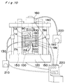
- the molding machine shown in Fig. 10 comprises a stationary lower mold 2A stationarily mounted on a base 120 through a connecting rod 110 and having a lower mold recess defined therein, and a movable upper mold 1A carried by a piston rod 170 through a connecting rod 180 and having an upper mold recess defined therein.
- An optical glass block 300 seated in the lower mold recess is heated by a heater 190 to a required molding temperature.
- the upper mold 1A is lowered to contact the optical glass block 300.
- the upper mold 1A undergoes a vertical oscillatory motion while applying a pulsating pressure to the optical glass block.
- a servo pulsar or pulsator 160 This is carried out by the use of, for example, a servo pulsar or pulsator 160.
- the application of the pulsating pressure is continued until the optical glass block is deformed 90% relative to the initial shape thereof, and the remaining 1% deformation is carried out a constant application of the pressure while the optical glass block has been heated to the required molding temperature.
- the molding machine is powered off when 100% deformation of the optical glass block 300 has been completed, and the upper and lower molds are, after the temperature has lowered sufficiently, separated to remove the optical element.
- the glass cobs prepared from a molten glass are employed each for the optical raw material, the glass cobs usually have different weights and irregular surfaces and, therefore, the temperature tends to vary from one glass cob to another during the molding. Because of this, the resultant optical element is susceptible to thermal shrinkage to an extent as to make it difficult to exhibit desired optical characteristics.
- the present invention is intended to provide an improved molding machine effective to mass-produce optical elements efficiently and accurately at a substantially reduced cost.
- the present invention is featured in that, during an execution of the method comprising a step of inserting an optical raw material between first and second molds, a step of heating the optical raw material to soften and a step of applying pressure to the softened optical raw material by clamping one of the first and second molds to the other thereof, either the amount of deformation of the optical raw material being molded or the temperature of one of the optical raw material being molded and the mold assembly is measured so that at least one of molding conditions to be employed subsequent to the measurement can be controlled.
- the resultant optical element can exhibit considerably improved optical characteristics.
- the present invention brings about the following advantages. Measurement of either the amount of deformation of the optical raw material being molded or the temperature of one of the optical raw material being molded and the mold assembly provides parameters with which at least one of such molding conditions as molding pressure, pressure applying time, pressure release time and frequency of pressure application, to be employed subsequent to the measurement can be controlled. Accordingly, even where the mold assemblies and the optical raw material have variation, the resultant optical element can exhibit considerably improved optical characteristics.
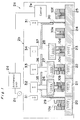
- a molding machine 2b for performing a molding method of the present invention comprises a first preheating stand 20, a second preheating stand 21, a molding stand 22, a first cooling stand 23, a second cooling stand 24, a disassembly/assembly stand 25, and upper heater blocks 26, 27 and 28 associated with the stands 21, 22 and 23, respectively.
- the stands 20 to 23 and the upper heater blocks 26 to 28 have respective heaters incorporated therein, the temperature of which can be controlled.
- a mold assembly 10 includes upper and lower molds 11 and 12, and a barrel mold 14 adjusted to an arbitrary height so as to avoid any possible axial misalignment between the upper and lower molds 11 and 12 and also so as to render an optical element to have a predetermined thickness.
- the mold assembly is provided in a plural number.
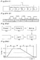
- Reference numerals 10a to 10f represents six mold assemblies which are held in respective conditions assumed at the end of a molding tact. A concept of the molding process according to the illustrated embodiment of the present invention and a temperature profile of the mold assembly are shown in Figs. 3(a) and 3(b), respectively.
- the molding process comprises, mainly, preheating steps, a molding step and cooling steps and, in the practice of the illustrated embodiment, the molding machine provided with two preheating stands, a single molding stand and two cooling stands was employed. Each of these stands is controlled beforehand to attain a predetermined temperature. Change in molding temperature during a period in which the mold assembly 10 is transferred through the various stands 21 to 24 of the molding machine is such as shown in Fig. 3(b).
- the total height, the outer diameter and others of the mold assembly described above are uniformly supervised in the order of microns.
- the heater blocks 25, 26 and 27 above the respective stands are coupled with associated cylinder rods 35 to 37 and capable of being selectively lifted and lowered by corresponding air-cylinders 32 to 34 and apply a desired pressure to the upper molds 11 through the upper heater blocks.
- the cylinder rod 26 is provided with a measuring instrument 2c for measuring the amount of displacement of an optical element.
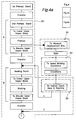
- the measuring instrument is used to measure the amount of displacement of the optical element within the mold assembly at the preheating stand 21 and outputs data which are subsequently supplied to an arithmetic unit. A flow of these data is shown in a molding flowchart shown in Fig. 4.
- a machine control unit 2e After optimum conditions for the molding stand have been selected by the arithmetic unit, conditions are instructed to a machine control unit 2e.
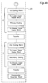
- the molding stand 22 of the molding machine operates according to a command x (Fig. 4) generated from the machine control unit. As shown by y in Fig. 4, it is possible to vary conditions for the first cooling stand.
- Shutters 29 and 30 are simultaneously elevated by the respective air-cylinders 31 at the end of the molding tact time and are lowered after the mold assembly has been transferred onto the next adjacent stand to shield the interior of the molding machine from the outside.
- the interior of the molding machine is supplied with a nitrogen gas to render it to be an reducing atmosphere. This is for the purpose of suppressing oxidization of the mold assembly and the interior of the molding machine.
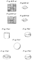
- An optical raw material 1 is a cylindrical block such as shown in Fig. 7(a).
- Fig. 7(b) illustrates a double convexed block
- Fig. 7(c) illustrates a ball block
- Fig. 7(d) illustrates a plano-concave block
- Fig. 7(e) illustrates a glass cob
- the use of the cylindrical block shown in Fig. 7(a) is preferred because of a low cost for the production in the manner described hereinbefore.
- an optical glass SF-8 of 5 mm in diameter and 6 mm in length (having a glass transition temperature of 420°C, a yield temperature of 456°C and a coefficient of linear thermal expansion of 90 ⁇ 10 ⁇ 7/°C at 100 to 300°C) was employed as the optical raw material.
- Temperature settings within the molding machine are as shown in Table 1.
- the upper heater blocks 26 to 28 were adjusted to the same temperatures as the preset temperatures T1 to T3 of the associated stands.
- Table 1 Sites T0 T1 T2 T3 Temperature Settings 70°C 530°C 530°C 400°C
- the optical raw material has its side face finished by the use of a centerless grinding technique to a surface roughness of not greater than 3 ⁇ m.
- This optical raw material also has flat surfaces mirror-polished by the use of a grinding technique to a surface roughness of not greater than 0.1 ⁇ m. Since the optical raw material used in the illustrated embodiment is polished as hereinabove described and has little variation in thickness, little variation is found in weight of the optical raw materials. When this optical raw material undergoes a total displacement of 2mm before the optical raw material is molded under pressure and the molding thereof completes.
- opposite edge portions 43 of the optical raw material are first deformed to conform to respective surface regions of the upper and lower molds 41 and 42, creating closed spaces (only one of which is shown by 44). Once these closed spaces are formed, they exist up until the molding completes, posing a problem in that the shapes of the cavity defining surfaces of the upper and lower molds will not be satisfactorily transcribed onto the optical raw material and a defective optical element will result in.
- the mold assembly 10a is transferred to the first preheating stand 20 within the molding machine and then to the second preheating stand 21 within the molding machine.
- a transfer arm assembly As a means for transferring the mold assembly, the use is made of such a transfer arm assembly as shown by 40 in Fig. 2.
- Figs. 2(a-1) and 2(a-2) illustrate a condition in which the transfer arm assembly is held at a rear position thereby to avoid any possible contact of the transfer arm assembly with the mold assembly.
- the transfer arm assembly advances to a position close to the stands 20 to 24 as shown in Figs. 2(b-1) and 2(b-2). Thereafter, the transfer arm assembly are moved together with the mold assembly towards the disassembly/assembly stand 25 and, after the mold assembly has been transferred, retract to the initial position as shown in Figs. 2(a-2) and 2(a-2).
- the upper heater block 25 is brought into contact with the upper mold 11. While the upper heater block and the lower heater block are required to be heated to a temperature sufficient to cause the glass material to be sufficiently deformed by the application of a pressing force of the mold, it is recommended for them to be heated to a temperature intermediate between the yield temperature of the material and the softening temperature thereof since, if they are heated to an unnecessarily high temperature, the optical element failing to satisfy the desired performance will result in.
- the upper heater block 25 and the preheating stand 21 were heated to 530°C.
- the optical raw material At the time the temperature of the optical raw material attains a temperature of about 530°C, the optical raw material exhibits a viscosity of 109 poises.
- the optical raw material does, when heated to a temperature exceeding the yield temperature of glass, deform little by little under the influence of the weight of the upper heater block.
- the amount of this displacement is measured by the measuring instrument 2c which generate instructions so that molding conditions at the next succeeding molding stand can be modified to optimum molding conditions in dependence on the amount of the displacement.
- Table 1 Total Amt. of Displacement at First Preheating Stand Molding Conditions for Molding Stand Molding Pressure (Kg.cm2) No. of Cycles of Pressure Application Time of One Cycle of Pres. Appln. (sec) 20 to 40 5 3 10 40 to 60 4.5 4 10 60 to 80 4 4 10 80 to 100 3.5 4 8 100 to 120 3 5 8
- the total amount of displacement that took place in the mold assembly No. 1 was 85 ⁇ m. From Table 3, it is clear that the optimum molding pressure is 3.5 Kg/cm2, the number of application of a pressure is 4, and the time during which the pressure is applied is 8 seconds.
- the molding conditions are modified according to the molding flowchart shown in Fig. 4, and the data shown in Table 3 have been inputted beforehand in the arithmetic unit 2d.
- the data on the amount of displacement in each of the mold assembly which have been measured by the measuring instrument 2c installed on the preheating stand 21 are supplied to the arithmetic unit 2d and, within the arithmetic unit, the molding conditions are selected from the data inputted thereto and shown in Table 3 thereby to generate instructions to the machine control unit 2e so that the molding conditions for the molding stand 22 are modified.
- the molding in the mold assembly 10a at the molding stand 22 will be described.
- the molding pressure is zeroed and the upper heater block is elevated to separate from the upper mold.
- the upper heater block is again lowered to tightly contact the upper mold to perform a second cycle of pressure application.
- the molding pressure is again zeroed and the upper heater block is again elevated to separate from the upper mold.
- the upper heater block is elevated to terminate the pressure application.
- the mold assembly 10 is transferred onto the second cooling stand 24.
- the mold assembly is transferred to the disassembly/assembly stand 25 positioned outside the molding machine and is allowed to cool to normal temperatures.
- the upper and lower molds of the mold assembly is separated to remove the completed optical element, followed by a supply of the next succeeding optical raw material.
- the optimum molding conditions for each of the mold assemblies 10b to 10f are calculated by the arithmetic unit 2d from the respective amount of displacement at the associated second preheating stand to modify the molding conditions for the molding stand.
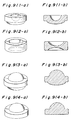
- optical element molded in the manner described above is such as shown in Figs. 9(1-a) and 9(1-b), having met a design shape accurately and having an excellent optical characteristics. It is to be noted that, although the optical raw material used in the illustrated embodiment has been described having its flat surfaces mirror-polished by grinding, an optical raw material of a cylindrical configuration having split surfaces may be employed.
- the molding machine used therein is identical with that used in the first preferred embodiment of the present invention and the mold assemblies are sequentially transferred from one stand to another so that preheating, molding and cooling are successively performed.
- the structure of each of the upper and lower molds is identical with that used in the first preferred embodiment of the present invention and, in consideration of the mass-productivity, a plurality of mold assemblies are provided so that, after introduction of an optical raw material, they are transferred into the molding machine as desired.
- the optical raw material is in the form of a glass cob, as shown in Fig. 7(e), which was prepared by melting an optical glass LF-7 (having a glass transition temperature of 423°C, a yield temperature of 457°C and a coefficient of linear thermal expansion of 107 ⁇ 10 ⁇ 7/°C at 100 to 300°C) and then dropping the melt glass into a receptacle.
- the total amount of deformation which takes place after the molding of the optical raw material under pressure and before completion of the molding is about 2.5 mm.
- Temperature settings within the molding machine are as shown in Table 4. The upper heater blocks were adjusted to the same temperatures as the preset temperatures of the associated stands. Table 4 Sites T0 T1 T2 T3 Temperature Settings 70°C 500°C 500°C 400°C
- the glass cob referred to above is introduced into the mold assembly. Subsequently, the mold assembly is transferred onto the first preheating stand 21 heated to 500°C and positioned within the molding machine 20, and the upper heater block 25 is lowered and is then retained at a lowered position for 60 seconds. At this time, the upper heater block 25 is held in contact with the mold, applying the weight of the upper heater block to the glass cob. The glass cob deforms little by little under the influence of the weight of the upper heater block when it exceeds the yield temperature of the glass material. This amount of displacement is measured by means of the measuring instrument.
- the amount of displacement varies greatly.
- the relationship between the total amount of displacement at the preheating stand and the optimum molding pressure at the molding stand is shown in Table 5. Selection of the optimum molding conditions is carried out by means of the arithmetic unit as is the case in the first embodiment of the present invention.
- the total amount of displacement of the optical raw material in the mold assembly No. 1 at the first preheating stand used in this illustrated embodiment is 50 ⁇ m, and the optimum molding pressure at the molding stand at this time is 5.5 Kg/mm2 as shown in Table 5.
- the mold assembly No. 1 is transferred from the first preheating stand onto the molding stand, and then the molding is effected by the modified molding pressure. After the passage of 60 seconds and before the mold assembly is transferred onto the first cooling stand 23, the molding under pressure is effected to accomplish a total deformation size of 2.4 mm. Thereafter, at the first cooling stand 23, the upper heater block is lowered to contact the upper mold. The temperature of the first cooling stand 23 has been set to 400°C. After the passage of 60 seconds, the upper heater block is elevated thereby to terminating the application of the molding pressure.
- the mold assembly No. 1 is transferred onto the second cooling stand and, after the passage of 60 seconds, the mold assembly is removed out of the molding machine and is allowed to cool to normal temperatures, followed by separation of the upper and lower molds for the removal of the completed optical element.
- the mold assembly No. 2 at the preheating stand 21 is transferred onto the molding stand 22.
- the total amount of displacement of the optical raw material in the mold assembly No. 2 at the preheating stand 21 was 125 ⁇ m, and the optimum molding pressure at the molding stand at this time is 3.5 Kg/mm2 as shown in Table 5, and therefore, instructions were issued to permit the molding pressure to attain 3.5 Kg/mm2.
- the molding at the molding stand 22 is carried out in the same manner as the mold assembly No. 1, and after 60 seconds, the mold assembly No. 2 is transferred onto the cooling stand. Even at the cooling stand 23, the mold assembly is, after having pressurized and cooled in the same manner as the mold assembly No. 1, transferred ont the second cooling stand 24 and, after the passage of 60 seconds, the mold assembly is removed out of the molding machine, followed by cooling thereof down to normal temperatures before the upper and lower molds are separated from each other for the removal of the completed optical element. In the manner described above, the mold assemblies are sequentially transferred for molding.
- the molded optical element was found to satisfying a design shape, exhibiting an excellent optical characteristic.
- the optimum molding conditions were selected from the amount of displacement of the optical raw material at the preheating stand, similar effects can be obtained even when a surface temperature of the optical raw material or the mold assembly at the first preheating stand so that the molding conditions at the molding stand can be modified according to the value of the temperature so measured.
- no pressure release time is specified, a highly precise optical element can be obtained if the pressure release time is specified for each mold assembly.
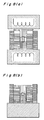
- effects are large if the molding conditions for not only the molding stand, but also for the first cooling stand are modified to the optimum conditions for each mold assembly. Again, the molding can equally be accomplished even if the mold assembly is of a double barrel structure as shown in Fig. 8 wherein Fig.
- Fig. 8(a) illustrates the mold assembly at the second preheating stand
- Fig. 8(b) illustrates the mold assembly at the second cooling stand.
- Representative shapes of the optical elements are shown in Fig. 9 wherein Fig. 9 wherein Figs. 9(1-a) and 9(1-b) show the optical element of a meniscus shape, Figs. 9(2-a) and 9(2-b) show the optical element of a double-concave shape, Figs. 9(3-a) and 9(3-b) show the optical element of a double convex shape, and Figs. 9(4-a) and 9(4-b) show the optical element of a plano-convex shape.
- the molding method of the present invention is effective to manufacture not only the optical element of an axially symmetric shape, but also that having a toric surface or an inclined surface such as observed in a prism.
Landscapes
- Engineering & Computer Science (AREA)
- Chemical & Material Sciences (AREA)
- Manufacturing & Machinery (AREA)
- Materials Engineering (AREA)
- Organic Chemistry (AREA)
- Casting Or Compression Moulding Of Plastics Or The Like (AREA)
- Moulds For Moulding Plastics Or The Like (AREA)
Applications Claiming Priority (2)
| Application Number | Priority Date | Filing Date | Title |
|---|---|---|---|
| JP4274015A JPH06122525A (ja) | 1992-10-13 | 1992-10-13 | 光学素子の成形装置及び成形方法並びに光学素子 |
| JP274015/92 | 1992-10-13 |
Publications (2)
| Publication Number | Publication Date |
|---|---|
| EP0599037A2 true EP0599037A2 (de) | 1994-06-01 |
| EP0599037A3 EP0599037A3 (en) | 1996-01-31 |
Family
ID=17535775
Family Applications (1)
| Application Number | Title | Priority Date | Filing Date |
|---|---|---|---|
| EP93116382A Withdrawn EP0599037A3 (en) | 1992-10-13 | 1993-10-09 | Molding machine for making an optical element and method of making the same. |
Country Status (2)
| Country | Link |
|---|---|
| EP (1) | EP0599037A3 (de) |
| JP (1) | JPH06122525A (de) |
Cited By (5)
| Publication number | Priority date | Publication date | Assignee | Title |
|---|---|---|---|---|
| EP0733598A1 (de) * | 1995-03-22 | 1996-09-25 | Matsushita Electric Industrial Co., Ltd. | Verfahren und Vorrichtung zum Herstellen von optischen Körpern |
| DE19756313A1 (de) * | 1997-12-12 | 1998-06-18 | Heiko Prof Dr Hessenkemper | Meß- und Regeleinrichtung zur Beeinflussung des Kühlprozesses im Formgebungsverfahren von Glasschmelzen und Verfahren zur Durchführung |
| WO1998054102A1 (de) * | 1997-05-31 | 1998-12-03 | Schott Zwiesel Aktiengesellschaft | Verfahren zur herstellung von kelchgläsern, bechern und gleichartigen hohlgläsern und zugehörige vorrichtung zur durchführung des verfahrens |
| US8163209B2 (en) | 2006-11-14 | 2012-04-24 | Airbus Operations Limited | Method and apparatus for controlling the geometry of a composite component |
| TWI483907B (zh) * | 2008-02-28 | 2015-05-11 | 尼康股份有限公司 | The forming method and forming device of optical element |
Families Citing this family (2)
| Publication number | Priority date | Publication date | Assignee | Title |
|---|---|---|---|---|
| JP2008250239A (ja) * | 2007-03-30 | 2008-10-16 | Fujinon Corp | 光学素子成形装置 |
| CN108545917A (zh) * | 2018-06-22 | 2018-09-18 | 惠州达特尔机器人有限公司 | 一种玻璃板热弯成型方法及应用于该方法中的装置 |
-
1992
- 1992-10-13 JP JP4274015A patent/JPH06122525A/ja active Pending
-
1993
- 1993-10-09 EP EP93116382A patent/EP0599037A3/en not_active Withdrawn
Cited By (6)
| Publication number | Priority date | Publication date | Assignee | Title |
|---|---|---|---|---|
| EP0733598A1 (de) * | 1995-03-22 | 1996-09-25 | Matsushita Electric Industrial Co., Ltd. | Verfahren und Vorrichtung zum Herstellen von optischen Körpern |
| US5766294A (en) * | 1995-03-22 | 1998-06-16 | Matsushita Electric Industrial Co, Ltd. | Method and apparatus for producing an optical element using a molding block and a temperature effecting mechanism contacting the molding block for heat exchange |
| WO1998054102A1 (de) * | 1997-05-31 | 1998-12-03 | Schott Zwiesel Aktiengesellschaft | Verfahren zur herstellung von kelchgläsern, bechern und gleichartigen hohlgläsern und zugehörige vorrichtung zur durchführung des verfahrens |
| DE19756313A1 (de) * | 1997-12-12 | 1998-06-18 | Heiko Prof Dr Hessenkemper | Meß- und Regeleinrichtung zur Beeinflussung des Kühlprozesses im Formgebungsverfahren von Glasschmelzen und Verfahren zur Durchführung |
| US8163209B2 (en) | 2006-11-14 | 2012-04-24 | Airbus Operations Limited | Method and apparatus for controlling the geometry of a composite component |
| TWI483907B (zh) * | 2008-02-28 | 2015-05-11 | 尼康股份有限公司 | The forming method and forming device of optical element |
Also Published As
| Publication number | Publication date |
|---|---|
| EP0599037A3 (en) | 1996-01-31 |
| JPH06122525A (ja) | 1994-05-06 |
Similar Documents
| Publication | Publication Date | Title |
|---|---|---|
| KR100774270B1 (ko) | 유리용 프레스 성형 장치 | |
| CN1966435B (zh) | 透镜的制造方法 | |
| JPH0431328A (ja) | 光学素子成形用型構造及びプレス成形方法 | |
| JP3759190B2 (ja) | 光学素子の成形方法 | |
| CN1704367A (zh) | 光学玻璃镜片的模造成形装置及模造成形方法 | |
| KR930006320B1 (ko) | 광학소자 성형용 소재와 광학소자의 제조방법 | |
| CN1178199A (zh) | 光学元件的成型方法 | |
| JPH06122525A (ja) | 光学素子の成形装置及び成形方法並びに光学素子 | |
| JPS62292629A (ja) | ガラスレンズ成形装置 | |
| JP3681114B2 (ja) | ガラス光学素子の製造方法 | |
| JP2746454B2 (ja) | 光学素子の成形方法 | |
| JP2004091281A (ja) | ガラスレンズの製造装置 | |
| JPH0547488B2 (de) | ||
| JPH05124824A (ja) | 光学素子素材及び光学素子の成形方法 | |
| JPS59150728A (ja) | 光学素子の成形方法 | |
| JPH01176237A (ja) | ガラスレンズの成形方法 | |
| JP4436561B2 (ja) | 光学素子の製造方法 | |
| JP3109251B2 (ja) | 光学素子の成形方法 | |
| JPH0741327A (ja) | 光学素子成形方法 | |
| JPH0585747A (ja) | ガラスレンズ成形用型及びガラスレンズ製造方法 | |
| JPH0757697B2 (ja) | ガラスレンズの成形方法 | |
| JPH06279038A (ja) | ガラス成形用金型 | |
| JP4030799B2 (ja) | 光学素子の成形方法 | |
| JP2003183039A (ja) | 光学素子の製造方法 | |
| JPH03279225A (ja) | 光学素子成形装置及び光学素子成形方法 |
Legal Events
| Date | Code | Title | Description |
|---|---|---|---|
| PUAI | Public reference made under article 153(3) epc to a published international application that has entered the european phase |
Free format text: ORIGINAL CODE: 0009012 |
|
| 17P | Request for examination filed |
Effective date: 19931009 |
|
| AK | Designated contracting states |
Kind code of ref document: A2 Designated state(s): DE FR GB |
|
| PUAL | Search report despatched |
Free format text: ORIGINAL CODE: 0009013 |
|
| AK | Designated contracting states |
Kind code of ref document: A3 Designated state(s): DE FR GB |
|
| STAA | Information on the status of an ep patent application or granted ep patent |
Free format text: STATUS: THE APPLICATION HAS BEEN WITHDRAWN |
|
| 18W | Application withdrawn |
Withdrawal date: 19960207 |
|
| R18W | Application withdrawn (corrected) |
Effective date: 19960203 |