EP0599060B1 - Brûleur de dépollution ou de purification d'un moteur à combustion interne - Google Patents
Brûleur de dépollution ou de purification d'un moteur à combustion interne Download PDFInfo
- Publication number
- EP0599060B1 EP0599060B1 EP93117057A EP93117057A EP0599060B1 EP 0599060 B1 EP0599060 B1 EP 0599060B1 EP 93117057 A EP93117057 A EP 93117057A EP 93117057 A EP93117057 A EP 93117057A EP 0599060 B1 EP0599060 B1 EP 0599060B1
- Authority
- EP
- European Patent Office
- Prior art keywords
- fuel
- burner system
- air
- internal combustion
- combustion engine
- Prior art date
- Legal status (The legal status is an assumption and is not a legal conclusion. Google has not performed a legal analysis and makes no representation as to the accuracy of the status listed.)
- Expired - Lifetime
Links
Images


Classifications
-
- F—MECHANICAL ENGINEERING; LIGHTING; HEATING; WEAPONS; BLASTING
- F02—COMBUSTION ENGINES; HOT-GAS OR COMBUSTION-PRODUCT ENGINE PLANTS
- F02M—SUPPLYING COMBUSTION ENGINES IN GENERAL WITH COMBUSTIBLE MIXTURES OR CONSTITUENTS THEREOF
- F02M31/00—Apparatus for thermally treating combustion-air, fuel, or fuel-air mixture
- F02M31/02—Apparatus for thermally treating combustion-air, fuel, or fuel-air mixture for heating
- F02M31/16—Other apparatus for heating fuel
- F02M31/163—Preheating by burning an auxiliary mixture
-
- F—MECHANICAL ENGINEERING; LIGHTING; HEATING; WEAPONS; BLASTING
- F01—MACHINES OR ENGINES IN GENERAL; ENGINE PLANTS IN GENERAL; STEAM ENGINES
- F01N—GAS-FLOW SILENCERS OR EXHAUST APPARATUS FOR MACHINES OR ENGINES IN GENERAL; GAS-FLOW SILENCERS OR EXHAUST APPARATUS FOR INTERNAL-COMBUSTION ENGINES
- F01N3/00—Exhaust or silencing apparatus having means for purifying, rendering innocuous, or otherwise treating exhaust
- F01N3/02—Exhaust or silencing apparatus having means for purifying, rendering innocuous, or otherwise treating exhaust for cooling, or for removing solid constituents of, exhaust
- F01N3/021—Exhaust or silencing apparatus having means for purifying, rendering innocuous, or otherwise treating exhaust for cooling, or for removing solid constituents of, exhaust by means of filters
- F01N3/023—Exhaust or silencing apparatus having means for purifying, rendering innocuous, or otherwise treating exhaust for cooling, or for removing solid constituents of, exhaust by means of filters using means for regenerating the filters, e.g. by burning trapped particles
- F01N3/025—Exhaust or silencing apparatus having means for purifying, rendering innocuous, or otherwise treating exhaust for cooling, or for removing solid constituents of, exhaust by means of filters using means for regenerating the filters, e.g. by burning trapped particles using fuel burner or by adding fuel to exhaust
-
- F—MECHANICAL ENGINEERING; LIGHTING; HEATING; WEAPONS; BLASTING
- F01—MACHINES OR ENGINES IN GENERAL; ENGINE PLANTS IN GENERAL; STEAM ENGINES
- F01N—GAS-FLOW SILENCERS OR EXHAUST APPARATUS FOR MACHINES OR ENGINES IN GENERAL; GAS-FLOW SILENCERS OR EXHAUST APPARATUS FOR INTERNAL-COMBUSTION ENGINES
- F01N3/00—Exhaust or silencing apparatus having means for purifying, rendering innocuous, or otherwise treating exhaust
- F01N3/08—Exhaust or silencing apparatus having means for purifying, rendering innocuous, or otherwise treating exhaust for rendering innocuous
- F01N3/10—Exhaust or silencing apparatus having means for purifying, rendering innocuous, or otherwise treating exhaust for rendering innocuous by thermal or catalytic conversion of noxious components of exhaust
- F01N3/18—Exhaust or silencing apparatus having means for purifying, rendering innocuous, or otherwise treating exhaust for rendering innocuous by thermal or catalytic conversion of noxious components of exhaust characterised by methods of operation; Control
- F01N3/20—Exhaust or silencing apparatus having means for purifying, rendering innocuous, or otherwise treating exhaust for rendering innocuous by thermal or catalytic conversion of noxious components of exhaust characterised by methods of operation; Control specially adapted for catalytic conversion
- F01N3/2006—Periodically heating or cooling catalytic reactors, e.g. at cold starting or overheating
- F01N3/2033—Periodically heating or cooling catalytic reactors, e.g. at cold starting or overheating using a fuel burner or introducing fuel into exhaust duct
-
- F—MECHANICAL ENGINEERING; LIGHTING; HEATING; WEAPONS; BLASTING
- F23—COMBUSTION APPARATUS; COMBUSTION PROCESSES
- F23N—REGULATING OR CONTROLLING COMBUSTION
- F23N1/00—Regulating fuel supply
- F23N1/02—Regulating fuel supply conjointly with air supply
- F23N1/022—Regulating fuel supply conjointly with air supply using electronic means
-
- F—MECHANICAL ENGINEERING; LIGHTING; HEATING; WEAPONS; BLASTING
- F23—COMBUSTION APPARATUS; COMBUSTION PROCESSES
- F23N—REGULATING OR CONTROLLING COMBUSTION
- F23N2223/00—Signal processing; Details thereof
- F23N2223/08—Microprocessor; Microcomputer
-
- F—MECHANICAL ENGINEERING; LIGHTING; HEATING; WEAPONS; BLASTING
- F23—COMBUSTION APPARATUS; COMBUSTION PROCESSES
- F23N—REGULATING OR CONTROLLING COMBUSTION
- F23N2233/00—Ventilators
- F23N2233/06—Ventilators at the air intake
-
- F—MECHANICAL ENGINEERING; LIGHTING; HEATING; WEAPONS; BLASTING
- F23—COMBUSTION APPARATUS; COMBUSTION PROCESSES
- F23N—REGULATING OR CONTROLLING COMBUSTION
- F23N2235/00—Valves, nozzles or pumps
- F23N2235/02—Air or combustion gas valves or dampers
- F23N2235/06—Air or combustion gas valves or dampers at the air intake
-
- F—MECHANICAL ENGINEERING; LIGHTING; HEATING; WEAPONS; BLASTING
- F23—COMBUSTION APPARATUS; COMBUSTION PROCESSES
- F23N—REGULATING OR CONTROLLING COMBUSTION
- F23N2235/00—Valves, nozzles or pumps
- F23N2235/12—Fuel valves
- F23N2235/14—Fuel valves electromagnetically operated
-
- F—MECHANICAL ENGINEERING; LIGHTING; HEATING; WEAPONS; BLASTING
- F23—COMBUSTION APPARATUS; COMBUSTION PROCESSES
- F23N—REGULATING OR CONTROLLING COMBUSTION
- F23N2235/00—Valves, nozzles or pumps
- F23N2235/12—Fuel valves
- F23N2235/16—Fuel valves variable flow or proportional valves
-
- F—MECHANICAL ENGINEERING; LIGHTING; HEATING; WEAPONS; BLASTING
- F23—COMBUSTION APPARATUS; COMBUSTION PROCESSES
- F23N—REGULATING OR CONTROLLING COMBUSTION
- F23N2241/00—Applications
- F23N2241/14—Vehicle heating, the heat being derived otherwise than from the propulsion plant
-
- Y—GENERAL TAGGING OF NEW TECHNOLOGICAL DEVELOPMENTS; GENERAL TAGGING OF CROSS-SECTIONAL TECHNOLOGIES SPANNING OVER SEVERAL SECTIONS OF THE IPC; TECHNICAL SUBJECTS COVERED BY FORMER USPC CROSS-REFERENCE ART COLLECTIONS [XRACs] AND DIGESTS
- Y02—TECHNOLOGIES OR APPLICATIONS FOR MITIGATION OR ADAPTATION AGAINST CLIMATE CHANGE
- Y02A—TECHNOLOGIES FOR ADAPTATION TO CLIMATE CHANGE
- Y02A50/00—TECHNOLOGIES FOR ADAPTATION TO CLIMATE CHANGE in human health protection, e.g. against extreme weather
- Y02A50/20—Air quality improvement or preservation, e.g. vehicle emission control or emission reduction by using catalytic converters
-
- Y—GENERAL TAGGING OF NEW TECHNOLOGICAL DEVELOPMENTS; GENERAL TAGGING OF CROSS-SECTIONAL TECHNOLOGIES SPANNING OVER SEVERAL SECTIONS OF THE IPC; TECHNICAL SUBJECTS COVERED BY FORMER USPC CROSS-REFERENCE ART COLLECTIONS [XRACs] AND DIGESTS
- Y02—TECHNOLOGIES OR APPLICATIONS FOR MITIGATION OR ADAPTATION AGAINST CLIMATE CHANGE
- Y02T—CLIMATE CHANGE MITIGATION TECHNOLOGIES RELATED TO TRANSPORTATION
- Y02T10/00—Road transport of goods or passengers
- Y02T10/10—Internal combustion engine [ICE] based vehicles
- Y02T10/12—Improving ICE efficiencies
Definitions
- the invention relates to a burner system for exhaust gas detoxification or purification of an internal combustion engine according to the preamble of claim 1.
- a secondary air system can be found in the PIERBURG product information 'Electrical secondary air blowers', No. 5 / 400-151.01, 9/91, published at the International Motor Show, Frankfurt / Main, 1991, which is used to blow secondary air into an internal combustion engine Provides exhaust manifold during the cold, not yet operational phase of the catalytic converter.
- the secondary air injection system consists of an air blower, or several check valves and a shut-off valve.
- the emission of HC and CO occurring after the cold start of the internal combustion engine can be considerably reduced or its exit time can be shortened.
- the burner system can also be used for an exhaust gas purification device for diesel engines, consisting of a filter device for collecting carbon particles (soot) and a burner device for burning off the particles deposited on the filter, such as in the unpublished DE patent application P 42 29.103.8 is stated.
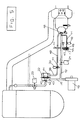
- FIG. 1 shows the overall diagram of a burner system for the application of a catalytic converter starting heater.
- An exhaust pipe 2 leads from an internal combustion engine 1 to a burner 3, which is connected to a catalytic converter 5 via an exhaust gas mixing section 4.
- the burner 3 consists of a mixture preparation chamber 6, a mixture outlet orifice 7, a combustion chamber 8 and a combustion chamber outlet 9.
- An atomizer nozzle 10 opens into the mixture preparation chamber 6 and is supplied with fuel via a fuel line 11 and air via a combustion air line 12 .
- the fuel for the burner system is taken from a fuel distributor line 13, which supplies injection valves 14, which are arranged in intake air channels 15 of the internal combustion engine.
- a safety shut-off valve 16, a fuel regulator 17 and a fuel shut-off valve 18 are arranged in the fuel line 11.
- the combustion air for the burner system is drawn in from the atmosphere by an air blower 19 via an air filter (not shown in the drawing) and is conveyed into a branching secondary air pressure line 20.
- the branching combustion air line 12 leads via a combustion air shut-off valve 21 to the atomizing nozzle 10.
- the secondary air pressure line 20 leads on the one hand to a secondary air pressure regulator 22 and from there to a secondary air shut-off and clock valve 23.
- the secondary air can alternatively be allocated either via a secondary air distributor line 24 and the injection tubes 25 assigned to the cylinder outlet channels take place in the vicinity of the outlet valves in the cylinder head of the internal combustion engine or are assigned to the collecting pipe of the exhaust line 2 via a line 26 shown in broken lines.
- the secondary air conveyed in excess is blown off into the atmosphere by the secondary air pressure regulator 22 via an outlet line 27.
- the rear diaphragm space of the secondary air pressure regulator 22 is in operation of the secondary air blower 19 via a reference pressure line 38, a reference pressure changeover valve 39 and an exhaust pressure line 40 with one of the combustion chambers of the burner 3, here connected to the mixture preparation chamber 6, or the exhaust pipe 2.
- the secondary air pressure regulator 22 is operated via the reference pressure changeover valve 39 connected to atmospheric pressure via an atmospheric pressure line 41.
- An ignition electrode 28, which is controlled via an ignition module 29, serves to ignite the combustion mixture in the combustion chamber 8.
- a flame monitor 30 can be arranged in the area of the mixture preparation chamber 6 or the combustion chamber 8. Furthermore, a lambda probe 31 can be provided for detecting the exhaust gas mixture fed to the catalytic converter 5 directly between the exhaust gas mixing section 4 and the catalytic converter 5, additionally or alternatively to the conventional installation location.
- a temperature sensor 32 serves to detect the catalytic converter temperature on the outer wall or inside the catalytic converter 5. All components of the burner system are connected via connecting lines 33 to an electronic control unit 34, which forms a structural unit with the internal combustion engine management control unit or has an interface with it .
- Air-assisted atomization of the fuel takes place, as can be seen in FIG. 2, in the mixture preparation chamber 6 through the partial flow of the combustion air emerging centrally at the atomizer nozzle 10.
- the radially emerging combustion air represented by arrows surrounds the fuel atomized around the central axis (spray cone) with an air jacket, as a result of which the ignition by means of the ignition electrode 28 and the stability of the flame in the combustion chamber 8 are improved.
- the flame begins in the area of the mixture outlet orifice 7 and extends into the area of the combustion chamber outlet 9.
- the engine exhaust gas flowing in through the exhaust pipe 2 may only mix with the exhaust gas of the combustion chamber 8 in the area of the combustion chamber outlet 9, since otherwise the combustion in the combustion chamber is affected.
- the combustion chamber is therefore designed so that it is in the range of Flame closed and has a reduced cross section in the region of the combustion chamber outlet 9.
- the two exhaust gas flows only meet in the area of the burning flame or through holes 35, whereby mixing of the two exhaust gases in the area of the exhaust gas mixing section 4 is to be promoted through the through holes 35.
- the lambda probe 31 is arranged downstream of the exhaust gas mixing section 4 in order to be able to measure the composition of the total mixture after the mixing has been completed.
- Fig. 3 shows a modified form of the burner 3, in which the combustion chamber outlet 9 has the shape of a cone and the free cross section results from the sum of the through bores 35.
- the selected arrangement of the through bores allows the two exhaust gas flows to be mixed in a more targeted manner, which makes it possible to arrange the lambda probe 31 in the region of the exhaust gas mixing section 4.
- FIG. 4 shows a modified form of the burner 3, in which the mixture outlet orifice 7 between the mixture preparation chamber 6 and the combustion chamber 8 according to FIGS. 1-3 has been replaced by a series of combustion air outlet tubes 36. Instead of the radially escaping combustion air at the atomizing nozzle 10 according to FIGS. 1-3, this is guided over connecting lines 37 and blown in through the combustion air outlet tubes 36 in the separation area of the two chambers.
- the secondary air blower 19 is put into operation when the ignition is switched on and the catalytic converter 5 is not warm and delivers at full power.
- the supply of the burner 3 with combustion air is only required until after 15 to 20 seconds the front part of the catalytic converter 5 is warm from operation or a predetermined temperature threshold value is reached in the catalytic converter.
- the burner 3 is preferably set to lambda just above 1 in the mixing ratio. A constant amount of burner air per unit of time is therefore required for constant burner output and constant lambda.
- the secondary air pressure regulator 22 described below which is shown in its individual parts, is required to avoid a change in the amount of combustion air.
- a valve closing body 42 is connected to a diaphragm 43 and, in the rest position, is pressed onto a valve seat 45 by the force of a compression spring 44.
- the combustion air shutoff valve 21 is opened and the air conveyed by the secondary air blower 19 is conveyed to the atomizing nozzle 10.
- the concentric outlet gap for atomizing the fuel and bores for the radially escaping air are dimensioned so that exactly the amount of air required by the burner is allocated at a certain pressure in the combustion air line 12.
- the spring force is dimensioned such that the closing body 42 opens from this pressure and the excess air flow flows out via the valve seat 45.
- the exhaust gas back pressure rises to values which lead to a reduction in the pressure difference at the atomizing nozzle 10, as a result of which the allocated combustion air is also reduced and the lambda value is changed in the direction of rich.
- the exhaust gas back pressure is conducted via the exhaust gas pressure line 40, the reference pressure changeover valve 39 and the reference pressure line 38 into the membrane chamber of the secondary air pressure regulator 22, in which the compression spring 44 is located.
- the excess air conveyed in the example described here according to FIG. 5 is either supplied to the engine exhaust gas of the individual cylinders via the secondary air shut-off and clock valve 23 via the injection tubes 25 in the area of the exhaust valves or - as shown in dashed lines - via line 26 to the exhaust line 2 (manifold) added.
- the secondary air in the area of the exhaust valves can be used to burn CO and HC.
- the allocation of the secondary air serves to heat the catalyst more evenly during burner operation.
- the lowering of the mixing temperature in the exhaust gas mixing section 4 prevents the end face of the catalyst on the inflow side from overheating and on the other hand ensures that the heating of the catalyst extends deeper through the increased flow rate .
- the lowering of the mixing temperature upstream of the catalytic converter is particularly important if the burner is started a few seconds before the start of the internal combustion engine by means of a preferred circuit and therefore no exhaust gas is yet generated by the internal combustion engine. This procedure is advantageous in terms of reducing exhaust emissions when the engine is started.
- the lambda probe 31 has already reached its operating temperature and the delivery of secondary air beyond the warming-up phase of the catalytic converter 5 is maintained with the secondary air blower 19.
- the metering of the secondary air is taken over by the control of the secondary air shut-off and clock valve 23 by the lambda control.
- the secondary air shut-off and cycle valve 23 can also be designed as a 2/3 way valve (switching from metering and blowing to the atmosphere) in order to improve the allocation of small amounts of secondary air.
- the fuel is supplied when the burner system is used to quickly heat up catalysts, preferably through the fuel line 11 branching off from the fuel rail.
- the metering of a constant amount of fuel is carried out by means of the fuel regulator 17, as shown in detail in FIG. 5.
- the pressure prevailing in the fuel line 11 is passed into both the membrane chamber of the fuel regulator 17 divided by a membrane 47, a fuel nozzle 48 being arranged in the inflow into the membrane chamber from the fuel line 11, and a compression spring 49 being arranged in this membrane chamber, which in the opening direction is one with the Membrane 47 firmly connected closing body 55 acts.
- Fig. 7 shows a burner device with variable burner output, which is required in certain applications, such as for intake air preheating when cold starting diesel engines or for regeneration of diesel soot filters by burning off and with little additional effort on the system components fuel controller 17 and secondary air pressure regulator 22 can be achieved as described below.
- the amount of combustion air can be changed by varying the secondary air pressure, for example by changing the force of the compression spring 44 directly or by means of an additional spring 53 with an electronically controllable servomotor 52.
- the amount of fuel can be changed by varying the pressure difference at the fuel nozzle 48 of the fuel regulator 17, for example by means of an electronically controllable lifting magnet 54.
- the device according to FIG. 7 makes it possible to adapt both the burner output and the mixing ratio of the fuel mixture to the respective requirements in the desired manner.
Landscapes
- Engineering & Computer Science (AREA)
- Chemical & Material Sciences (AREA)
- Combustion & Propulsion (AREA)
- Mechanical Engineering (AREA)
- General Engineering & Computer Science (AREA)
- Chemical Kinetics & Catalysis (AREA)
- Health & Medical Sciences (AREA)
- Toxicology (AREA)
- Exhaust Gas After Treatment (AREA)
- Processes For Solid Components From Exhaust (AREA)
- Incineration Of Waste (AREA)
Claims (10)
- Système de brûleur pour la décontamination et/ou l'épuration des gaz d'échappement d'un moteur à combustion interne, avec lequel un catalyseur, un dispositif de filtration pour capter des particules de carbone, ou l'air comburant du moteur à combustion interne, sont chauffés par le combustible du moteur précité, de l'air comburant, refoulé par un ventilateur d'air, un ventilateur d'air secondaire en particulier, étant fourni à ce système de brûleur, le combustible étant prélevé par l'intermédiaire d'une conduite de combustible, un régulateur de combustible étant disposé dans cette conduite, et un régulateur de pression d'air comburant, alimenté par l'intermédiaire d'une conduite de pression de référence par la pression régnant dans une chambre de combustion du brûleur ou dans le tuyau d'échappement du moteur à combustion interne, étant disposé dans une conduite d'air comburant, prévue entre le ventilateur d'air et le système de brûleur, caractérisé en ce que le régulateur de pression de combustible et/ou d'air comburant (17 et/ou 22) présentent un élément de réglage course/force, attaquable électroniquement et commandé par le biais de signaux pilotes d'un appareil de commande électronique (34), en fonction des paramètres de service du moteur à combustion interne ou du système de brûleur.
- Système de brûleur suivant la revendication 1, caractérisé en ce que le combustible et l'air comburant sont refoulés par l'intermédiaire d'un pulvérisateur (10) dans une chambre de préparation du mélange (6), la chambre de préparation (6) présentant un diaphragme de sortie (7), dans la zone duquel s'engage l'inflammation et se poursuit dans une chambre de combustion (8).
- Système de brûleur suivant la revendication 2, caractérisé en ce que la chambre de combustion (8) présente une sortie (9), qui débouche dans une section de mélange des gaz d'échappement (4), dans laquelle débouchent les gaz d'échappement du moteur à combustion interne.
- Système de brûleur suivant la revendication 3, caractérisé en ce que la sortie de la chambre de combustion (9) présente des orifices de passage (35), dont la disposition est telle qu'un mélange satisfaisant des gaz d'échappement du brûleur et du moteur à combustion interne est obtenu.
- Système de brûleur suivant l'une des revendications précédentes, caractérisé en ce que la conduite de combustible et/ou la conduite d'air comburant présente une soupape de sûreté (16) et une soupape d'arrêt de combustible (18) et/ou une soupape d'arrêt d'air comburant (21).
- Système de brûleur suivant la revendication 5, caractérisé en ce que la sortie de la chambre de combustion (9) présente une surface d'enveloppe conique, dans laquelle les orifices de passage (35) sont prévus et déterminent la section transversale libre, par la somme des orifices de passage/sections transversales.
- Système de brûleur suivant l'une des revendications 2 à 6, caractérisé en ce que le diaphragme de sortie du mélange (7) est formé par une série de tubes de sortie (36) d'air comburant, reliés par une conduite annulaire (37) à la conduite d'air comburant (40).
- Système de brûleur suivant l'une des revendications précédentes, caractérisé en ce que, en liaison avec une injection d'air secondaire, la conduite d'air comburants (20) présente une soupape d'alimentation périodique et d'arrêt d'air secondaire (23).
- Système de brûleur suivant l'une des revendications précédentes, caractérisé en ce que ce système, lors de son utilisation comme dispositif de chauffage de catalyseur ou d'air comburant, est mis en marche par un circuit prioritaire quelques secondes avant le démarrage du moteur à combustion interne.
- Système de brûleur suivant l'une des revendications précédentes, caractérisé en ce qu'il est conçu pour une puissance calorifique constante ou variable.
Applications Claiming Priority (2)
| Application Number | Priority Date | Filing Date | Title |
|---|---|---|---|
| DE4239079 | 1992-11-20 | ||
| DE4239079A DE4239079A1 (de) | 1992-11-20 | 1992-11-20 | Brennersystem zur Abgasentgiftung bzw. -reinigung einer Brennkraftmaschine |
Publications (2)
| Publication Number | Publication Date |
|---|---|
| EP0599060A1 EP0599060A1 (fr) | 1994-06-01 |
| EP0599060B1 true EP0599060B1 (fr) | 1996-01-31 |
Family
ID=6473292
Family Applications (1)
| Application Number | Title | Priority Date | Filing Date |
|---|---|---|---|
| EP93117057A Expired - Lifetime EP0599060B1 (fr) | 1992-11-20 | 1993-10-21 | Brûleur de dépollution ou de purification d'un moteur à combustion interne |
Country Status (5)
| Country | Link |
|---|---|
| US (1) | US5417059A (fr) |
| EP (1) | EP0599060B1 (fr) |
| JP (1) | JPH06207509A (fr) |
| KR (1) | KR940011774A (fr) |
| DE (2) | DE4239079A1 (fr) |
Cited By (2)
| Publication number | Priority date | Publication date | Assignee | Title |
|---|---|---|---|---|
| US8128003B2 (en) | 2005-11-17 | 2012-03-06 | Robert Bosh Gmbh | Burner for heating a catalytic converter with open-loop or closed-loop controlled fuel delivery |
| IT202300020529A1 (it) * | 2023-10-04 | 2025-04-04 | Ferrari Spa | Autoveicolo provvisto di un apparato di post-trattamento ed un dispositivo per riscaldare l'apparato di post-trattamento |
Families Citing this family (83)
| Publication number | Priority date | Publication date | Assignee | Title |
|---|---|---|---|---|
| AU7734294A (en) * | 1993-09-21 | 1995-04-10 | Orbital Engine Company (Australia) Proprietary Limited | Catalytic treatment of engine exhaust gas |
| US5570576A (en) * | 1994-07-05 | 1996-11-05 | General Motors Corporation | Catalyst heater with staged exhaust exotherm |
| DE4430965C2 (de) * | 1994-08-31 | 1997-09-11 | Siemens Ag | Verfahren zum Steuern der Kraftstoffzufuhr für eine Brennkraftmaschine mit beheizbarem Katalysator |
| DE4437655C2 (de) * | 1994-10-21 | 1998-03-26 | Bayerische Motoren Werke Ag | Verfahren zur Überwachung der Funktionsfähigkeit einer Katalysatorheizvorrichtung |
| DE4447286A1 (de) * | 1994-12-30 | 1996-07-04 | Eberspaecher J | Fahrzeugheizgerät mit geregeltem Verbrennungsluftgebläse |
| DE19508013C1 (de) * | 1995-03-07 | 1996-03-14 | Siemens Ag | Vorrichtung und Verfahren zum Aufheizen eines Abgaskatalysators für eine Brennkraftmaschine |
| JPH08284647A (ja) * | 1995-04-10 | 1996-10-29 | Nippon Soken Inc | 内燃機関の排気浄化装置に付設されるhc増量装置 |
| US5829248A (en) * | 1997-06-19 | 1998-11-03 | Environmental Engineering Corp. | Anti-pollution system |
| DE19944388A1 (de) * | 1999-09-16 | 2001-03-22 | Bosch Gmbh Robert | Vorrichtung zum Aufheizen eines Schadstoff-Katalysators |
| US6722123B2 (en) * | 2001-10-17 | 2004-04-20 | Fleetguard, Inc. | Exhaust aftertreatment device, including chemical mixing and acoustic effects |
| US7040088B2 (en) * | 2002-12-20 | 2006-05-09 | Raymond Paul Covit | Diesel engine exhaust purification system |
| US20080028754A1 (en) * | 2003-12-23 | 2008-02-07 | Prasad Tumati | Methods and apparatus for operating an emission abatement assembly |
| US20050147936A1 (en) * | 2004-01-03 | 2005-07-07 | Loving Ronald E. | Heat reactor |
| US7581389B2 (en) * | 2004-01-13 | 2009-09-01 | Emcon Technologies Llc | Method and apparatus for monitoring ash accumulation in a particulate filter of an emission abatement assembly |
| US20050150219A1 (en) * | 2004-01-13 | 2005-07-14 | Crawley Wilbur H. | Method and apparatus for controlling the temperature of a fuel-fired burner of an emission abatement assembly |
| US7628011B2 (en) * | 2004-01-13 | 2009-12-08 | Emcon Technologies Llc | Emission abatement assembly and method of operating the same |
| US7243489B2 (en) * | 2004-01-13 | 2007-07-17 | Arvin Technologies, Inc. | Method and apparatus for monitoring engine performance as a function of soot accumulation in a filter |
| US7908847B2 (en) * | 2004-01-13 | 2011-03-22 | Emcon Technologies Llc | Method and apparatus for starting up a fuel-fired burner of an emission abatement assembly |
| US20050150376A1 (en) * | 2004-01-13 | 2005-07-14 | Crawley Wilbur H. | Method and apparatus for monitoring the components of a control unit of an emission abatement assembly |
| US7025810B2 (en) * | 2004-01-13 | 2006-04-11 | Arvin Technologies, Inc. | Method and apparatus for shutting down a fuel-fired burner of an emission abatement assembly |
| US7118613B2 (en) * | 2004-01-13 | 2006-10-10 | Arvin Technologies, Inc. | Method and apparatus for cooling the components of a control unit of an emission abatement assembly |
| EP1788211A2 (fr) * | 2004-01-13 | 2007-05-23 | Arvin Technologies, Inc. | Procédé et appareil pour ouvrir un brûleur alimenté en carburant sans air d'un assemblage de diminution d'émission |
| US7685811B2 (en) * | 2004-01-13 | 2010-03-30 | Emcon Technologies Llc | Method and apparatus for controlling a fuel-fired burner of an emission abatement assembly |
| US8641411B2 (en) * | 2004-01-13 | 2014-02-04 | Faureua Emissions Control Technologies, USA, LLC | Method and apparatus for directing exhaust gas through a fuel-fired burner of an emission abatement assembly |
| US20050150215A1 (en) * | 2004-01-13 | 2005-07-14 | Taylor William Iii | Method and apparatus for operating an airless fuel-fired burner of an emission abatement assembly |
| US20050150216A1 (en) * | 2004-01-13 | 2005-07-14 | Crawley Wilbur H. | Method and apparatus for cleaning the electrodes of a fuel-fired burner of an emission abatement assembly |
| DE502005007492D1 (de) * | 2004-10-01 | 2009-07-30 | Eberspaecher J Gmbh & Co | Abgasanlage für eine Brennkraftmaschine und zugehöriges Betriebsverfahren |
| US20060218902A1 (en) * | 2005-03-31 | 2006-10-05 | Solar Turbines Incorporated | Burner assembly for particulate trap regeneration |
| DE102005023398A1 (de) * | 2005-05-20 | 2006-11-30 | Arvinmeritor Emissions Technologies Gmbh | Abgasanlage für ein Kraftfahrzeug |
| WO2006137694A1 (fr) * | 2005-06-22 | 2006-12-28 | Korea Institute Of Machinery And Materials | Bruleur destine a la regeneration de filtre contre les matieres en suspension d’un moteur diesel et filtre contre les matières en suspension d'un moteur diesel dote de celui-ci |
| KR100542803B1 (ko) * | 2005-06-22 | 2006-01-11 | 한국기계연구원 | 디젤엔진매연여과장치 재생용 버너 |
| US7406822B2 (en) * | 2005-06-30 | 2008-08-05 | Caterpillar Inc. | Particulate trap regeneration system and control strategy |
| US7481048B2 (en) * | 2005-06-30 | 2009-01-27 | Caterpillar Inc. | Regeneration assembly |
| US20070039315A1 (en) * | 2005-08-17 | 2007-02-22 | Liang Cho Y | Combustion chamber |
| US8196388B2 (en) * | 2005-09-30 | 2012-06-12 | Korea Institute Of Energy Research | Heating device for exhaust gas in internal combustion engine |
| EP1969212A1 (fr) | 2005-12-22 | 2008-09-17 | Grundfos Nonox A/S | Systeme et procede de transfert de fluide |
| US20070158466A1 (en) * | 2005-12-29 | 2007-07-12 | Harmon Michael P | Nozzle assembly |
| FR2897652B1 (fr) * | 2006-02-20 | 2008-04-11 | Renault Sas | Procede et dispositif de coupure d'injection dans une ligne d'echappement |
| US20070228191A1 (en) * | 2006-03-31 | 2007-10-04 | Caterpillar Inc. | Cooled nozzle assembly for urea/water injection |
| US20070235556A1 (en) * | 2006-03-31 | 2007-10-11 | Harmon Michael P | Nozzle assembly |
| US8499739B2 (en) * | 2006-08-31 | 2013-08-06 | Caterpillar Inc. | Injector having tangentially oriented purge line |
| US8215100B2 (en) * | 2007-03-02 | 2012-07-10 | Caterpillar Inc. | Regeneration device having external check valve |
| US8789363B2 (en) * | 2007-06-13 | 2014-07-29 | Faurecia Emissions Control Technologies, Usa, Llc | Emission abatement assembly having a mixing baffle and associated method |
| KR100836261B1 (ko) * | 2008-01-08 | 2008-06-10 | 한국기계연구원 | 디젤엔진 매연여과장치 재생용 버너 및 이를 이용한디젤엔진 매연여과장치 |
| US20090180937A1 (en) * | 2008-01-15 | 2009-07-16 | Nohl John P | Apparatus for Directing Exhaust Flow through a Fuel-Fired Burner of an Emission Abatement Assembly |
| US20090178395A1 (en) * | 2008-01-15 | 2009-07-16 | Huffmeyer Christopher R | Method and Apparatus for Regenerating a Particulate Filter of an Emission Abatement Assembly |
| US20090178391A1 (en) * | 2008-01-15 | 2009-07-16 | Parrish Tony R | Method and apparatus for operating an emission abatement assembly |
| US20090178389A1 (en) * | 2008-01-15 | 2009-07-16 | Crane Jr Samuel N | Method and Apparatus for Controlling a Fuel-Fired Burner of an Emission Abatement Assembly |
| US7980061B2 (en) * | 2008-03-04 | 2011-07-19 | Tenneco Automotive Operating Company Inc. | Charged air bypass for aftertreatment combustion air supply |
| JP5081848B2 (ja) * | 2008-05-15 | 2012-11-28 | 株式会社クボタ | ディーゼルエンジンの排気装置 |
| DE102008032601A1 (de) * | 2008-07-11 | 2010-01-14 | Volkswagen Ag | Verfahren zum Einstellen eines Zustandes eines Abgasstroms einer Brennkraftmaschine eines Kraftfahrzeuges |
| DE102008048529A1 (de) | 2008-09-23 | 2010-03-25 | Beru Ag | Flammglühkerze |
| US20110289906A1 (en) * | 2009-04-27 | 2011-12-01 | Nicholas Morley | Miniature Regeneration Unit |
| US20100307138A1 (en) * | 2009-06-04 | 2010-12-09 | Wen-Lo Chen | Diesel engine exhaust purifier |
| US8397557B2 (en) * | 2009-10-21 | 2013-03-19 | Emcon Technologies Llc | Diagnostic method and apparatus for thermal regenerator after-treatment device |
| EP2554812A1 (fr) * | 2010-04-02 | 2013-02-06 | Toyota Jidosha Kabushiki Kaisha | Dispositif d'évacuation de gaz d'échappement pour moteur à combustion interne |
| US9506385B2 (en) * | 2010-07-15 | 2016-11-29 | Faurecia Emissions Control Technologies, Usa, Llc | Fuel fired burner for vehicle exhaust component |
| JP5383615B2 (ja) * | 2010-09-16 | 2014-01-08 | 日野自動車株式会社 | 後処理バーナシステムの暖機方法 |
| US8464516B2 (en) * | 2010-11-18 | 2013-06-18 | Tenneco Automotive Operating Company Inc. | Inlet for exhaust treatment device |
| US8656708B2 (en) * | 2011-01-31 | 2014-02-25 | Tenneco Automotive Operating Company Inc. | Coaxial inlet and outlet exhaust treatment device |
| US20120294730A1 (en) * | 2011-05-18 | 2012-11-22 | Kline Ronald F | System and method for providing compressed air from an engine |
| US8959902B2 (en) | 2013-02-27 | 2015-02-24 | Tenneco Automotive Operating Company Inc. | Exhaust treatment burner and mixer system |
| US9027332B2 (en) | 2013-02-27 | 2015-05-12 | Tenneco Automotive Operating Company Inc. | Ion sensor with decoking heater |
| US9027331B2 (en) | 2013-02-27 | 2015-05-12 | Tenneco Automotive Operating Company Inc. | Exhaust aftertreatment burner with preheated combustion air |
| US8991163B2 (en) * | 2013-02-27 | 2015-03-31 | Tenneco Automotive Operating Company Inc. | Burner with air-assisted fuel nozzle and vaporizing ignition system |
| KR101321894B1 (ko) * | 2013-04-24 | 2013-10-28 | 이광남 | 정량, 정압 송풍장치를 부착한 매연저감장치용 버너 |
| CN104594991B (zh) * | 2013-10-30 | 2017-05-03 | 乔英电机有限公司 | 智能型滤烟消音装置 |
| US9534525B2 (en) | 2015-05-27 | 2017-01-03 | Tenneco Automotive Operating Company Inc. | Mixer assembly for exhaust aftertreatment system |
| KR102603482B1 (ko) * | 2016-10-26 | 2023-11-16 | 에이치디현대인프라코어 주식회사 | 배기가스 후처리 시스템 |
| KR101849502B1 (ko) * | 2017-12-27 | 2018-04-16 | 정갑철 | 배기가스 이송부가 구비된 매연 저감 장치 |
| WO2020014636A1 (fr) * | 2018-07-12 | 2020-01-16 | Radical Combustion Technologies, Llc | Systèmes, appareil et procédés pour augmenter la température de combustion de mélanges carburant-air dans des moteurs à combustion interne |
| US11118785B2 (en) | 2018-10-26 | 2021-09-14 | Delavan Inc. | Fuel injectors for exhaust heaters |
| WO2021146550A1 (fr) | 2020-01-15 | 2021-07-22 | Radical Combustion Technologies, Llc | Systèmes, appareils et procédés de déclenchement d'allumage par radicaux amélioré dans des moteurs à combustion interne à l'aide d'un générateur de produits chimiques radicalaires |
| DE102020201727A1 (de) * | 2020-02-12 | 2021-08-12 | Hyundai Motor Company | System und Verfahren zur Abgasnachbehandlung |
| DE102020126773B3 (de) * | 2020-10-13 | 2022-02-03 | Dr. Ing. H.C. F. Porsche Aktiengesellschaft | Abgasstrang für ein Kraftfahrzeug, Kraftfahrzeug |
| US11725562B2 (en) | 2020-11-09 | 2023-08-15 | Ford Global Technologies, Llc | Systems and methods for hot air injection into exhaust ports |
| EP4019748B1 (fr) * | 2020-12-23 | 2023-12-06 | Marelli Europe S.p.A. | Dispositif de chauffage d'un système d'échappement d'un moteur à combustion interne |
| IT202100001871A1 (it) * | 2021-01-29 | 2022-07-29 | Marelli Europe Spa | Dispositivo riscaldatore per un sistema di scarico di un motore a combustione interna |
| DE102021001587A1 (de) * | 2021-03-25 | 2022-09-29 | Mercedes-Benz Group AG | Verfahren zum Betreiben eines Brenners eines Kraftfahrzeugs |
| IT202100017255A1 (it) | 2021-06-30 | 2022-12-30 | Marelli Europe Spa | Metodo di controllo di un bruciatore per un sistema di scarico di un motore a combustione interna |
| DE102021119169B4 (de) | 2021-07-23 | 2024-06-13 | Tenneco Gmbh | Abgasteilanlage |
| US11840951B1 (en) * | 2022-12-13 | 2023-12-12 | Fca Us Llc | Exhaust gas burner assembly |
| DE102023209183B3 (de) | 2023-09-20 | 2025-02-27 | Friedrich Boysen Gmbh & Co. Kg | Abgasbrenner und Abgasnachbehandlungssystem |
Family Cites Families (14)
| Publication number | Priority date | Publication date | Assignee | Title |
|---|---|---|---|---|
| GB1008663A (en) * | 1961-11-28 | 1965-11-03 | Lucas Industries Ltd | Combustion apparatus for internal combustion engine exhaust systems |
| US3203168A (en) * | 1962-05-21 | 1965-08-31 | Oxy Catalyst Inc | Method and apparatus for improving the purification of exhaust gases from an internal combustion engine |
| JPS4828820A (fr) * | 1971-08-17 | 1973-04-17 | ||
| JPS5941620A (ja) * | 1982-08-31 | 1984-03-07 | Mazda Motor Corp | ディ−ゼルエンジンの排気ガス浄化装置 |
| JPS5988209U (ja) * | 1982-12-04 | 1984-06-14 | マツダ株式会社 | デイ−ゼルエンジンの排気ガス浄化装置 |
| US4651524A (en) * | 1984-12-24 | 1987-03-24 | Arvin Industries, Inc. | Exhaust processor |
| DE3835939C2 (de) * | 1987-10-31 | 1998-01-15 | Volkswagen Ag | Abgasanlage |
| DE3828248A1 (de) * | 1988-08-19 | 1990-02-22 | Webasto Ag Fahrzeugtechnik | Verfahren zum betreiben eines brenners und brenner hierfuer |
| DE3837472C2 (de) * | 1988-11-04 | 1998-09-24 | Deutz Ag | Partikelfiltersystem |
| JPH02196120A (ja) * | 1989-01-24 | 1990-08-02 | Nissan Motor Co Ltd | 内燃機関の排気微粒子処理装置 |
| US4987738A (en) * | 1989-10-27 | 1991-01-29 | General Motors Corporation | Particulate trap system for an internal combustion engine |
| US5063737A (en) * | 1989-10-27 | 1991-11-12 | General Motors Corporation | Particulate trap system for an internal combustion engine |
| DE4132814C2 (de) * | 1991-10-02 | 1994-02-17 | Pierburg Gmbh | Verfahren und Vorrichtung zur Abgasentgiftung einer Brennkraftmaschine |
| US5320523A (en) * | 1992-08-28 | 1994-06-14 | General Motors Corporation | Burner for heating gas stream |
-
1992
- 1992-11-20 DE DE4239079A patent/DE4239079A1/de not_active Withdrawn
-
1993
- 1993-10-21 DE DE59301554T patent/DE59301554D1/de not_active Expired - Fee Related
- 1993-10-21 EP EP93117057A patent/EP0599060B1/fr not_active Expired - Lifetime
- 1993-11-17 KR KR1019930024435A patent/KR940011774A/ko not_active Withdrawn
- 1993-11-17 JP JP5287932A patent/JPH06207509A/ja active Pending
- 1993-11-22 US US08/156,214 patent/US5417059A/en not_active Expired - Fee Related
Cited By (3)
| Publication number | Priority date | Publication date | Assignee | Title |
|---|---|---|---|---|
| US8128003B2 (en) | 2005-11-17 | 2012-03-06 | Robert Bosh Gmbh | Burner for heating a catalytic converter with open-loop or closed-loop controlled fuel delivery |
| IT202300020529A1 (it) * | 2023-10-04 | 2025-04-04 | Ferrari Spa | Autoveicolo provvisto di un apparato di post-trattamento ed un dispositivo per riscaldare l'apparato di post-trattamento |
| EP4534814A1 (fr) * | 2023-10-04 | 2025-04-09 | FERRARI S.p.A. | Véhicule automobile équipé d'un appareil de post-traitement et d'un dispositif de chauffage de l'appareil de post-traitement |
Also Published As
| Publication number | Publication date |
|---|---|
| US5417059A (en) | 1995-05-23 |
| DE4239079A1 (de) | 1994-05-26 |
| EP0599060A1 (fr) | 1994-06-01 |
| DE59301554D1 (de) | 1996-03-14 |
| KR940011774A (ko) | 1994-06-22 |
| JPH06207509A (ja) | 1994-07-26 |
Similar Documents
| Publication | Publication Date | Title |
|---|---|---|
| EP0599060B1 (fr) | Brûleur de dépollution ou de purification d'un moteur à combustion interne | |
| EP2199678B1 (fr) | Brûleur pour dispositif de chauffage pour véhicule | |
| DE112007002006B4 (de) | Abgasaufbereitungsvorrichtung mit einem kraftstoffbetriebenen Brenner | |
| DE3729861C2 (de) | Verfahren zum Betreiben einer Rußfiltervorrichtung für einen Dieselmotor und Rußfiltervorrichtung zur Durchführung dieses Verfahrens | |
| EP2004962B1 (fr) | Dispositif et procede de production de gaz chaud et systeme de filtration de particules diesel | |
| DE10256769B4 (de) | Kraftfahrzeug mit einem Diesel-Antriebsmotor | |
| EP0238916A1 (fr) | Procédé et dispositif de régénération de systèmes de filtres pour gaz d'échappement | |
| WO2009146771A1 (fr) | Système de post-traitement des gaz d’échappement pour un moteur à combustion interne à auto-allumage | |
| EP0599061B1 (fr) | Méthode de purification de gaz d'échappement d'un moteur à combustion interne | |
| DE102005054733A1 (de) | Brenner zur Katalysatoraufheizung mit gesteuerter oder geregelter Kraftstoffzuführung | |
| EP0417383B1 (fr) | Procédé et dispositif de nettoyage d'un filtre à suie | |
| DE4307525A1 (de) | Verfahren und Vorrichtung zur Nachbehandlung der Abgase einer Brennkraftmaschine | |
| DE2743367C2 (de) | Vergaser für Brennkraftmaschinen | |
| EP1752632B1 (fr) | Dispositif de purification de gaz d'échappement et méthode correspondante | |
| DE3025283A1 (de) | Zusatzheizvorrichtung fuer kraftfahrzeuge | |
| DE4411959A1 (de) | Vorrichtung und Verfahren zur Vorwärmung der Ansaugluft einer Diesel-Brennkraftmaschine | |
| EP0556693A1 (fr) | Brûleur pour combustible liquide | |
| WO2008012005A1 (fr) | Moteur à combustion interne à allumage commandé pour carburants gazeux, et procédé de fonctionnement d'un tel moteur à combustion interne | |
| DE4242091C2 (de) | Vorrichtung zum Starten des Regenerationsbrenners eines Partikelfiltersystems bei niedrigen Temperaturen | |
| DE4416014A1 (de) | Verfahren und Vorrichtung zur Verbesserung der Reinigung des Abgases eines Verbrennungsmotors mit einer Abgasreinigungsanlage, insbesondere in einem Kraftfahrzeug | |
| EP4056896A1 (fr) | Système de brûleur pour préchauffer un système de nettoyage des gaz d'échappement | |
| DE10144406C1 (de) | Heizgerät, insbesondere Zusatzheizgerät für mobile Anwendungen | |
| WO2012016817A1 (fr) | Brûleur à pulvérisation stable en cas de faible contre-pression | |
| DE102024210099B3 (de) | Verfahren zum Betreiben eines Verbrennungsmotors mit einer Abgasanlage sowie Verbrennungsmotor mit einer solchen Abgasanlage | |
| DE3939958A1 (de) | Verfahren zum betreiben eines brenners |
Legal Events
| Date | Code | Title | Description |
|---|---|---|---|
| PUAI | Public reference made under article 153(3) epc to a published international application that has entered the european phase |
Free format text: ORIGINAL CODE: 0009012 |
|
| 17P | Request for examination filed |
Effective date: 19931030 |
|
| AK | Designated contracting states |
Kind code of ref document: A1 Designated state(s): DE FR GB IT |
|
| 17Q | First examination report despatched |
Effective date: 19950224 |
|
| RAP3 | Party data changed (applicant data changed or rights of an application transferred) |
Owner name: PIERBURG GMBH |
|
| GRAA | (expected) grant |
Free format text: ORIGINAL CODE: 0009210 |
|
| AK | Designated contracting states |
Kind code of ref document: B1 Designated state(s): DE FR GB IT |
|
| ITF | It: translation for a ep patent filed | ||
| REF | Corresponds to: |
Ref document number: 59301554 Country of ref document: DE Date of ref document: 19960314 |
|
| GBT | Gb: translation of ep patent filed (gb section 77(6)(a)/1977) |
Effective date: 19960227 |
|
| ET | Fr: translation filed | ||
| RAP2 | Party data changed (patent owner data changed or rights of a patent transferred) |
Owner name: PIERBURG AKTIENGESELLSCHAFT |
|
| PLBE | No opposition filed within time limit |
Free format text: ORIGINAL CODE: 0009261 |
|
| STAA | Information on the status of an ep patent application or granted ep patent |
Free format text: STATUS: NO OPPOSITION FILED WITHIN TIME LIMIT |
|
| 26N | No opposition filed | ||
| REG | Reference to a national code |
Ref country code: FR Ref legal event code: CJ |
|
| PGFP | Annual fee paid to national office [announced via postgrant information from national office to epo] |
Ref country code: GB Payment date: 19980914 Year of fee payment: 6 |
|
| PGFP | Annual fee paid to national office [announced via postgrant information from national office to epo] |
Ref country code: FR Payment date: 19980916 Year of fee payment: 6 |
|
| PGFP | Annual fee paid to national office [announced via postgrant information from national office to epo] |
Ref country code: DE Payment date: 19980922 Year of fee payment: 6 |
|
| PG25 | Lapsed in a contracting state [announced via postgrant information from national office to epo] |
Ref country code: GB Free format text: LAPSE BECAUSE OF NON-PAYMENT OF DUE FEES Effective date: 19991021 |
|
| GBPC | Gb: european patent ceased through non-payment of renewal fee |
Effective date: 19991021 |
|
| PG25 | Lapsed in a contracting state [announced via postgrant information from national office to epo] |
Ref country code: FR Free format text: LAPSE BECAUSE OF NON-PAYMENT OF DUE FEES Effective date: 20000630 |
|
| PG25 | Lapsed in a contracting state [announced via postgrant information from national office to epo] |
Ref country code: DE Free format text: LAPSE BECAUSE OF NON-PAYMENT OF DUE FEES Effective date: 20000801 |
|
| REG | Reference to a national code |
Ref country code: FR Ref legal event code: ST |
|
| PG25 | Lapsed in a contracting state [announced via postgrant information from national office to epo] |
Ref country code: IT Free format text: LAPSE BECAUSE OF NON-PAYMENT OF DUE FEES;WARNING: LAPSES OF ITALIAN PATENTS WITH EFFECTIVE DATE BEFORE 2007 MAY HAVE OCCURRED AT ANY TIME BEFORE 2007. THE CORRECT EFFECTIVE DATE MAY BE DIFFERENT FROM THE ONE RECORDED. Effective date: 20051021 |