EP0599123A2 - Système de transfert pour bain et douche, en particulier pour handicapés physiques - Google Patents
Système de transfert pour bain et douche, en particulier pour handicapés physiques Download PDFInfo
- Publication number
- EP0599123A2 EP0599123A2 EP93118105A EP93118105A EP0599123A2 EP 0599123 A2 EP0599123 A2 EP 0599123A2 EP 93118105 A EP93118105 A EP 93118105A EP 93118105 A EP93118105 A EP 93118105A EP 0599123 A2 EP0599123 A2 EP 0599123A2
- Authority
- EP
- European Patent Office
- Prior art keywords
- blades
- row
- bed
- transfer system
- holding device
- Prior art date
- Legal status (The legal status is an assumption and is not a legal conclusion. Google has not performed a legal analysis and makes no representation as to the accuracy of the status listed.)
- Granted
Links
- 238000012546 transfer Methods 0.000 title claims abstract description 43
- 230000001225 therapeutic effect Effects 0.000 claims abstract description 11
- 230000007246 mechanism Effects 0.000 claims abstract description 9
- 239000004033 plastic Substances 0.000 claims abstract description 4
- 238000003287 bathing Methods 0.000 claims description 10
- 239000004793 Polystyrene Substances 0.000 claims description 2
- 229920002223 polystyrene Polymers 0.000 claims description 2
- 238000001035 drying Methods 0.000 abstract description 9
- 238000005406 washing Methods 0.000 abstract description 8
- 244000052616 bacterial pathogen Species 0.000 abstract description 3
- 230000000474 nursing effect Effects 0.000 description 11
- XLYOFNOQVPJJNP-UHFFFAOYSA-N water Substances O XLYOFNOQVPJJNP-UHFFFAOYSA-N 0.000 description 9
- 230000008707 rearrangement Effects 0.000 description 5
- 230000000694 effects Effects 0.000 description 4
- 230000008901 benefit Effects 0.000 description 3
- 238000000034 method Methods 0.000 description 3
- 206010011409 Cross infection Diseases 0.000 description 2
- 230000006835 compression Effects 0.000 description 2
- 238000007906 compression Methods 0.000 description 2
- 230000001419 dependent effect Effects 0.000 description 2
- 238000011161 development Methods 0.000 description 2
- 230000018109 developmental process Effects 0.000 description 2
- 239000004744 fabric Substances 0.000 description 2
- 230000003993 interaction Effects 0.000 description 2
- 238000012544 monitoring process Methods 0.000 description 2
- 230000008569 process Effects 0.000 description 2
- 206010021639 Incontinence Diseases 0.000 description 1
- 241000251133 Sphyrna tiburo Species 0.000 description 1
- 230000008859 change Effects 0.000 description 1
- 238000010276 construction Methods 0.000 description 1
- 229940079593 drug Drugs 0.000 description 1
- 239000003814 drug Substances 0.000 description 1
- 230000003670 easy-to-clean Effects 0.000 description 1
- 230000002349 favourable effect Effects 0.000 description 1
- 239000000463 material Substances 0.000 description 1
- 238000005259 measurement Methods 0.000 description 1
- 238000002483 medication Methods 0.000 description 1
- 230000000149 penetrating effect Effects 0.000 description 1
- 238000010079 rubber tapping Methods 0.000 description 1
- 231100000075 skin burn Toxicity 0.000 description 1
- 239000007787 solid Substances 0.000 description 1
- 229910001220 stainless steel Inorganic materials 0.000 description 1
- 239000010935 stainless steel Substances 0.000 description 1
- 238000004659 sterilization and disinfection Methods 0.000 description 1
- 239000000725 suspension Substances 0.000 description 1
Images
Classifications
-
- A—HUMAN NECESSITIES
- A61—MEDICAL OR VETERINARY SCIENCE; HYGIENE
- A61G—TRANSPORT, PERSONAL CONVEYANCES, OR ACCOMMODATION SPECIALLY ADAPTED FOR PATIENTS OR DISABLED PERSONS; OPERATING TABLES OR CHAIRS; CHAIRS FOR DENTISTRY; FUNERAL DEVICES
- A61G7/00—Beds specially adapted for nursing; Devices for lifting patients or disabled persons
- A61G7/10—Devices for lifting patients or disabled persons, e.g. special adaptations of hoists thereto
- A61G7/1001—Devices for lifting patients or disabled persons, e.g. special adaptations of hoists thereto specially adapted for specific applications
- A61G7/1003—Devices for lifting patients or disabled persons, e.g. special adaptations of hoists thereto specially adapted for specific applications mounted on or in combination with a bath-tub
-
- A—HUMAN NECESSITIES
- A61—MEDICAL OR VETERINARY SCIENCE; HYGIENE
- A61G—TRANSPORT, PERSONAL CONVEYANCES, OR ACCOMMODATION SPECIALLY ADAPTED FOR PATIENTS OR DISABLED PERSONS; OPERATING TABLES OR CHAIRS; CHAIRS FOR DENTISTRY; FUNERAL DEVICES
- A61G7/00—Beds specially adapted for nursing; Devices for lifting patients or disabled persons
- A61G7/10—Devices for lifting patients or disabled persons, e.g. special adaptations of hoists thereto
- A61G7/1013—Lifting of patients by
- A61G7/1019—Vertical extending columns or mechanisms
-
- A—HUMAN NECESSITIES
- A61—MEDICAL OR VETERINARY SCIENCE; HYGIENE
- A61G—TRANSPORT, PERSONAL CONVEYANCES, OR ACCOMMODATION SPECIALLY ADAPTED FOR PATIENTS OR DISABLED PERSONS; OPERATING TABLES OR CHAIRS; CHAIRS FOR DENTISTRY; FUNERAL DEVICES
- A61G7/00—Beds specially adapted for nursing; Devices for lifting patients or disabled persons
- A61G7/10—Devices for lifting patients or disabled persons, e.g. special adaptations of hoists thereto
- A61G7/1049—Attachment, suspending or supporting means for patients
- A61G7/1055—Suspended platforms, frames or sheets for patient in lying position
-
- A—HUMAN NECESSITIES
- A61—MEDICAL OR VETERINARY SCIENCE; HYGIENE
- A61G—TRANSPORT, PERSONAL CONVEYANCES, OR ACCOMMODATION SPECIALLY ADAPTED FOR PATIENTS OR DISABLED PERSONS; OPERATING TABLES OR CHAIRS; CHAIRS FOR DENTISTRY; FUNERAL DEVICES
- A61G2200/00—Information related to the kind of patient or his position
- A61G2200/30—Specific positions of the patient
- A61G2200/32—Specific positions of the patient lying
-
- A—HUMAN NECESSITIES
- A61—MEDICAL OR VETERINARY SCIENCE; HYGIENE
- A61G—TRANSPORT, PERSONAL CONVEYANCES, OR ACCOMMODATION SPECIALLY ADAPTED FOR PATIENTS OR DISABLED PERSONS; OPERATING TABLES OR CHAIRS; CHAIRS FOR DENTISTRY; FUNERAL DEVICES
- A61G7/00—Beds specially adapted for nursing; Devices for lifting patients or disabled persons
- A61G7/10—Devices for lifting patients or disabled persons, e.g. special adaptations of hoists thereto
- A61G7/1073—Parts, details or accessories
- A61G7/1076—Means for rotating around a vertical axis
Definitions
- the present invention relates to a transfer system for bathing and showering, in particular in the case of physically handicapped persons, in order to ensure the safe and convenient transport from bed to bath tub and vice versa in their hygienic and therapeutic care, consisting of a horizontal support arm which at one end in a lifting and the rotating device is mounted and on the other hand has a connecting element to which at least two vertical support rails for receiving support means for the physically handicapped, such as seated or lying shells, are fastened.
- Such transfer devices are commonly used in facilities to facilitate nursing where they serve the transportation and storage of the physically disabled. In bathing facilities, they enable the safe and comfortable transfer of patients into and out of bathtubs that cannot be used by the physically handicapped without outside help.
- the boom is connected to the piston rod of a hydraulic lifting mechanism via a further compression fitting and can thus be raised and lowered and rotated about the cylinder axis. Due to its detachable and adjustable construction concept, this bracket can be dimensionally adjusted during assembly, so that previous measurements are not necessary. It can also turn on easily during operation apparatus and structural changes, changed treatment methods and changing ergonomic requirements can be adapted.
- Such brackets mounted on bathing devices form with their support devices stationary transfer devices that are limited to the area of a bathroom. The transport between patient room and bathroom must be ensured by a separate transport device.
- the aforementioned seating and lying shells can be part of the transport device and can only be connected to the support rails of the transfer device in the bathroom.
- a first disadvantage arises from the fact that the body surface of a patient in the aforementioned seat or lying shell is not accessible from all sides , and it is therefore difficult to dry it so completely after bathing that it can be lowered directly onto the bed or transported over long distances without the risk of a cold. To do this, it would be necessary to relocate the mostly bedridden patients to the seat or bed on which they are currently sitting, or to transfer them to another bed. Both would be possible - if at all - only with great effort and skill on the part of the nursing staff and would mean an increased risk.
- the invention seeks to remedy this.
- the invention as characterized in the claims, solves the problem of creating a transfer system which, with maximum relief for the nursing staff, ensures safe and comfortable patient transfer from bed to bath tub and vice versa and also takes on functions of hygienic and therapeutic care .
- washing and massaging in the bath tub and drying after removal from the bath water should be carried out gently and automatically by the transfer system.
- this object is achieved by the means as characterized in the version of the independent claim.
- Advantageous further developments are specified in the dependent claims.
- the advantages achieved with the invention are the relief of the nursing staff and the possibilities for better patient care. Since the patient transfer and washing, Cash and drying of the applicant according to the transfer device are performed largely automatically, the nursing Persona l of very strenuous, laborious and often risky actions is relieved, and affect this without compromising the quality of patient care.
- the activities of the nursing staff are limited to the coordination, monitoring and monitoring of the automated processes, for which a single nursing person is completely sufficient.
- the drying cycle approximately 5 minutes
- the patient can re-cover the bed and at the same time monitor the patient.
- the shovel bed which is largely made of plastic, is easy to clean and can be disinfected properly in a conventional manner.
- the transfer device according to the application not only facilitates the hygienic but also the therapeutic patient care and that the corresponding measures are carried out particularly gently will. This results in new and better opportunities for patient care. For example, this gentle treatment has made it possible to provide a perfect supply of burns. Medications can also be added to the warm air or whirl water to enable or enhance a therapeutic effect. Another advantage is that the advances made and improvements made in the development and implementation of care measures with the application-based transfer facility lead to their increased use and thus improve the quality and quantity of hygienic and therapeutic patient care.
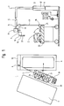
- Fig. 1, 1 denotes the transfer system according to the application, as is used in a station bath for transferring a physically handicapped person 2 between bed 3 and bath tub 4.
- the support arm 5, which is designed as a closed hollow profile with a rectangular cross section, is at one end in the Lifting and rotating device 6 can be raised and lowered and rotatably mounted about the vertical axis 7 and has at its other end a connecting element 9 rotatable about the vertical axis 8.
- the lifting and rotating device 6 is installed in a stationary manner on the foot side 10 of the bathtub 4 and designed as a hydraulic piston / cylinder unit with piston 11 and cylinder 12.
- the bathtub 4 has thermostatically controlled water filling and is set up in a frame made of stainless steel, so that it can be driven under and can be raised to an ergonomically favorable working height (approx. 100 cm).
- the connecting element 9 contains an upper holding device 13 with a schematically indicated warm air supply 14 and a lower holding device 16 which is height-adjustable relative to and relative to the support arm 5 by means of the lifting mechanism 15.
- the vertical support frame 17 carries at its lower end one of support blades 18 and a head part 19 with a joint 20 formed first blade row 21, which is required for all movements of the transfer system 1.
- the support frame 17 is therefore permanently attached to the upper holding device 13.
- the other vertical support frame 23 carries at its lower end in an analogous manner a second row of blades 24 formed from the same support blades 18, which is required for certain functions of the transfer system 1, but must be removed for others. Support frame 23 and row of blades 24 cannot be mounted, for example, in the patient position shown in FIG. 1, which is why they are only indicated in a hint.
- the vertical support frame 23 is therefore easily removable on the lower holding device 16, but still rigid.
- the first row of blades 21 and the second row of blades 24 together form the two-part blade bed 25.
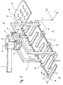
- FIG. 2 shows the connecting element 28 in a more detailed representation, as well as that of the two Support frame 17 and 23 suspended from the support arm 5, formed from the two rows of blades 21 and 24, two-part blade bed 25.
- the connecting element 28 has an outer central vertical axis 29 and can be deflected about the same by a restricted deflection angle ⁇ 360 °. Furthermore, the structure of the connecting element 28 coincides with that of the connecting element 9 in FIG. 1; it again has an upper holding device 13 and a lower holding device 16, to which the first row of blades 21 are fastened via the supporting frame 17 and the second row of blades 24 via the supporting frame 23.
- the lower holding device 16 is equipped with a lifting mechanism 15, so that it can be adjusted in height relative to the support arm 5 and thus also relative to the upper holding device 13.
- the connecting element 28 contains a warm air generator 30 for feeding the air outlet openings 31 in the support blades 18 of the row of blades 21.
- the two-part blade bed 25 is composed of a first row of blades 21 and a second row of blades 24, both of which are mutually height-adjustable, interlock with one another and over which Support frame 17 and 23 are attached to the connecting element 28.
- the first row of blades 21 consists of a holding tube 32 and a warm air tube 33, both of which are held in the connection points 34, 35 on the support frame 17 and on which, for example, 6 support blades 18 are arranged at right angles and parallel to one another.
- the warm air pipe 33 enables warm air to be fed into the carrier blades 18 and, together with the holding tube 32, ensures a solid and sufficiently rigid connection between the carrier blades 18 and the carrier frame 17.
- the carrier blades 18 consist of easily disinfectable plastic. Their mutual distances d and the shape of their upper boundary surfaces 37 are selected so that they form a flat, horizontal lying surface 36 which is also comfortable for the physically handicapped 2.
- the carrying blades 18 are provided with air outlet openings 31, through which warm air is pressed outwards from the inside of the carrying blades 18 can.
- the row of blades 21 has a head part 19, which is connected via a joint 20 to the holding tube 32 and to the warm air pipe 33 and automatically adjusts to the correct back slope when the two-part blade bed 25 is lowered into the bath tub 4. Because of its non-releasable suspension on the upper holding device 13, the first row of blades 21 can be rotated about the vertical axis 29, but is otherwise rigidly connected to the support arm 5 and can only be displaced translationally about this in space.
- the second row of blades 24 is basically constructed in the same way as the first row of blades 21.
- support blades 18 and the associated vertical support frame 23 are connected via a holding tube 40 and a warm air tube 41 to form a torsionally rigid unit which, in contrast to the first row of blades 21, is easily detachable and height-adjustable is fastened to the connecting element 28.
- the lower holding device 16 is designed as an electrical or hydraulic lifting mechanism 15 and the vertical supporting frame 23 is fastened to it in a removable manner or pivoted away laterally or upwards.
- the second row of blades 24 can thus be adjusted in height relative to the first row of blades 21 (and thus also to the horizontal support arm 5).
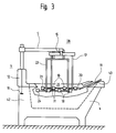
- FIG. 3 illustrates the interaction of transfer device 1 and bathtub 4 to form an integral bathing system for physically handicapped persons 2.
- 11 and 12 denote hydraulic pistons or cylinders, which form the lifting and rotating device 6, and both of which are located in the head-end desk 42 in this exemplary embodiment the bathtub 4 are installed stationary.
- the support arm 5 is pivoted in and lowered over the bathtub 4 in such a way that the two-part scoop bed 25 accommodating the physically disabled 2 is optimally placed in the bathtub 4 in terms of both care and ergonomics.
- the head part 19 is in contact with the tub edge 43 when the two-part bucket bed 25 is lowered, and as a result automatically sets itself into the correct back slope via the joint 20.
- the removable second row of blades 24 fastened to the support frame 23 height adjustable. In the exemplary embodiment shown, it is lowered relative to the first row of blades 21 fastened to the supporting frame 17, so that a physically handicapped person 2 in this case is only supported on the supporting blades 18 of the stationary row of blades 21.
- the height of the support arm 5 is adjusted by means of the lifting and rotating device 6, the vertical movement of the two rows of blades 21; 24 takes place synchronously, thereby lowering or raising the two-part blade bed 25 in the bathtub 4.
- the supporting blades 18 of the first, stationary row of blades 21 have lateral air outlet openings 31 on, can be blown by the warm air against the body of the disabled 2 and against the support blades 18 of the second row of blades 24.
- FIGS. 1, 2 and 3 Attention is drawn to FIGS. 1, 2 and 3, and the starting point is the sequence of movements which is typical for the bathing and showering operation of the physically handicapped. It is assumed that the bed 3 with the physically disabled 2 - for example in the ward bath - has come so close to the bath 4 that bed 3 and bath 4 are located in the area of the transfer system.
- the movement sequence is divided into three phases for better understanding:
- the first phase involves the rearrangement of the physically handicapped 2 from the bed 3 to the two-part shovel head 25 and vice versa:
- the physically handicapped person 2 is brought to the side on the mattress 22 and the first fixed shovel row 21 by actuating the lifting and rotating device 6 from behind brought his back up and lowered onto the mattress 22.
- the support blades 18 press the mattress 22 slightly downward in their areas, so that the physically disabled 2 can be rolled over onto the first row of blades 21 as if by themselves.
- the row of blades 21 is then raised by about 10 cm together with the physically handicapped person 2 supported on it.
- Both the lowering of the row of blades 21 onto the mattress 22 and the subsequent lifting by approximately 10 cm take place by actuating the lifting and rotating device 6.
- the second blade row 24 is brought up to his body from below and the corresponding holding frame 23 in the lower holding device 16 of the connecting element 9 or 28 latched.
- the second row of blades 24 is therefore only attached to the lower holding device 16 after the rearrangement of the physically handicapped 2 has been carried out, and, when the lifting mechanism 15 is lowered, is pivoted in under the first row of blades 21 which has been raised about 10 cm.
- the rearrangement in the opposite direction - ie from the two-part bucket bed 25 to the bed 3 - is carried out in an analogous manner, except that the individual steps are carried out in the reverse order.
- the rearrangement of the physically handicapped 2 is based on the interaction between the two-part bucket bed 25 and a soft base, as well as on the absolute and mutual height adjustment of the two rows of buckets 21 and 24. This rearrangement process is safe and does not require any significant effort on the part of the Nursing staff
- the second phase comprises the transfer of the physically handicapped 2 stored on the two-part scoop bed 25 into and out of the bath tub 4.
- the means of transfer are also means of hygienic and therapeutic care.
- the turbulence generated in the water by the outflowing warm air causes a washing and massage effect on the physically disabled 2.
- the second row of blades 24 is raised and lowered alternately with respect to the first row of blades 21, so that the physically handicapped 2 alternately rests exclusively on the higher row of blades 21 or 24 and his skin is released through the carrying blades 18 of the respectively lower row of blades 21 or 24. This ensures that the washing and massage effect extends over the entire body surface of the physically disabled.
- the warm air is of central importance for the automatic drying of the physically disabled 2 after removal from the bath water.
- the warm air emerging from the air outlet openings 31 flows around the naked patient, who is seated on the two-part scoop bed 25, and dries and warms him. Because of the use of warm air, this is done in a particularly gentle and pleasant way. This can be of great advantage in case of skin burns. Also during automatic drying, the removable, second row of blades 24 is alternately raised and lowered, so that the drying effect also extends essentially over the entire skin surface. Since the drying process, which takes approx. 5 minutes, runs automatically, the caregiver only needs to monitor the patient and can do another job during this time in the ward bath, for example, make a new bed.
- the invention need not be limited to the aforementioned exemplary embodiment.
- the pivoting in and out of the Support arms 5 for transferring patients into and out of the bathtub 4 take place fully automatically, as does switching on the warm air system or alternately raising and lowering the second, removable row of blades 24 when washing, drying or massaging.
- a ceiling-mounted running rail can be provided with a trolley designed as a lifting device, on which the connecting element 9 or 28 can be rotated about a vertical axis.
- the holding tube 32, the warm air tube 33, the support blades 18 and the support frames 17 and 23 can each form an integrating unit which is made of the same material, for example fiber-reinforced polystyrene.
Landscapes
- Health & Medical Sciences (AREA)
- Nursing (AREA)
- Life Sciences & Earth Sciences (AREA)
- Animal Behavior & Ethology (AREA)
- General Health & Medical Sciences (AREA)
- Public Health (AREA)
- Veterinary Medicine (AREA)
- Devices For Medical Bathing And Washing (AREA)
- Invalid Beds And Related Equipment (AREA)
Applications Claiming Priority (2)
| Application Number | Priority Date | Filing Date | Title |
|---|---|---|---|
| CH560/92 | 1992-11-20 | ||
| CH03560/92A CH686658A5 (de) | 1992-11-20 | 1992-11-20 | Transporteinrichtung fuer den Bade- und Duschbetrieb, insbesondere fuer Koerperbehinderte. |
Publications (3)
| Publication Number | Publication Date |
|---|---|
| EP0599123A2 true EP0599123A2 (fr) | 1994-06-01 |
| EP0599123A3 EP0599123A3 (fr) | 1994-08-03 |
| EP0599123B1 EP0599123B1 (fr) | 1997-03-05 |
Family
ID=4258633
Family Applications (1)
| Application Number | Title | Priority Date | Filing Date |
|---|---|---|---|
| EP93118105A Expired - Lifetime EP0599123B1 (fr) | 1992-11-20 | 1993-11-09 | Système de transfert pour bain et douche, en particulier pour handicapés physiques |
Country Status (4)
| Country | Link |
|---|---|
| EP (1) | EP0599123B1 (fr) |
| AT (1) | ATE149336T1 (fr) |
| CH (1) | CH686658A5 (fr) |
| DE (1) | DE59305603D1 (fr) |
Cited By (8)
| Publication number | Priority date | Publication date | Assignee | Title |
|---|---|---|---|---|
| WO1997030674A1 (fr) * | 1996-02-26 | 1997-08-28 | Audun Haugs | Procede et appareil pour bercer une personne sur un lit |
| AT405133B (de) * | 1997-02-04 | 1999-05-25 | Bumba Walter Ing | Einrichtung zur behandlung eines patienten |
| CN109394450A (zh) * | 2018-12-14 | 2019-03-01 | 赣州英博机器人科技有限公司 | 一种多功能护理机器人及其使用方法 |
| CN113018036A (zh) * | 2021-03-24 | 2021-06-25 | 上海佳径智能科技有限公司 | 吊床组件以及带有该吊床组件的护理床 |
| EP3842021A1 (fr) * | 2019-12-23 | 2021-06-30 | Andreas Keibel | Système de transfert et procédé de repositionnement des personnes |
| CN113262119A (zh) * | 2021-05-19 | 2021-08-17 | 洛阳维尔健生物工程有限公司 | 一种平稳可靠的卧床病人转移装置及转移方法 |
| CN113679539A (zh) * | 2021-04-10 | 2021-11-23 | 佛山市鸿鑫智创科技有限公司 | 一种辅助病人转移装置 |
| DE202023001346U1 (de) | 2023-06-27 | 2023-08-29 | Norman Borchardt | Mechatronische Einstiegshilfe |
Families Citing this family (1)
| Publication number | Priority date | Publication date | Assignee | Title |
|---|---|---|---|---|
| CN111202452A (zh) * | 2018-11-22 | 2020-05-29 | 济南汇金电器有限公司 | 一种多功能移动式淋浴屏 |
Family Cites Families (3)
| Publication number | Priority date | Publication date | Assignee | Title |
|---|---|---|---|---|
| US3613127A (en) * | 1969-11-05 | 1971-10-19 | James M Bond | Apparatus facilitating care of a bedfast patient |
| CH659575A5 (de) * | 1983-03-03 | 1987-02-13 | Kurt Brandenberger | Tragvorrichtung fuer eine heb- und drehbare sitz- oder liegeanordnung. |
| DE4012308A1 (de) * | 1990-04-18 | 1991-10-24 | Dietze Werner Dipl Min | Vorrichtung zum heben oder positionieren einer kranken oder behinderten person |
-
1992
- 1992-11-20 CH CH03560/92A patent/CH686658A5/de not_active IP Right Cessation
-
1993
- 1993-11-09 AT AT93118105T patent/ATE149336T1/de not_active IP Right Cessation
- 1993-11-09 EP EP93118105A patent/EP0599123B1/fr not_active Expired - Lifetime
- 1993-11-09 DE DE59305603T patent/DE59305603D1/de not_active Expired - Fee Related
Cited By (11)
| Publication number | Priority date | Publication date | Assignee | Title |
|---|---|---|---|---|
| WO1997030674A1 (fr) * | 1996-02-26 | 1997-08-28 | Audun Haugs | Procede et appareil pour bercer une personne sur un lit |
| AU717745B2 (en) * | 1996-02-26 | 2000-03-30 | Audun Haugs | Method and apparatus for handling of a person in a rocking movement in relation to a bed |
| US6230342B1 (en) | 1996-02-26 | 2001-05-15 | Audun Haugs | Method and apparatus for handling of a person in a rocking movement in relation to a bed |
| AT405133B (de) * | 1997-02-04 | 1999-05-25 | Bumba Walter Ing | Einrichtung zur behandlung eines patienten |
| CN109394450A (zh) * | 2018-12-14 | 2019-03-01 | 赣州英博机器人科技有限公司 | 一种多功能护理机器人及其使用方法 |
| EP3842021A1 (fr) * | 2019-12-23 | 2021-06-30 | Andreas Keibel | Système de transfert et procédé de repositionnement des personnes |
| CN113018036A (zh) * | 2021-03-24 | 2021-06-25 | 上海佳径智能科技有限公司 | 吊床组件以及带有该吊床组件的护理床 |
| CN113018036B (zh) * | 2021-03-24 | 2022-06-24 | 上海佳径智能科技有限公司 | 吊床组件以及带有该吊床组件的护理床 |
| CN113679539A (zh) * | 2021-04-10 | 2021-11-23 | 佛山市鸿鑫智创科技有限公司 | 一种辅助病人转移装置 |
| CN113262119A (zh) * | 2021-05-19 | 2021-08-17 | 洛阳维尔健生物工程有限公司 | 一种平稳可靠的卧床病人转移装置及转移方法 |
| DE202023001346U1 (de) | 2023-06-27 | 2023-08-29 | Norman Borchardt | Mechatronische Einstiegshilfe |
Also Published As
| Publication number | Publication date |
|---|---|
| ATE149336T1 (de) | 1997-03-15 |
| EP0599123B1 (fr) | 1997-03-05 |
| EP0599123A3 (fr) | 1994-08-03 |
| DE59305603D1 (de) | 1997-04-10 |
| CH686658A5 (de) | 1996-05-31 |
Similar Documents
| Publication | Publication Date | Title |
|---|---|---|
| DE3855419T2 (de) | Ein automatisches System zur Pflege bettlägeriger Patienten | |
| DE69421817T2 (de) | Krankenbett | |
| DE2705912A1 (de) | Einrichtung fuer ein bett, insbesondere krankenhausbett | |
| DE3420342A1 (de) | Verfahren und vorrichtung zum aufrichten von gebrechlichen personen | |
| DE2708166C2 (fr) | ||
| DE102016220175A1 (de) | Umlagervorrichtung und Pflegebettanordnung mit einer solchen | |
| EP0599123B1 (fr) | Système de transfert pour bain et douche, en particulier pour handicapés physiques | |
| DE2336452C3 (de) | Transportvorrichtung für eine bettlägerige Person | |
| AT405239B (de) | Krankenbett mit integrierter toilette | |
| EP0117992A1 (fr) | Support pour dispositifs soulevables, tournables, d'assise et de repos | |
| DE4429062A1 (de) | Krankenbett | |
| DE3317598A1 (de) | Umbettungseinrichtung | |
| CH442612A (de) | Mit einer Transport- und Hebeeinrichtung kombinierte Anordnung zum Baden von kranken und alten Personen | |
| EP0100321B1 (fr) | Baignoire d'hopital | |
| DE2634876B2 (de) | Vorrichtung zum Anheben von bettlägerigen Patienten | |
| DE1756102B2 (de) | Vorrichtung mit einem zwecks horizontaler beschickung kippbar an einem traggestell angelenkten wannenfoermigen behaelter | |
| EP0024743B1 (fr) | Lit pour malade et installation de WC s'adaptant dessus | |
| CH669907A5 (en) | Appliance for bathing patients and handicapped persons - has lift unit to raise and lower couch and attached bath | |
| EP4070774A1 (fr) | Dispositif de positionnement permettant de positionner les jambes et utilisation d'un dispositif de positionnement | |
| DE10126668B4 (de) | Toiletteneinrichtung | |
| DE2435497C2 (de) | Für Kranke und Behinderte bestimmtes Bett | |
| DE102006042274A1 (de) | Vorrichtung und Verfahren zum Umlagern einer Person | |
| EP1116455A1 (fr) | Armoire auxiliaire pour lit d'hôpital | |
| CH677181A5 (en) | Splash guard for shower or bath - consists of support frame movable on axle, with curtain | |
| AT405133B (de) | Einrichtung zur behandlung eines patienten |
Legal Events
| Date | Code | Title | Description |
|---|---|---|---|
| PUAI | Public reference made under article 153(3) epc to a published international application that has entered the european phase |
Free format text: ORIGINAL CODE: 0009012 |
|
| AK | Designated contracting states |
Kind code of ref document: A2 Designated state(s): AT BE DE DK FR GB IT NL SE |
|
| PUAL | Search report despatched |
Free format text: ORIGINAL CODE: 0009013 |
|
| AK | Designated contracting states |
Kind code of ref document: A3 Designated state(s): AT BE DE DK FR GB IT NL SE |
|
| 17P | Request for examination filed |
Effective date: 19950125 |
|
| GRAG | Despatch of communication of intention to grant |
Free format text: ORIGINAL CODE: EPIDOS AGRA |
|
| 17Q | First examination report despatched |
Effective date: 19960503 |
|
| GRAH | Despatch of communication of intention to grant a patent |
Free format text: ORIGINAL CODE: EPIDOS IGRA |
|
| GRAH | Despatch of communication of intention to grant a patent |
Free format text: ORIGINAL CODE: EPIDOS IGRA |
|
| GRAA | (expected) grant |
Free format text: ORIGINAL CODE: 0009210 |
|
| AK | Designated contracting states |
Kind code of ref document: B1 Designated state(s): AT BE DE DK FR GB IT NL SE |
|
| PG25 | Lapsed in a contracting state [announced via postgrant information from national office to epo] |
Ref country code: NL Free format text: LAPSE BECAUSE OF FAILURE TO SUBMIT A TRANSLATION OF THE DESCRIPTION OR TO PAY THE FEE WITHIN THE PRESCRIBED TIME-LIMIT Effective date: 19970305 Ref country code: IT Free format text: LAPSE BECAUSE OF FAILURE TO SUBMIT A TRANSLATION OF THE DESCRIPTION OR TO PAY THE FEE WITHIN THE PRE;WARNING: LAPSES OF ITALIAN PATENTS WITH EFFECTIVE DATE BEFORE 2007 MAY HAVE OCCURRED AT ANY TIME BEFORE 2007. THE CORRECT EFFECTIVE DATE MAY BE DIFFERENT FROM THE ONE RECORDED.SCRIBED TIME-LIMIT Effective date: 19970305 Ref country code: GB Effective date: 19970305 Ref country code: FR Effective date: 19970305 Ref country code: DK Effective date: 19970305 |
|
| REF | Corresponds to: |
Ref document number: 149336 Country of ref document: AT Date of ref document: 19970315 Kind code of ref document: T |
|
| REF | Corresponds to: |
Ref document number: 59305603 Country of ref document: DE Date of ref document: 19970410 |
|
| PG25 | Lapsed in a contracting state [announced via postgrant information from national office to epo] |
Ref country code: SE Effective date: 19970605 |
|
| EN | Fr: translation not filed | ||
| NLV1 | Nl: lapsed or annulled due to failure to fulfill the requirements of art. 29p and 29m of the patents act | ||
| GBV | Gb: ep patent (uk) treated as always having been void in accordance with gb section 77(7)/1977 [no translation filed] |
Effective date: 19970305 |
|
| PG25 | Lapsed in a contracting state [announced via postgrant information from national office to epo] |
Ref country code: AT Free format text: LAPSE BECAUSE OF NON-PAYMENT OF DUE FEES Effective date: 19971109 |
|
| PG25 | Lapsed in a contracting state [announced via postgrant information from national office to epo] |
Ref country code: BE Free format text: LAPSE BECAUSE OF NON-PAYMENT OF DUE FEES Effective date: 19971130 |
|
| PLBE | No opposition filed within time limit |
Free format text: ORIGINAL CODE: 0009261 |
|
| STAA | Information on the status of an ep patent application or granted ep patent |
Free format text: STATUS: NO OPPOSITION FILED WITHIN TIME LIMIT |
|
| 26N | No opposition filed | ||
| BERE | Be: lapsed |
Owner name: BRANDENBERGER KURT Effective date: 19971130 |
|
| PG25 | Lapsed in a contracting state [announced via postgrant information from national office to epo] |
Ref country code: DE Free format text: LAPSE BECAUSE OF NON-PAYMENT OF DUE FEES Effective date: 19980801 |