EP0599146B1 - A device for the preparation of mixtures, for example the preparation of dye solutions in textile plants - Google Patents
A device for the preparation of mixtures, for example the preparation of dye solutions in textile plants Download PDFInfo
- Publication number
- EP0599146B1 EP0599146B1 EP93118274A EP93118274A EP0599146B1 EP 0599146 B1 EP0599146 B1 EP 0599146B1 EP 93118274 A EP93118274 A EP 93118274A EP 93118274 A EP93118274 A EP 93118274A EP 0599146 B1 EP0599146 B1 EP 0599146B1
- Authority
- EP
- European Patent Office
- Prior art keywords
- container
- movable structure
- duct
- column
- basin
- Prior art date
- Legal status (The legal status is an assumption and is not a legal conclusion. Google has not performed a legal analysis and makes no representation as to the accuracy of the status listed.)
- Expired - Lifetime
Links
- 239000000203 mixture Substances 0.000 title claims abstract description 6
- 238000002360 preparation method Methods 0.000 title description 14
- 239000004753 textile Substances 0.000 title description 6
- 239000007788 liquid Substances 0.000 claims abstract description 22
- 239000002904 solvent Substances 0.000 claims abstract description 10
- 238000005406 washing Methods 0.000 claims description 15
- 239000012530 fluid Substances 0.000 claims 6
- 238000005086 pumping Methods 0.000 claims 3
- 230000009347 mechanical transmission Effects 0.000 claims 1
- 230000000630 rising effect Effects 0.000 claims 1
- 238000005096 rolling process Methods 0.000 claims 1
- 238000005507 spraying Methods 0.000 claims 1
- 239000000975 dye Substances 0.000 abstract description 24
- 238000011109 contamination Methods 0.000 abstract description 2
- 230000001681 protective effect Effects 0.000 abstract 1
- 239000000243 solution Substances 0.000 description 22
- XLYOFNOQVPJJNP-UHFFFAOYSA-N water Substances O XLYOFNOQVPJJNP-UHFFFAOYSA-N 0.000 description 12
- 239000000843 powder Substances 0.000 description 8
- 230000005540 biological transmission Effects 0.000 description 3
- 230000009471 action Effects 0.000 description 2
- 230000004913 activation Effects 0.000 description 2
- 239000007864 aqueous solution Substances 0.000 description 2
- 238000004043 dyeing Methods 0.000 description 2
- 238000000034 method Methods 0.000 description 2
- 230000008569 process Effects 0.000 description 2
- 230000007420 reactivation Effects 0.000 description 2
- 230000015572 biosynthetic process Effects 0.000 description 1
- 239000006185 dispersion Substances 0.000 description 1
- 238000004090 dissolution Methods 0.000 description 1
- 239000008187 granular material Substances 0.000 description 1
- 239000012456 homogeneous solution Substances 0.000 description 1
- 230000002093 peripheral effect Effects 0.000 description 1
- 239000000523 sample Substances 0.000 description 1
- 239000007787 solid Substances 0.000 description 1
Images

Classifications
-
- B—PERFORMING OPERATIONS; TRANSPORTING
- B01—PHYSICAL OR CHEMICAL PROCESSES OR APPARATUS IN GENERAL
- B01F—MIXING, e.g. DISSOLVING, EMULSIFYING OR DISPERSING
- B01F21/00—Dissolving
- B01F21/10—Dissolving using driven stirrers
-
- B—PERFORMING OPERATIONS; TRANSPORTING
- B01—PHYSICAL OR CHEMICAL PROCESSES OR APPARATUS IN GENERAL
- B01F—MIXING, e.g. DISSOLVING, EMULSIFYING OR DISPERSING
- B01F23/00—Mixing according to the phases to be mixed, e.g. dispersing or emulsifying
- B01F23/50—Mixing liquids with solids
- B01F23/56—Mixing liquids with solids by introducing solids in liquids, e.g. dispersing or dissolving
-
- B—PERFORMING OPERATIONS; TRANSPORTING
- B01—PHYSICAL OR CHEMICAL PROCESSES OR APPARATUS IN GENERAL
- B01F—MIXING, e.g. DISSOLVING, EMULSIFYING OR DISPERSING
- B01F27/00—Mixers with rotary stirring devices in fixed receptacles; Kneaders
- B01F27/80—Mixers with rotary stirring devices in fixed receptacles; Kneaders with stirrers rotating about a substantially vertical axis
- B01F27/805—Mixers with rotary stirring devices in fixed receptacles; Kneaders with stirrers rotating about a substantially vertical axis wherein the stirrers or the receptacles are moved in order to bring them into operative position; Means for fixing the receptacle
- B01F27/806—Mixers with rotary stirring devices in fixed receptacles; Kneaders with stirrers rotating about a substantially vertical axis wherein the stirrers or the receptacles are moved in order to bring them into operative position; Means for fixing the receptacle with vertical displacement of the stirrer, e.g. in combination with means for pivoting the stirrer about a vertical axis in order to co-operate with different receptacles
-
- B—PERFORMING OPERATIONS; TRANSPORTING
- B01—PHYSICAL OR CHEMICAL PROCESSES OR APPARATUS IN GENERAL
- B01F—MIXING, e.g. DISSOLVING, EMULSIFYING OR DISPERSING
- B01F35/00—Accessories for mixers; Auxiliary operations or auxiliary devices; Parts or details of general application
- B01F35/10—Maintenance of mixers
- B01F35/145—Washing or cleaning mixers not provided for in other groups in this subclass; Inhibiting build-up of material on machine parts using other means
- B01F35/1452—Washing or cleaning mixers not provided for in other groups in this subclass; Inhibiting build-up of material on machine parts using other means using fluids
- B01F35/1453—Washing or cleaning mixers not provided for in other groups in this subclass; Inhibiting build-up of material on machine parts using other means using fluids by means of jets of fluid, e.g. air
-
- B—PERFORMING OPERATIONS; TRANSPORTING
- B01—PHYSICAL OR CHEMICAL PROCESSES OR APPARATUS IN GENERAL
- B01F—MIXING, e.g. DISSOLVING, EMULSIFYING OR DISPERSING
- B01F35/00—Accessories for mixers; Auxiliary operations or auxiliary devices; Parts or details of general application
- B01F35/60—Safety arrangements
-
- B—PERFORMING OPERATIONS; TRANSPORTING
- B01—PHYSICAL OR CHEMICAL PROCESSES OR APPARATUS IN GENERAL
- B01F—MIXING, e.g. DISSOLVING, EMULSIFYING OR DISPERSING
- B01F21/00—Dissolving
-
- B—PERFORMING OPERATIONS; TRANSPORTING
- B01—PHYSICAL OR CHEMICAL PROCESSES OR APPARATUS IN GENERAL
- B01F—MIXING, e.g. DISSOLVING, EMULSIFYING OR DISPERSING
- B01F2101/00—Mixing characterised by the nature of the mixed materials or by the application field
- B01F2101/30—Mixing paints or paint ingredients, e.g. pigments, dyes, colours, lacquers or enamel
Definitions
- the present invention relates to a device for the preparation of mixtures according to the pre-characterizing portion of Claim 1, which is known, e.g. from FR-A-1 507 155.
- the invention has been developed with particular concern for its possible use in the preparation of dye solutions in textile plants.
- the powdered dyes are often strongly hygroscopic and thus tend to lump together in the storage containers.
- the powdered dyes are however also volatile; it is thus necessary to prevent the powders from dispersing into the environment and polluting it during the preparation of the solution.
- the object of the present invention is to provide a device which is able to satisfy all the requirements expressed above in an ideal manner.
- this object is achieved by virtue of a device having the further characteristics set forth in claim 1.
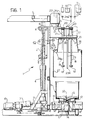
- the device according to the invention (generally indicated 1) is usually intended to be interposed between a station for the taking up and metering of the powdered dyes (not illustrated in the drawings) and a station for their use (also not illustrated explicitly) in which the dye solutions obtained by dissolving the powders in a mass of solvent (usually an aqueous solution) are used for a dyeing process.
- the take-up and metering station supplies, on an output conveyor generally indicated C, basins S or like containers into which a certain quantity of the powdered dyes Q has already been metered in accordance with a given recipe.
- the function of the device 1 according to the invention is essentially that of receiving the basins S on the conveyor C, then providing for the formation of the solutions by the dissolution of the powdered dyes Q in a mass of liquid solvent with intimate and homogeneous mixing of the solution obtained, and subsequent supply of the dye solution thus obtained to a station of use, with washing of the basin S used for the preparation of the dye solution and of parts of the device which have come into contact with the solution itself in order to enable their reuse.
- the process of metering and mixing of the liquids and powders is thus carried out entirely in the basin itself, thereby avoiding a transfer operation irrespective of whether metering is carried out manually or by means of automated apparatus used for this purpose.
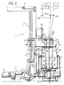
- the device 1 is composed essentially of a bracket structure comprising a column 2 constituted by two rails arranged side-by-side and held substantially vertically by a supporting framework 3 alongside the conveyor C.
- a slide 5 is slidable vertically on the rails under the action of a fluid-pressure actuator 4 and projects from the column 2 so as to overlie the conveyor C on which the basins S are located.
- the actuator 4 is connected by the free end of its shaft to the slide 5 and by the lower end of its body to a pivoted crank structure indicated 6 in turn driven by a further actuator 7.
- the function of the crank 6 is essentially that of moving the body of the actuator 4 slightly away from the column 2 (constituted, as stated, by two adjacent vertical rails between which the actuator 4 itself is interposed) such that the body of latter does not interfere with the downward sliding movement of the structure of the slide 5 when it is lowered towards the basin S as will be explained below.
- a motor 10 which, through a transmission 11, for example a chain and/or gear transmission, drives a support disc 12 on which the basins S are mounted for rotation about a vertical axis.
- a transmission 11 for example a chain and/or gear transmission
- the support disc 12 is mounted on a vertical shaft 13 inserted in a support 14 aligned with the central vertical axis of the basins S and surrounded by an annular tank 15.
- the tank 15 is intended to contain a certain quantity of liquid W with its free surface surrounding the lower end of the peripheral wall of the basin S, at a certain distance therefrom.
- a structure which can to a certain extent be likened to the structure of an electric mixer of the dipper type is mounted on the slide 5.
- a generally horizontal plate or platform 16 is mounted on the slide 5 and a plurality of shafts 18 (for example three, angularly spaced by 120° about the generally circular periphery of the plate 16) are rotatably supported in the plate 16, with the interposition of respective supports 17 fixed to the plate 16 itself, and project a certain distance beneath the plate 16.
- shafts 18 for example three, angularly spaced by 120° about the generally circular periphery of the plate 16
- the lower ends of the shafts 18 support respective helical members or whisks 19, this term being intended to indicate any element which, as a result of the rotation of the respective shaft 18 is able, when immersed in a liquid, to act as a stirrer, agitator or mixer.
- the shafts 18 have keyed to their upper ends which project above the plate 16 respective pulleys 20 about which pass one or more belts (or like transmission elements such as chains) driven, for example, by a drive pulley 21 from a motor 22 whose actuation causes the rotation of the helical members or whisks 19.
- a tubular duct 23 projects downwards from the bracket 2, usually through a distance slightly greater than the length of the shafts 18 and the whisks 19, and is connected to respective pump members 24a, 24b and 24c.
- the pump members in question have the following functions:
- hood or skirt structure generally indicated 25 and including:
- the vertical extent of the cylindrical part 27 is selected so that its said lower edge is located at a certain distance below the helical members or whisks 19 and the lower end of the tubular duct 23 which forms a nozzle 23a.
- the helical members or whisks 19 and the nozzle 23a are intended to cooperate with the bottom portion of the basin S while, as already stated, the lower edge of the cylindrical skirt 27 is intended to be immersed in the annular tank 15.
- the top edge of the cylindrical part 27 surrounds the bottom edge of the frusto-conical part 26 and has a tubular duct 28 provided with a ring of holes 28a opening into the cylindrical part 27.
- a pump member 29 (illustrated schematically in drawings) it is possible to pump water, or another pressurised liquid for washing the hood 25 and the members within it, into the duct 28 and into similar annular washing ducts indicated 30 and 31 which surround the root portions of the duct 23 and the shafts 18.
- the bottom of the basin S is generally conical and upwardly open with a central part, indicated 32, forming a sort of sump in the centre of the bottom.
- the operating sequence of the device according to the invention is driven by a general control member which can be constituted, for example, by an electronic processor or so-called PLC - all according to well known criteria in the art which do not need to be explained here.
- the basin S containing a certain quantity of powdered dyes Q, advances on the conveyor C until it is located beneath the sliding bracket 5, aligned vertically with the members supported thereby, while the bracket 5 itself is held by the actuator 4 in the highest position of its sliding travel along the column 2. Subsequently the actuator 4 is driven so as to lower the slide 5 until it reaches the lowered position illustrated in Figure 2.
- the motor 22 is actuated to rotate the whisks 19 so that these are better able to penetrate the powders Q in the bottom of the basin S.
- the pump member 24a is then activated to pump the liquid intended to act as the solvent for the powdered dyes Q into the basin S through the tubular duct 23 and the nozzle 23a.
- the PLC which controls the device stops the pump member 24a and activates the pump member 24b which makes steam from the generator V flow into the basin S through the duct 23 and the nozzle 23a so as to bring the bath (powders Q plus liquid) in the basin S to the desired dissolving temperature (checked by a probe).
- the pump member 24b is stopped and the motor 22 which drives the fast rotation of the shafts 18 and of the whisks 19 mounted at their ends is started.
- the motor 10 is also activated and rotates the basin S about its central vertical axis. This condition of operation is maintained for a predetermined time interval until an intimate, homogeneous solution of the powdered dyes Q in the liquid introduced into the basin S has been obtained.
- the motors 10 and 22 are stopped and the solution thus prepared is evacuated to the user T by the activation of the pump member 24c (which obviously operates in the opposite sense to that of the pump members 24a and 24b).
- the solution in the basin S is thus drawn through the duct 23 and pumped to the utilisation station (vessel T).
- the nozzle 23a extends into the sump 32 enables the action of evacuating the contents to be entirely effective: during the final phase of the evacuation of the basin S, the final residues of the solution in fact collect in the sump 32 from which they can be collected almost completely as a result of the suction through the nozzle 23a.
- the device is ready for the washing of the basin and of the other parts involved in the preparation of the solution.
- the pump member 29 is activated so as to pump pressurised hot water into the ducts 30 and 31 to wash the shafts 18, the whisks 19, the duct 23 and, indirectly, the inner surface of the basin S as well as, possibly, the outer surface of the basin S (through the duct 28).
- the motors 10 and 22 are again activated.
- the washing phase may be repeated for several cycles, possibly with the replacement of the immission of hot water with the immission of steam taken from the generator V.
- the slide 5 is raised slightly so as to move the helical members or whisks 19 and the nozzle 23a slightly away from the bottom of the basin S.
- the lower edge of the frusto-conical part 26 is raised slightly from the mouth of the basin S.
- the activation of the pump member 30 enables washing water to flow through the duct 28 and to be sprayed particularly towards the mouth of the basin S.
- the water collects in the bottom of the basin S (in which the whisks 19 may be rinsed again by the lowering of the slide 5 and the reactivation of the motor 22) and is evacuated (to the user T or to a drain) by suction through the duct 23.
- a final jet of steam from the generator V usually completes the washing operation.
- the device may return to the starting position illustrated in Figure 1 with the slide 5 moved towards the top of the column 2 so as to allow, as a result of a movement of the conveyor C, the basin S to be removed and a new basin to be used for the preparation of a further dye solution to be supplied to the device 1 itself.
- the whole operation is carried out in a completely automated cycle which avoids the dispersion of powders into the external environment and ensures that all the instruments used for the preparation of each solution are washed completely, avoiding any contamination between solutions prepared subsequently.
- This is all thanks to the vessel 15 and its filling of water (usually with a continuous input and output through a vented tube) which enables the mixing system to be almost hermetically sealed without the use of seals. All this enables the metering (manual or automatic) and mixing of the liquids and powders to be carried out in the same basin S, thus avoiding any transfer operation.
Landscapes
- Chemical & Material Sciences (AREA)
- Chemical Kinetics & Catalysis (AREA)
- Dispersion Chemistry (AREA)
- Treatment Of Fiber Materials (AREA)
- Coloring (AREA)
- Agricultural Chemicals And Associated Chemicals (AREA)
- Detergent Compositions (AREA)
- Accessories For Mixers (AREA)
- Mixers Of The Rotary Stirring Type (AREA)
Applications Claiming Priority (2)
| Application Number | Priority Date | Filing Date | Title |
|---|---|---|---|
| ITTO920960 | 1992-11-27 | ||
| ITTO920960A IT1257556B (it) | 1992-11-27 | 1992-11-27 | Dispositivo per la preparazione di miscele, ad esempio per la preparazione di soluzioni di tintoria in impianti tessili. |
Publications (2)
| Publication Number | Publication Date |
|---|---|
| EP0599146A1 EP0599146A1 (en) | 1994-06-01 |
| EP0599146B1 true EP0599146B1 (en) | 1997-07-02 |
Family
ID=11410885
Family Applications (1)
| Application Number | Title | Priority Date | Filing Date |
|---|---|---|---|
| EP93118274A Expired - Lifetime EP0599146B1 (en) | 1992-11-27 | 1993-11-11 | A device for the preparation of mixtures, for example the preparation of dye solutions in textile plants |
Country Status (8)
| Country | Link |
|---|---|
| US (1) | US5383726A (it) |
| EP (1) | EP0599146B1 (it) |
| JP (1) | JPH06210149A (it) |
| AT (1) | ATE154896T1 (it) |
| DE (1) | DE69311879T2 (it) |
| ES (1) | ES2105048T3 (it) |
| GR (1) | GR3024786T3 (it) |
| IT (1) | IT1257556B (it) |
Families Citing this family (25)
| Publication number | Priority date | Publication date | Assignee | Title |
|---|---|---|---|---|
| DE9410628U1 (de) * | 1994-07-01 | 1994-12-15 | Nijs, Guido, Dipl.-Ing., 73252 Lenningen | Abdeckhaube zur Abdeckung insbesondere von offenen Behältern |
| IT1282436B1 (it) * | 1995-03-21 | 1998-03-23 | Tecnorama Srl | Variante del sistema di erogazione della apparecchiatura di dosaggio di materiali in polvere, granulati e microperle ed abbinamento di |
| IT1276436B1 (it) * | 1995-06-23 | 1997-10-31 | Lawer Srl Ora Lawer S P A | Dispositivo per preparare miscele, ad esempio per sciogliere coloranti in polvere e simili in impianti tessili |
| JP3595892B2 (ja) * | 1995-12-20 | 2004-12-02 | 有限会社勝製作所 | 合成樹脂原料の攪拌装置 |
| NL1022932C2 (nl) * | 2003-03-14 | 2004-09-16 | Stork Prints Bv | Menger met reinigingsinrichting. |
| TW200533566A (en) * | 2004-03-25 | 2005-10-16 | Morohoshi Inc | Method of transporting medicaments |
| US20060156929A1 (en) * | 2005-01-20 | 2006-07-20 | Ned Nelson | Wine punch down unit |
| IT1396371B1 (it) * | 2009-01-14 | 2012-11-19 | Beauty & Business S R L | Dispositivo di pesatura automatica dei coloranti per tinture per capelli e relativo impianto. |
| US9333469B2 (en) * | 2011-03-09 | 2016-05-10 | Distek, Inc. | Multi-motion assembly for leadscrew system |
| DE102012209818A1 (de) * | 2012-06-12 | 2013-12-12 | Erwin Junker Grinding Technology A.S. | Vorrichtung und Verfahren zum Abtrennen von Schleiföl aus Schleifschlämmen |
| WO2015079075A1 (es) * | 2013-11-26 | 2015-06-04 | Ingenieria Y Marketing, S.A. | Equipo portátil de boración de aguas en flujo continuo |
| CN108905730A (zh) * | 2018-06-30 | 2018-11-30 | 白健平 | 一种溶液自动混合装置 |
| CN112516878B (zh) * | 2020-11-23 | 2022-12-16 | 盐城市盛典锅炉制造有限公司 | 一种用于热交换器膨胀水箱的药剂均匀化辅助装置 |
| USD985334S1 (en) | 2020-12-31 | 2023-05-09 | Sharkninja Operating Llc | Nested bowl for a micro puree machine |
| US11154163B1 (en) | 2020-12-31 | 2021-10-26 | Sharkninja Operating Llc | Micro puree machine |
| USD983603S1 (en) | 2020-12-31 | 2023-04-18 | Sharkninja Operating Llc | Blade for a micro puree machine |
| US12016493B2 (en) * | 2020-12-31 | 2024-06-25 | Sharkninja Operating Llc | Micro puree machine |
| US11871765B2 (en) | 2020-12-31 | 2024-01-16 | Sharkninja Operating Llc | Micro puree machine |
| US12016496B2 (en) | 2020-12-31 | 2024-06-25 | Sharkninja Operating Llc | Micro puree machine |
| US12064056B2 (en) | 2020-12-31 | 2024-08-20 | Sharkninja (Hong Kong) Company Limited | Micro puree machine |
| US11925298B2 (en) | 2020-12-31 | 2024-03-12 | Sharkninja Operating Llc | Micro puree machine |
| US11641978B2 (en) | 2020-12-31 | 2023-05-09 | Sharkninja Operating Llc | Micro puree machine |
| USD985331S1 (en) | 2020-12-31 | 2023-05-09 | Sharkninja Operating Llc | Housing for a micro puree machine |
| CN113019179A (zh) * | 2021-02-27 | 2021-06-25 | 周奇艳 | 一种用于纺织的纺织浆液搅拌设备 |
| US12575698B2 (en) | 2021-07-12 | 2026-03-17 | Sharkninja Operating Llc | Micro puree machine with selectable food processing routines and automated motor control |
Family Cites Families (16)
| Publication number | Priority date | Publication date | Assignee | Title |
|---|---|---|---|---|
| FR597966A (fr) * | 1924-05-29 | 1925-12-03 | Baker Perkins Ltd | Perfectionnements dans les appareils mélangeurs |
| US2324179A (en) * | 1942-03-16 | 1943-07-13 | Srob Michael | Mixing machine |
| US2967433A (en) * | 1957-02-15 | 1961-01-10 | Edwin D Phillips | Apparatus for supporting and facilitating the handling of work tools |
| FR1215038A (fr) * | 1958-11-03 | 1960-04-13 | Procédé d'homogénéisation et homogénéiseur à grains calibrés | |
| US3156452A (en) * | 1961-10-10 | 1964-11-10 | Interlake Iron Corp | Mixing apparatus |
| DE1457141A1 (de) * | 1964-10-10 | 1968-12-19 | Gustav Spangenberg Gmbh Maschi | Misch- und Dispergiermaschine |
| CH426735A (de) * | 1965-06-17 | 1966-12-31 | Brogli & Co | Kombinierte Misch- und Homogenisiermaschine |
| US3356350A (en) * | 1966-09-28 | 1967-12-05 | Strathmore Products Inc | Mixing apparatus |
| DE2245302A1 (de) * | 1972-09-15 | 1974-03-28 | Papenmeier Kg Maschf Guenther | Mischer fuer die aufbereitung von staubfoermigem, koernigem, fluessigem, gelartigem oder sonstigem fliessfaehigen mischgut |
| US4095287A (en) * | 1976-03-03 | 1978-06-13 | Bonaval-Werke Gmbh | Emptying apparatus for pasty materials |
| US4647213A (en) * | 1978-03-31 | 1987-03-03 | The Dow Chemical Company | Waste disposal apparatus |
| DE2901176A1 (de) * | 1979-01-13 | 1980-07-24 | Hennecke Gmbh Maschf | Einrichtung zum diskontinuierlichen herstellen von blockschaumstoff |
| US4630932A (en) * | 1986-02-10 | 1986-12-23 | Revelli Anthony J | Dispersing apparatus with wire wheel impeller |
| AU594443B2 (en) * | 1986-03-21 | 1990-03-08 | Kevin John Charles West | Apparatus for mixing and feeding fluid to be applied to particulate material |
| JPH01150508A (ja) * | 1987-12-09 | 1989-06-13 | Taiheiyo Kiko Kk | コンクリートミキサの洗浄方法 |
| US5044762A (en) * | 1990-12-26 | 1991-09-03 | General Signal Corporation | Mixer apparatus for high horse power mixer application where mixer components of large weight and size are supported |
-
1992
- 1992-11-27 IT ITTO920960A patent/IT1257556B/it active IP Right Grant
-
1993
- 1993-11-11 DE DE69311879T patent/DE69311879T2/de not_active Expired - Fee Related
- 1993-11-11 ES ES93118274T patent/ES2105048T3/es not_active Expired - Lifetime
- 1993-11-11 AT AT93118274T patent/ATE154896T1/de active
- 1993-11-11 EP EP93118274A patent/EP0599146B1/en not_active Expired - Lifetime
- 1993-11-17 US US08/154,208 patent/US5383726A/en not_active Expired - Fee Related
- 1993-11-26 JP JP5296429A patent/JPH06210149A/ja active Pending
-
1997
- 1997-09-17 GR GR970402410T patent/GR3024786T3/el unknown
Also Published As
| Publication number | Publication date |
|---|---|
| ATE154896T1 (de) | 1997-07-15 |
| EP0599146A1 (en) | 1994-06-01 |
| ES2105048T3 (es) | 1997-10-16 |
| GR3024786T3 (en) | 1998-01-30 |
| IT1257556B (it) | 1996-01-30 |
| US5383726A (en) | 1995-01-24 |
| DE69311879T2 (de) | 1998-01-02 |
| ITTO920960A0 (it) | 1992-11-27 |
| JPH06210149A (ja) | 1994-08-02 |
| DE69311879D1 (de) | 1997-08-07 |
| ITTO920960A1 (it) | 1994-05-27 |
Similar Documents
| Publication | Publication Date | Title |
|---|---|---|
| US5383726A (en) | Device for the preparation of mixtures, for example the preparation of dye solutions in textile plants | |
| US3690333A (en) | Machine for cleaning small parts | |
| CN1058210C (zh) | 合成树脂颗粒搅拌装置 | |
| CN101657104A (zh) | 自动冷冻甜点搅拌装置以及包括该装置的冷冻甜点生产装置 | |
| EP1288364A2 (en) | Machine and plant for dyeing textile materials | |
| CN210133359U (zh) | 一种日化用品生产用自动化灌装设备 | |
| US4068251A (en) | Developing device for printing plates | |
| JPH05293038A (ja) | 撹拌機 | |
| CN215226795U (zh) | 搅拌装置及饮品制作机 | |
| JP3721042B2 (ja) | ジューサー | |
| EP0734760B1 (en) | Apparatus for the preparation of mixtures, especially dye solutions | |
| EP1431436B1 (en) | Machine for dyeing textile materials | |
| US5437169A (en) | Starch cooking/dispensing apparatus | |
| JP2004073965A (ja) | 真空攪拌装置 | |
| US5735601A (en) | Device for preparing mixtures for dissolving dyes in powder form in textile plants | |
| CN110773022B (zh) | 一种染料自动化料与配送系统 | |
| EP1344859A2 (en) | Basket and process for dyeing textile materials | |
| CA1105449A (en) | Composite wobble plate mixer with recirculating jacket | |
| CN213221968U (zh) | 一种搅拌机构切换装置 | |
| KR101985736B1 (ko) | 떡볶이용 떡 제조를 위한 쌀가루 자동 증숙장치 | |
| CN220589712U (zh) | 一种悬浊液物料恒定固液比的防滴漏定容投料装置 | |
| CN223372758U (zh) | 一种化妆品用灌装装置 | |
| CN208745104U (zh) | 一种带过滤装置的塑胶搅拌机 | |
| JP2001078740A (ja) | 野菜洗浄装置 | |
| CN213311757U (zh) | 一种鲜药熬制设备 |
Legal Events
| Date | Code | Title | Description |
|---|---|---|---|
| PUAI | Public reference made under article 153(3) epc to a published international application that has entered the european phase |
Free format text: ORIGINAL CODE: 0009012 |
|
| AK | Designated contracting states |
Kind code of ref document: A1 Designated state(s): AT BE CH DE DK ES FR GB GR IE IT LI LU MC NL PT SE |
|
| 17P | Request for examination filed |
Effective date: 19940614 |
|
| 17Q | First examination report despatched |
Effective date: 19951026 |
|
| GRAG | Despatch of communication of intention to grant |
Free format text: ORIGINAL CODE: EPIDOS AGRA |
|
| GRAH | Despatch of communication of intention to grant a patent |
Free format text: ORIGINAL CODE: EPIDOS IGRA |
|
| RAP1 | Party data changed (applicant data changed or rights of an application transferred) |
Owner name: LAWER S.P.A. |
|
| GRAH | Despatch of communication of intention to grant a patent |
Free format text: ORIGINAL CODE: EPIDOS IGRA |
|
| GRAA | (expected) grant |
Free format text: ORIGINAL CODE: 0009210 |
|
| AK | Designated contracting states |
Kind code of ref document: B1 Designated state(s): AT BE CH DE DK ES FR GB GR IE IT LI LU MC NL PT SE |
|
| PG25 | Lapsed in a contracting state [announced via postgrant information from national office to epo] |
Ref country code: IT Free format text: LAPSE BECAUSE OF FAILURE TO SUBMIT A TRANSLATION OF THE DESCRIPTION OR TO PAY THE FEE WITHIN THE PRE;WARNING: LAPSES OF ITALIAN PATENTS WITH EFFECTIVE DATE BEFORE 2007 MAY HAVE OCCURRED AT ANY TIME BEFORE 2007. THE CORRECT EFFECTIVE DATE MAY BE DIFFERENT FROM THE ONE RECORDED.SCRIBED TIME-LIMIT Effective date: 19970702 Ref country code: DK Effective date: 19970702 |
|
| REF | Corresponds to: |
Ref document number: 154896 Country of ref document: AT Date of ref document: 19970715 Kind code of ref document: T |
|
| REG | Reference to a national code |
Ref country code: CH Ref legal event code: NV Representative=s name: JACOBACCI & PERANI S.A. Ref country code: CH Ref legal event code: EP |
|
| REF | Corresponds to: |
Ref document number: 69311879 Country of ref document: DE Date of ref document: 19970807 |
|
| ET | Fr: translation filed | ||
| PG25 | Lapsed in a contracting state [announced via postgrant information from national office to epo] |
Ref country code: SE Effective date: 19971002 |
|
| REG | Reference to a national code |
Ref country code: ES Ref legal event code: FG2A Ref document number: 2105048 Country of ref document: ES Kind code of ref document: T3 |
|
| REG | Reference to a national code |
Ref country code: PT Ref legal event code: SC4A Free format text: AVAILABILITY OF NATIONAL TRANSLATION Effective date: 19970703 |
|
| PG25 | Lapsed in a contracting state [announced via postgrant information from national office to epo] |
Ref country code: LU Free format text: LAPSE BECAUSE OF NON-PAYMENT OF DUE FEES Effective date: 19971111 Ref country code: IE Free format text: LAPSE BECAUSE OF NON-PAYMENT OF DUE FEES Effective date: 19971111 |
|
| REG | Reference to a national code |
Ref country code: GR Ref legal event code: FG4A Free format text: 3024786 |
|
| PLBE | No opposition filed within time limit |
Free format text: ORIGINAL CODE: 0009261 |
|
| STAA | Information on the status of an ep patent application or granted ep patent |
Free format text: STATUS: NO OPPOSITION FILED WITHIN TIME LIMIT |
|
| PG25 | Lapsed in a contracting state [announced via postgrant information from national office to epo] |
Ref country code: MC Free format text: LAPSE BECAUSE OF NON-PAYMENT OF DUE FEES Effective date: 19980531 |
|
| 26N | No opposition filed | ||
| PGFP | Annual fee paid to national office [announced via postgrant information from national office to epo] |
Ref country code: AT Payment date: 19991013 Year of fee payment: 7 |
|
| PGFP | Annual fee paid to national office [announced via postgrant information from national office to epo] |
Ref country code: CH Payment date: 19991018 Year of fee payment: 7 |
|
| PGFP | Annual fee paid to national office [announced via postgrant information from national office to epo] |
Ref country code: NL Payment date: 19991027 Year of fee payment: 7 |
|
| PG25 | Lapsed in a contracting state [announced via postgrant information from national office to epo] |
Ref country code: AT Free format text: LAPSE BECAUSE OF NON-PAYMENT OF DUE FEES Effective date: 20001111 |
|
| PG25 | Lapsed in a contracting state [announced via postgrant information from national office to epo] |
Ref country code: LI Free format text: LAPSE BECAUSE OF NON-PAYMENT OF DUE FEES Effective date: 20001130 Ref country code: CH Free format text: LAPSE BECAUSE OF NON-PAYMENT OF DUE FEES Effective date: 20001130 |
|
| PG25 | Lapsed in a contracting state [announced via postgrant information from national office to epo] |
Ref country code: NL Free format text: LAPSE BECAUSE OF NON-PAYMENT OF DUE FEES Effective date: 20010601 |
|
| REG | Reference to a national code |
Ref country code: CH Ref legal event code: PL |
|
| NLV4 | Nl: lapsed or anulled due to non-payment of the annual fee |
Effective date: 20010601 |
|
| REG | Reference to a national code |
Ref country code: GB Ref legal event code: IF02 |
|
| PGFP | Annual fee paid to national office [announced via postgrant information from national office to epo] |
Ref country code: ES Payment date: 20041008 Year of fee payment: 12 Ref country code: GR Payment date: 20041008 Year of fee payment: 12 |
|
| PGFP | Annual fee paid to national office [announced via postgrant information from national office to epo] |
Ref country code: BE Payment date: 20041012 Year of fee payment: 12 |
|
| PGFP | Annual fee paid to national office [announced via postgrant information from national office to epo] |
Ref country code: PT Payment date: 20041021 Year of fee payment: 12 |
|
| PGFP | Annual fee paid to national office [announced via postgrant information from national office to epo] |
Ref country code: GB Payment date: 20041110 Year of fee payment: 12 |
|
| PGFP | Annual fee paid to national office [announced via postgrant information from national office to epo] |
Ref country code: FR Payment date: 20041126 Year of fee payment: 12 |
|
| PGFP | Annual fee paid to national office [announced via postgrant information from national office to epo] |
Ref country code: DE Payment date: 20050128 Year of fee payment: 12 |
|
| PG25 | Lapsed in a contracting state [announced via postgrant information from national office to epo] |
Ref country code: GB Free format text: LAPSE BECAUSE OF NON-PAYMENT OF DUE FEES Effective date: 20051111 |
|
| PG25 | Lapsed in a contracting state [announced via postgrant information from national office to epo] |
Ref country code: ES Free format text: LAPSE BECAUSE OF NON-PAYMENT OF DUE FEES Effective date: 20051112 |
|
| PG25 | Lapsed in a contracting state [announced via postgrant information from national office to epo] |
Ref country code: BE Free format text: LAPSE BECAUSE OF NON-PAYMENT OF DUE FEES Effective date: 20051130 |
|
| PG25 | Lapsed in a contracting state [announced via postgrant information from national office to epo] |
Ref country code: PT Free format text: LAPSE BECAUSE OF NON-PAYMENT OF DUE FEES Effective date: 20060511 |
|
| PG25 | Lapsed in a contracting state [announced via postgrant information from national office to epo] |
Ref country code: DE Free format text: LAPSE BECAUSE OF NON-PAYMENT OF DUE FEES Effective date: 20060601 |
|
| GBPC | Gb: european patent ceased through non-payment of renewal fee |
Effective date: 20051111 |
|
| PG25 | Lapsed in a contracting state [announced via postgrant information from national office to epo] |
Ref country code: FR Free format text: LAPSE BECAUSE OF NON-PAYMENT OF DUE FEES Effective date: 20060731 |
|
| REG | Reference to a national code |
Ref country code: PT Ref legal event code: MM4A Effective date: 20060511 |
|
| REG | Reference to a national code |
Ref country code: FR Ref legal event code: ST Effective date: 20060731 |
|
| REG | Reference to a national code |
Ref country code: ES Ref legal event code: FD2A Effective date: 20051112 |
|
| BERE | Be: lapsed |
Owner name: *LAWER S.P.A. Effective date: 20051130 |
|
| PG25 | Lapsed in a contracting state [announced via postgrant information from national office to epo] |
Ref country code: GR Free format text: LAPSE BECAUSE OF NON-PAYMENT OF DUE FEES Effective date: 19970702 |