EP0599151B1 - Désileuse à couteaux - Google Patents
Désileuse à couteaux Download PDFInfo
- Publication number
- EP0599151B1 EP0599151B1 EP93118317A EP93118317A EP0599151B1 EP 0599151 B1 EP0599151 B1 EP 0599151B1 EP 93118317 A EP93118317 A EP 93118317A EP 93118317 A EP93118317 A EP 93118317A EP 0599151 B1 EP0599151 B1 EP 0599151B1
- Authority
- EP
- European Patent Office
- Prior art keywords
- plate
- side walls
- tines
- silage
- silage cutter
- Prior art date
- Legal status (The legal status is an assumption and is not a legal conclusion. Google has not performed a legal analysis and makes no representation as to the accuracy of the status listed.)
- Expired - Lifetime
Links
Images


Classifications
-
- A—HUMAN NECESSITIES
- A01—AGRICULTURE; FORESTRY; ANIMAL HUSBANDRY; HUNTING; TRAPPING; FISHING
- A01F—PROCESSING OF HARVESTED PRODUCE; HAY OR STRAW PRESSES; DEVICES FOR STORING AGRICULTURAL OR HORTICULTURAL PRODUCE
- A01F25/00—Storing agricultural or horticultural produce; Hanging-up harvested fruit
- A01F25/16—Arrangements in forage silos
- A01F25/20—Unloading arrangements
- A01F25/2027—Unloading arrangements for trench silos
-
- A—HUMAN NECESSITIES
- A01—AGRICULTURE; FORESTRY; ANIMAL HUSBANDRY; HUNTING; TRAPPING; FISHING
- A01F—PROCESSING OF HARVESTED PRODUCE; HAY OR STRAW PRESSES; DEVICES FOR STORING AGRICULTURAL OR HORTICULTURAL PRODUCE
- A01F25/00—Storing agricultural or horticultural produce; Hanging-up harvested fruit
- A01F25/16—Arrangements in forage silos
- A01F25/20—Unloading arrangements
- A01F25/2027—Unloading arrangements for trench silos
- A01F2025/2054—Machinery for cutting successive parallel layers of material in a trench silo
-
- A—HUMAN NECESSITIES
- A01—AGRICULTURE; FORESTRY; ANIMAL HUSBANDRY; HUNTING; TRAPPING; FISHING
- A01F—PROCESSING OF HARVESTED PRODUCE; HAY OR STRAW PRESSES; DEVICES FOR STORING AGRICULTURAL OR HORTICULTURAL PRODUCE
- A01F25/00—Storing agricultural or horticultural produce; Hanging-up harvested fruit
- A01F25/16—Arrangements in forage silos
- A01F25/20—Unloading arrangements
- A01F25/2027—Unloading arrangements for trench silos
- A01F2025/2072—Scoops with an extracting tool mounted inside or in the vicinity of said scoop
Definitions
- the present invention relates to silage cutting pliers according to the preamble of claim 1.
- Such a silage cutter is known for example from EP-A-0 359 482.
- the silage cutting pliers disclosed therein include tines and a block-shear mechanism with stainless steel blades.
- the silage cutter is mounted on an agricultural tractor, driven by it and cuts a silage block from a rental or the like.
- the silage block is conveyed by the device into a container, where it is torn open by a toothed roller and brought into a form that can be easily absorbed by animals.
- silage cutting pliers without such a crushing device, with which the silage cutting pliers are pushed into the rent or the like by the tractor with the upper part open, the tines penetrating into the silage.
- a silage block is then cut out by closing the upper part, the cut edges on the remaining silage being relatively smooth. These smooth edges are desirable in order to limit a material change under the influence of air penetrating through a torn open and thereby enlarged silage surface.
- a disadvantage of the known silage cutting pliers is that the lower part of the pliers consists of a tine grate that is only suitable for relatively long-fiber material, in particular grass silage. Fine grain material, e.g. Silage made from chopped maize or beer spent grains cannot be transported with this, as this material would fall down between the tines. Since many agricultural companies use compound feed, which is mixed together from various of the feed types mentioned, it is therefore necessary to alternately attach the known silage cutting pliers of the known type or a loading shovel to the tractor, depending on which feed type is to be transported.
- the object of the invention is therefore to create a silage cutter with which both long-fiber material and fine-grained material can be cut out and transported.
- a plate which can be pivoted about an axis arranged horizontally in the vicinity of the fastening ends of the tines between an approximately horizontal and an approximately vertical position ensures that long-fibrous material is picked up and conveyed in the usual manner when the plate is in a vertical position can be, the folded-up plate abuts the rear wall and does not hinder the function of the silage cutter, while in the horizontal position of the plate fine-grained material such as a shovel can be picked up without problems, the plate approximately the size of the rust formed by the tines has and rests on it.
- the plate can be pivoted by at least one piston-cylinder unit, one end of which is attached to a strut running between the side walls and the other end of which engages with a lever attached to the rear region of the plate.
- This enables the tractor operator to pivot the plate remotely without having to leave its position.
- the hydraulic medium which is usually present on agricultural tractors in their hydraulic devices is expediently used as the fluid for actuating the piston-cylinder unit. This makes it easy to attach the silage cutter to existing tractors.
- a piston-cylinder unit is provided on each of the two side walls.
- teeth are arranged on the front edge of the plate in order to enable easier penetration into small-part silage or other bulk material.
- the teeth can be angled slightly downward from the plane of the plate in order to facilitate and improve the absorption of cargo from a floor surface.
- the plate has side parts which project upwards at approximately the right angles to the plane of the plate, in order to prevent fine-grained cargo from falling down to the side.
- silage cutting pliers With the silage cutting pliers according to the invention, long-fiber silage as well as fine-grained, loose and pourable feed and other bulk goods such as grain, sand etc. can be transported. This saves one Tractor conversion as previously required.
- the silage cutter is preferably mounted on the front loading arms of a tractor; It can also be attached to the three-point hitch on the rear of a tractor.
- a silage cutter 1 has a rear wall 10 and two side walls 11 connected to it.
- a horizontal axis A is arranged in the upper region of the side walls 11, about which an upper part 14 can be pivoted.
- the upper part 14 comprises two side parts 16 and a front part 17, the lower edges of the side parts 16 and the front part 17 having cutting knives 18.
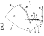
- the silage cutter 1 has a plate 19 which can be pivoted about a horizontal axis B and which is shown in FIG three positions is shown in Figures 1 to 3.
- the plate 19 is shown in an approximately horizontal position and lies on the tines 13. In this position of the plate 19, fine-grained material can be picked up and transported.
- the plate 19 can be pivoted continuously from its horizontal position according to FIG. 1 via an intermediate position shown in FIG. 2 to an approximately vertical position according to FIG. 3, the plate 19 in the approximately vertical position on the rear wall 10 is present.
- the piston-cylinder unit 20 the hydraulic drive of which is not shown, is pivotally attached at one end to a further strut 21, the strut 21 extending approximately horizontally between the side walls 11.
- the other end of the piston-cylinder unit 20 engages a lever 22 which is fastened to the rear region of the plate 19 in such a way that it is pivoted about an axis B when the piston-cylinder unit 20 is adjusted.
- FIG. 4 shows the silage cutting pliers 10 in a top view, here without an upper part 14, the plate 19 with teeth 23 on the front edge being visible from above.
- the teeth 23 are arranged so that the tips of the prongs 13 lie in the tooth gaps. In addition, the teeth 23 are angled slightly downwards relative to the plane of the plate, so that the tips of the teeth can be guided under a good surface along a floor surface under the good.
- the silage cutting pliers 1 can be connected to the front loading arms or the rear three-point coupling of a tractor and can be actuated from there.
Landscapes
- Life Sciences & Earth Sciences (AREA)
- Environmental Sciences (AREA)
- Threshing Machine Elements (AREA)
Claims (5)
- Pince coupante pour ensilage, de préférence destinée à être montée sur un véhicule, et présentant une paroi arrière (10) et deux parois latérales (11) reliées à cette paroi arrière, une pluralité de pointes (13) s'étendant de façon sensiblement horizontale et constituant une grille à dents étant fixée dans la zone intérieure de la paroi arrière (10), tandis qu'une partie supérieure (14) est montée pivotante autour d'un axe horizontal (A) sur les parois latérales (11), cette partie supérieure (14) comprenant deux parois latérales (16) et une partie avant (17) reliée aux parties latérales (16), pince coupante dans laquelle les arêtes inférieures des parties latérales (16) et de la partie avant (17) comprennent des couteaux (18) tandis que la partie supérieure (14) est susceptible d'être entraînée à pivotement par un organe d'actionnement entre une position ouverte et une position fermée, les couteaux (18) étant disposés en position fermée à proximité des pointes (13), caractérisée en ce qu'il est prévu une plaque (19) qui est susceptible de pivoter autour d'un axe (B) disposé horizontalement à proximité des extrémités de fixation des pointes (13), entre une position sensiblement horizontale dans laquelle elle est disposée sur les dents (13) et une position sensiblement verticale, dans laquelle elle est disposée contre la paroi arrière (10), la plaque (19) présentant les dimensions de la grille à dents.
- Pince coupante pour ensilage selon la revendication 1, caractérisée en ce que la plaque (19) est susceptible d'être entraînée en pivotement par au moins une unité piston-cylindre (20), dont l'une des extrémités est fixée à une entretoise (21) s'étendant entre les parois latérales (11) et dont l'autre extrémité est en contact avec un levier (22) fixé dans la zone arrière de la plaque (19).
- Pince coupante pour ensilage selon l'une des revendications précédentes, caractérisée en ce que, sur l'arête avant de la plaque (19), sont montées des dents (23).
- Pince coupante pour ensilage selon la revendication 3, caractérisée en ce que les dents (23) sont repliées vers le bas par rapport au plan de la plaque , sous un angle compris entre 15° et 45°.
- Pince coupante pour ensilage selon l'une des revendications précédentes, caractérisée en ce que la plaque (19) comporte sur les arêtes latérales des parties latérales faisant saillie vers le haut, sensiblement à angle droit par rapport au plan de la plaque.
Applications Claiming Priority (2)
| Application Number | Priority Date | Filing Date | Title |
|---|---|---|---|
| DE9215818U DE9215818U1 (de) | 1992-11-23 | 1992-11-23 | Silageschneidzange |
| DE9215818U | 1992-11-23 |
Publications (2)
| Publication Number | Publication Date |
|---|---|
| EP0599151A1 EP0599151A1 (fr) | 1994-06-01 |
| EP0599151B1 true EP0599151B1 (fr) | 1997-07-16 |
Family
ID=6886246
Family Applications (1)
| Application Number | Title | Priority Date | Filing Date |
|---|---|---|---|
| EP93118317A Expired - Lifetime EP0599151B1 (fr) | 1992-11-23 | 1993-11-12 | Désileuse à couteaux |
Country Status (3)
| Country | Link |
|---|---|
| EP (1) | EP0599151B1 (fr) |
| AT (1) | ATE155315T1 (fr) |
| DE (2) | DE9215818U1 (fr) |
Families Citing this family (1)
| Publication number | Priority date | Publication date | Assignee | Title |
|---|---|---|---|---|
| DE20104426U1 (de) | 2001-03-14 | 2001-05-23 | Trioliet Mullos B.V., Oldenzaal | Silage-Schneidzange |
Family Cites Families (3)
| Publication number | Priority date | Publication date | Assignee | Title |
|---|---|---|---|---|
| DE8501082U1 (de) * | 1985-01-17 | 1985-04-18 | Kuhn S.A., Saverne, Bas-Rhin | Silo-entnahmegeraet |
| GB8821395D0 (en) * | 1988-09-13 | 1988-10-12 | Montec Systems Ltd | Animal feeder |
| DE9001180U1 (de) * | 1990-02-02 | 1990-04-05 | Obermaier Fahrzeugbau, 8017 Ebersberg | Siloentnahme- und Silageverteilvorrichtung |
-
1992
- 1992-11-23 DE DE9215818U patent/DE9215818U1/de not_active Expired - Lifetime
-
1993
- 1993-11-12 EP EP93118317A patent/EP0599151B1/fr not_active Expired - Lifetime
- 1993-11-12 AT AT93118317T patent/ATE155315T1/de not_active IP Right Cessation
- 1993-11-12 DE DE59306932T patent/DE59306932D1/de not_active Expired - Fee Related
Also Published As
| Publication number | Publication date |
|---|---|
| EP0599151A1 (fr) | 1994-06-01 |
| DE59306932D1 (de) | 1997-08-21 |
| DE9215818U1 (de) | 1993-01-21 |
| ATE155315T1 (de) | 1997-08-15 |
Similar Documents
| Publication | Publication Date | Title |
|---|---|---|
| DE19603928C2 (de) | Häckselmaschine | |
| DE3874305T2 (de) | Maehwerk mit versteiftem maehbalken. | |
| EP1062860A2 (fr) | Conduit pour vehicules de récolte, notamment pour presses à balles agricoles | |
| EP0116661B1 (fr) | Dispositif de fauchage | |
| DE3540862C2 (fr) | ||
| DE102007022651A1 (de) | Vorrichtung zum Entnehmen von Silagegut aus einem Silo | |
| EP0176057A2 (fr) | Dispositif de hachage pour matériaux organiques | |
| EP0599151B1 (fr) | Désileuse à couteaux | |
| EP0061666A1 (fr) | Mélangeur orientable pour fourrages | |
| DE69402309T2 (de) | Ladeeinrichtung mit laderschaufel | |
| DE3801319C2 (fr) | ||
| DE68903899T2 (de) | Eine abdeckung fuer den aufbau von lastkraftwagen und aehnlichen nutzfahrzeugen. | |
| DE3533907C2 (fr) | ||
| DE4300148C2 (de) | Vorrichtung für die Entnahme, Zubereitung und Verteilung von Viehfutter | |
| DE8014119U1 (de) | Verteileinrichtung für Häcksler | |
| EP1588601B1 (fr) | Machine de récolte avec un dispositif de décharge | |
| DE2809225C2 (de) | Siloentnahmegerät | |
| DE2923269C2 (de) | Feldhäcksler mit Schneidtrommel und höhenverstellbarer Nachschleifvorrichtung | |
| DE20314002U1 (de) | Mischwagen | |
| EP0086478A1 (fr) | Dispositif pour désagréger des blocs d'ensilage | |
| DE69021061T2 (de) | Entleerungsvorrichtung für den Sammelbehälter eines Mähdreschers. | |
| EP0217387B1 (fr) | Soc de semoir | |
| DE10030255A1 (de) | Landwirtschaftliches Gerät | |
| DE19650617A1 (de) | Landwirtschaftliches Fahrzeug für die Fütterung von Tieren mit Silage | |
| DE3821954A1 (de) | Vorrichtung zum raeumen von futter in staellen |
Legal Events
| Date | Code | Title | Description |
|---|---|---|---|
| PUAI | Public reference made under article 153(3) epc to a published international application that has entered the european phase |
Free format text: ORIGINAL CODE: 0009012 |
|
| AK | Designated contracting states |
Kind code of ref document: A1 Designated state(s): AT BE CH DE DK ES FR GB IT LI NL SE |
|
| 17P | Request for examination filed |
Effective date: 19941110 |
|
| 17Q | First examination report despatched |
Effective date: 19960206 |
|
| GRAG | Despatch of communication of intention to grant |
Free format text: ORIGINAL CODE: EPIDOS AGRA |
|
| GRAH | Despatch of communication of intention to grant a patent |
Free format text: ORIGINAL CODE: EPIDOS IGRA |
|
| GRAH | Despatch of communication of intention to grant a patent |
Free format text: ORIGINAL CODE: EPIDOS IGRA |
|
| GRAA | (expected) grant |
Free format text: ORIGINAL CODE: 0009210 |
|
| AK | Designated contracting states |
Kind code of ref document: B1 Designated state(s): AT BE CH DE DK ES FR GB IT LI NL SE |
|
| PG25 | Lapsed in a contracting state [announced via postgrant information from national office to epo] |
Ref country code: IT Free format text: LAPSE BECAUSE OF FAILURE TO SUBMIT A TRANSLATION OF THE DESCRIPTION OR TO PAY THE FEE WITHIN THE PRESCRIBED TIME-LIMIT;WARNING: LAPSES OF ITALIAN PATENTS WITH EFFECTIVE DATE BEFORE 2007 MAY HAVE OCCURRED AT ANY TIME BEFORE 2007. THE CORRECT EFFECTIVE DATE MAY BE DIFFERENT FROM THE ONE RECORDED. Effective date: 19970716 Ref country code: ES Free format text: THE PATENT HAS BEEN ANNULLED BY A DECISION OF A NATIONAL AUTHORITY Effective date: 19970716 Ref country code: DK Effective date: 19970716 |
|
| REF | Corresponds to: |
Ref document number: 155315 Country of ref document: AT Date of ref document: 19970815 Kind code of ref document: T |
|
| REG | Reference to a national code |
Ref country code: CH Ref legal event code: EP |
|
| REF | Corresponds to: |
Ref document number: 59306932 Country of ref document: DE Date of ref document: 19970821 |
|
| PG25 | Lapsed in a contracting state [announced via postgrant information from national office to epo] |
Ref country code: SE Effective date: 19971016 |
|
| GBT | Gb: translation of ep patent filed (gb section 77(6)(a)/1977) |
Effective date: 19971002 |
|
| PGFP | Annual fee paid to national office [announced via postgrant information from national office to epo] |
Ref country code: GB Payment date: 19971104 Year of fee payment: 5 |
|
| PGFP | Annual fee paid to national office [announced via postgrant information from national office to epo] |
Ref country code: FR Payment date: 19971105 Year of fee payment: 5 |
|
| PG25 | Lapsed in a contracting state [announced via postgrant information from national office to epo] |
Ref country code: AT Free format text: LAPSE BECAUSE OF NON-PAYMENT OF DUE FEES Effective date: 19971112 |
|
| ET | Fr: translation filed | ||
| PG25 | Lapsed in a contracting state [announced via postgrant information from national office to epo] |
Ref country code: LI Free format text: LAPSE BECAUSE OF NON-PAYMENT OF DUE FEES Effective date: 19971130 Ref country code: CH Free format text: LAPSE BECAUSE OF NON-PAYMENT OF DUE FEES Effective date: 19971130 Ref country code: BE Free format text: LAPSE BECAUSE OF NON-PAYMENT OF DUE FEES Effective date: 19971130 |
|
| PGFP | Annual fee paid to national office [announced via postgrant information from national office to epo] |
Ref country code: NL Payment date: 19971130 Year of fee payment: 5 |
|
| PLBE | No opposition filed within time limit |
Free format text: ORIGINAL CODE: 0009261 |
|
| STAA | Information on the status of an ep patent application or granted ep patent |
Free format text: STATUS: NO OPPOSITION FILED WITHIN TIME LIMIT |
|
| BERE | Be: lapsed |
Owner name: VON DER HEIDE HANS Effective date: 19971130 |
|
| 26N | No opposition filed | ||
| REG | Reference to a national code |
Ref country code: CH Ref legal event code: PL |
|
| PGFP | Annual fee paid to national office [announced via postgrant information from national office to epo] |
Ref country code: DE Payment date: 19981027 Year of fee payment: 6 |
|
| PG25 | Lapsed in a contracting state [announced via postgrant information from national office to epo] |
Ref country code: GB Free format text: LAPSE BECAUSE OF NON-PAYMENT OF DUE FEES Effective date: 19981112 |
|
| PG25 | Lapsed in a contracting state [announced via postgrant information from national office to epo] |
Ref country code: NL Free format text: LAPSE BECAUSE OF NON-PAYMENT OF DUE FEES Effective date: 19990601 |
|
| GBPC | Gb: european patent ceased through non-payment of renewal fee |
Effective date: 19981112 |
|
| PG25 | Lapsed in a contracting state [announced via postgrant information from national office to epo] |
Ref country code: FR Free format text: LAPSE BECAUSE OF NON-PAYMENT OF DUE FEES Effective date: 19990730 |
|
| NLV4 | Nl: lapsed or anulled due to non-payment of the annual fee |
Effective date: 19990601 |
|
| REG | Reference to a national code |
Ref country code: FR Ref legal event code: ST |
|
| PG25 | Lapsed in a contracting state [announced via postgrant information from national office to epo] |
Ref country code: DE Free format text: LAPSE BECAUSE OF NON-PAYMENT OF DUE FEES Effective date: 20000901 |