EP0599171A1 - Procédé de contrôle et/ou de régulation d'un réservoir hydraulique - Google Patents
Procédé de contrôle et/ou de régulation d'un réservoir hydraulique Download PDFInfo
- Publication number
- EP0599171A1 EP0599171A1 EP93118436A EP93118436A EP0599171A1 EP 0599171 A1 EP0599171 A1 EP 0599171A1 EP 93118436 A EP93118436 A EP 93118436A EP 93118436 A EP93118436 A EP 93118436A EP 0599171 A1 EP0599171 A1 EP 0599171A1
- Authority
- EP
- European Patent Office
- Prior art keywords
- pressure
- piston
- accumulator
- gas
- precharge
- Prior art date
- Legal status (The legal status is an assumption and is not a legal conclusion. Google has not performed a legal analysis and makes no representation as to the accuracy of the status listed.)
- Granted
Links
- 238000000034 method Methods 0.000 title claims abstract description 25
- 238000012544 monitoring process Methods 0.000 title claims abstract description 18
- 238000004512 die casting Methods 0.000 claims abstract description 24
- 238000001514 detection method Methods 0.000 claims abstract description 5
- 238000005266 casting Methods 0.000 claims description 37
- 239000012530 fluid Substances 0.000 claims description 16
- 238000003860 storage Methods 0.000 claims description 10
- 230000008569 process Effects 0.000 claims description 8
- 230000001105 regulatory effect Effects 0.000 claims description 6
- 238000006073 displacement reaction Methods 0.000 claims description 5
- 238000001746 injection moulding Methods 0.000 claims description 4
- 238000004519 manufacturing process Methods 0.000 claims 1
- 238000002347 injection Methods 0.000 abstract 1
- 239000007924 injection Substances 0.000 abstract 1
- 239000007789 gas Substances 0.000 description 43
- IJGRMHOSHXDMSA-UHFFFAOYSA-N Atomic nitrogen Chemical compound N#N IJGRMHOSHXDMSA-UHFFFAOYSA-N 0.000 description 26
- 229910052757 nitrogen Inorganic materials 0.000 description 13
- 230000006870 function Effects 0.000 description 5
- 230000008859 change Effects 0.000 description 4
- 239000002184 metal Substances 0.000 description 4
- 238000010586 diagram Methods 0.000 description 3
- 238000011156 evaluation Methods 0.000 description 3
- 238000010438 heat treatment Methods 0.000 description 3
- 239000007788 liquid Substances 0.000 description 3
- 239000003380 propellant Substances 0.000 description 3
- 230000008901 benefit Effects 0.000 description 2
- 238000007906 compression Methods 0.000 description 2
- 230000000694 effects Effects 0.000 description 2
- 229910001338 liquidmetal Inorganic materials 0.000 description 2
- 238000005259 measurement Methods 0.000 description 2
- 239000000256 polyoxyethylene sorbitan monolaurate Substances 0.000 description 2
- 239000000523 sample Substances 0.000 description 2
- 230000001960 triggered effect Effects 0.000 description 2
- 239000004604 Blowing Agent Substances 0.000 description 1
- 229910000831 Steel Inorganic materials 0.000 description 1
- 230000015572 biosynthetic process Effects 0.000 description 1
- 230000006835 compression Effects 0.000 description 1
- 230000003247 decreasing effect Effects 0.000 description 1
- 238000010304 firing Methods 0.000 description 1
- 239000006260 foam Substances 0.000 description 1
- 239000011261 inert gas Substances 0.000 description 1
- 230000007257 malfunction Effects 0.000 description 1
- 230000036316 preload Effects 0.000 description 1
- 238000002360 preparation method Methods 0.000 description 1
- 238000000926 separation method Methods 0.000 description 1
- 230000003068 static effect Effects 0.000 description 1
- 239000010959 steel Substances 0.000 description 1
- 230000007704 transition Effects 0.000 description 1
Images


Classifications
-
- B—PERFORMING OPERATIONS; TRANSPORTING
- B22—CASTING; POWDER METALLURGY
- B22D—CASTING OF METALS; CASTING OF OTHER SUBSTANCES BY THE SAME PROCESSES OR DEVICES
- B22D17/00—Pressure die casting or injection die casting, i.e. casting in which the metal is forced into a mould under high pressure
- B22D17/20—Accessories: Details
- B22D17/32—Controlling equipment
Definitions
- the invention relates to a method for regulating and / or monitoring a hydraulic accumulator on a die casting or injection molding machine or the like according to the preamble of claim 1.
- the casting unit In die casting machines, the casting unit is usually driven by one or more hydraulic accumulators. In view of the very short casting times, which are required when filling a mold cavity, it is very important that the casting piston is driven at high speed. The drive piston moving the casting piston must therefore be accelerated upward during the transition from the slow forward phase to the fast mold filling phase. In order to have a correspondingly high pressure energy available in the drive hydraulics for this time, the required amount of liquid is stored in a hydraulic tank and kept under pressure. This container is called a pressure accumulator or a hydraulic accumulator. From the Literature Ernst Brunnhuber "Praxis der Druckgußfertigung", 3rd edition, 1980, page 70 ff., Various types of pressure accumulators have become known.
- Such a pressure accumulator normally consists of a steel bottle in which an inert gas, in particular nitrogen, is enclosed as a blowing agent.
- the high-pressure pump of the machine hydraulics pumps the hydraulic fluid into the pressure accumulator against the pressure of the enclosed gas. This "return flow” continues until the maximum pressure that can be set on the pump is also reached in the accumulator. Liquid and nitrogen are under the same pressure, the so-called storage pressure. By regulating the maximum pressure at the hydraulic pump, the storage pressure can also be changed in existing systems.
- the pressure energy stored in the pressure accumulator is available when the firing valve is opened to drive the drive piston and thus the casting piston.
- the volume of liquid flowing out of the pressure accumulator is replaced by nitrogen, i. H. the nitrogen expands and causes a drop in pressure.
- the amount of nitrogen to be kept under storage pressure is measured accordingly, which is done by one or more additional nitrogen bottles which are attached to the casting drive and connected to the pressure accumulator.
- the pressure accumulator for die casting machines is usually built as a so-called piston accumulator.
- a piston movable in the pressure accumulator separates the compressed gas (nitrogen) from the hydraulic fluid.
- This flying piston prevents the nitrogen from swirling in the hydraulic fluid. Furthermore, foam formation or carryover of nitrogen into the hydraulic system of such a pressure accumulator designed as a piston accumulator is not possible.
- multipliers are used.
- a pressure increase in the casting pressure is achieved via a piston ratio.
- a separate pressure accumulator can be assigned to the multiplier device, as shown in the cited reference Brunnhuber (loc. Cit.) On page 75.
- Such a multi-stage pressurization can also be found in DE PS 20 21 182.
- the state of the accumulator charge of the pressure accumulator is an important variable in the die casting process.
- the preload of the respective pressure accumulator can be changed by regulating the maximum pressure on a hydraulic pump.
- the position of the piston in the pressure accumulator or piston accumulator determines the hydraulic quantity pumped into the piston accumulator and the compressed gas compressed thereby as a propellant.
- This "loading process" of the pressure accumulator can be followed on the basis of a loading curve which runs from a first initial position of the piston (precharging point) to a second position of the piston (operating point).
- the compressed gas is displaced by the hydraulic medium by a certain volume in the pressure accumulator, the pressure in the pressure accumulator being increased to a specific operating pressure.
- the volume displacement of the compressed gas accordingly causes the pressure in the pressure accumulator to increase, the so-called operating point characterizing the “charged state” of the pressure accumulator.
- the invention aims to improve the operating conditions described. Since the state of the pressure accumulator can have a decisive influence on the quality of the die-cast parts, the object of the invention is to improve these setting values.
- the method according to the invention aims at regulating and / or monitoring the pressure accumulator, in particular on a die casting machine, this principle also being usable on an injection molding machine or on a hydraulic machine or system with a similar effect.
- a key concept of the invention is that the operating point of the pressure accumulator is subjected to the most precise detection or monitoring and control.
- the operating point of a pressure accumulator can be changed by a number of different influencing variables, which are influenced in particular by the state of the precharge pressure and the gas volume.
- the operating point of the pressure accumulator can also change, since this is not determined solely by the accumulator pressure of the propellant.
- the accumulator pressure alone does not reliably determine the operating point, since this is also decisively determined by the accumulator volume or the hydraulic volume or the position of the piston in the working accumulator.
- the monitoring system can also detect and, if necessary, eliminate errors in the memory system during operation. This reduces the amount of rejects. Furthermore, downtimes of the die casting machine due to the necessary memory monitoring will be eliminated.
- the invention is described using the automatic monitoring and control of the hydraulic accumulator of a die casting machine.
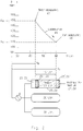
- the casting drive 1 shown in FIG. 1 is used to actuate a casting set 2, consisting of a casting chamber 3 with the molten metal 4 contained therein and a casting piston 5 for inserting the molten metal 4 into a mold cavity, not shown in any more detail.
- the casting piston 5 is connected to the casting drive 1 via a casting piston rod 6.
- the casting drive 1 consists of a front press cylinder 7 and a press piston 8 guided therein, which serves as a drive piston 8 for the associated piston rod 6.
- the press cylinder 7 has a front cylinder chamber 9 and a rear cylinder chamber 10, which are separated by the press piston 8.
- the front cylinder space 9 is connected to a pressure medium connection 11.
- the press cylinder 7 is followed by a multiplier device 12, in which an axially displaceable multiplier piston 13 is arranged.
- the multiplier piston 13 divides the associated cylinder chamber 14 into a front cylinder chamber 15 and a rear cylinder chamber 16.
- the multiplier piston 13 has a first piston rod 17 which extends towards the casting assembly 2 and which extends through the cylinder wall of the multiplier cylinder housing into the rear cylinder chamber 10 of the press cylinder 7 extends.
- the multiplier piston 13 has a rear piston rod 18, which likewise extends over the multiplier cylinder housing into a rear cylinder chamber 19 of an additional connection housing 20.
- the multiplier piston 13 with front piston rod 17 and rear piston rod 18 is penetrated by a central longitudinal bore 21, in which a Check valve 22 is located.
- the present device also works according to the so-called 3-phase system of a cold chamber die casting machine.
- the pressure piston 8 acting directly on the casting piston 5 is pressurized, and during the third working phase the multiplier device is switched on for increased pressure.
- the hydraulic fluid 27, 28 is located below the piston 25, 26, and the pressure medium 29, 30, which is generally designed as nitrogen, is located above the respective piston 25, 26.
- each pressure accumulator 23, 24 has two additional nitrogen bottles 31, 31 'and 32, 32' assigned.
- the pressure accumulator 23 is connected via a connection line 33 and a control valve 34 to the rear cylinder space 19 of the connection housing 20, the pressure accumulator 24 via the connection line 35 and a control valve 36 to the rear cylinder 16 of the multiplier cylinder 14.
- the casting piston is accelerated at high speed for the mold filling stroke. This is done by a changeover point by means of a control cam 41 on the casting piston rod 6.
- the control cam signal is fed via a line 42 to a computer 43, which supplies an output signal or pulse to the shot valve 34 via a line 44. This pulse opens the shot valve 34, so that the hydraulic fluid 27 can suddenly come from the pressure accumulator 23 into the pressure chamber 19 and thus into the pressure chamber 10 to accelerate the plunger 8.
- the casting piston 5 is braked suddenly.
- the full accumulator pressure builds up in the pressure chamber 10 of the press cylinder 7 and also in the chamber 19 of the connection housing 20, the check valve 22 being closed.
- the additional shot valve 36 is opened via the line 45 via the computer 43, so that the hydraulic medium 28 of the second pressure accumulator 24 can be drained via the line 35 into the rear pressure chamber 16 of the multiplier cylinder 14.
- the liquid metal is densified to compensate for the shrinkage of the cast metal.
- the piston rod 17 pushes into the cylinder space 10 in order to increase the pressure.
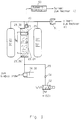
- the position of the operating point for the accumulators 23, 24 is shown in an example in FIG. 2 for a more detailed explanation.
- the operating point of a pressure accumulator can be changed by various influencing variables.
- the volume V is shown on the abscissa and the pressure p of the gaseous pressure medium (nitrogen) is shown on the ordinate, as is present in the cylinder space 29, 30 and the additional tanks 31, 32 in FIG. 1.
- the pressure accumulator 23, 24 is shown in the lower half of the figure in FIG. 2, with a first piston position 25 ', 26' at the precharging point 46 and a second piston position 25, 26 at the operating point 47.
- the two points 46, 47 are indicated by the charging curve 48 connected.
- the piston 25, 26 is in its lowermost position, ie. H. the entire hydraulic fluid 27, 28 has been pressed out of the respective pressure cylinder 23, 24 at the end of the casting process.
- the hydraulic fluid 27, 28 must be pumped back into the pressure accumulators 23, 24 so that the pistons 25, 26 move in these pressure accumulators.
- This displacement of the pistons 25, 26 compresses the gas 29, 30 in the exemplary embodiment according to FIG. 2, for example from a volume of 60 liters to a volume of 44 liters, ie 16 liters of hydraulic medium become in the pressure accumulator 23, 24 pressed in.
- This compression of the pressure medium 29, 30 increases the pressure of this gas from the pressure p0 of z. B. 110 bar to the pressure p B of 150 bar along the charging curve 48.
- the precharge point 46 is therefore characterized by the size V0, p0
- the operating point 47 is characterized by the compressed volume V B and the compressed pressure p B.
- This loading process of the respective pressure accumulator 23, 24 happens along the charging curve 48 in FIG. 2.
- FIG 3 shows an exemplary embodiment for monitoring or regulating the pressure accumulator 23, 24.
- the position of the separating piston 25, 26 in the pressure accumulator can be measured by means of an ultrasonic displacement sensor 49.
- An analog travel signal s K is available at the output of evaluation electronics 50 and is fed to computer 43.
- the gas pressure of the pressure medium 29, 30 or the pressure in the gas bottles 31, 32 is measured by means of a pressure sensor 51 and this value is also fed to the computer 43.
- the superordinate computer can evaluate the exact position of the pressure piston 25, 26 in the operating point 47 or in the precharging point 46 (lower position of the piston 25 ', 26').
- Fig. 3 the hydraulic valve 52 is shown for pressurizing the pressure accumulator 23, 24 with pressure medium by means of a pressure medium pump 53.
- a check valve 54 in a feed line 55 prevents the pressure medium from flowing back.
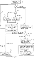
- FIG. 4 An overview of the operation of the computer 43 is shown in FIG. 4.
- an assignment of the pressure p to the actual value of the piston travel s KIst is stored in the computer 43 each time the hydraulic accumulator is loaded . It makes sense here if the values of the piston travel s K are saved at the same pressures as when the reference data were recorded, ie the actual values of the piston travel s KIst are stored as a function of the pressure, for example in the following table: bar mm p s IS 110 s K (0) 115 s K (1) 120 ... 125 ... etc. 150 s K (n)
- This comparison in the computer is shown in FIG. 4 below arrow 61, ie the computer compares the actual values of the piston travel with corresponding setpoints of the piston travel over the distance of the loading curve. It should be noted that this comparison is made via points 1 to n of the measured values of the charging curve.
- Another advantage of the invention is to use a downstream control to evaluate the outputs on the computer in such a way that the pending errors are automatically compensated for without the casting operation being interrupted.
- FIG. 4 shows the essential content of the task of the computer 43, the values of the inputs 56 to 60 being recorded.
- the reference data are stored in the computer
- the tolerance fields are formed and target data are generated
- the actual data 64 are stored and in a further step 65 a comparison is made.
- the outputs on the computer are a piston travel curve s K of the separating piston as a function of the pressure (arrow 61) and an actual setpoint comparison of the precharge pressure p0 at the precharge point 46 (arrow 66).
- the restart takes place when the machine is switched on (position 67).
- an actual setpoint comparison of the precharge pressure p0 is carried out in position 68. If the actual value is not equal to the target value of the precharge pressure (position 69), these values are compared in the computer 43. If p 0 is greater than p 0 target (position 70), a display is shown on screen 61 that p0 is too large. Likewise, a display on the screen 61 takes place during a comparison p 0actual less than p 0set (position 71). Both times, the nitrogen precharge is changed accordingly (position 72 in FIG. 5) or automatic compensation takes place in a separate subroutine.
- This process takes place in a circulation loop 73 until the actual value of the precharge pressure p0 corresponds to the entered target value, so that the program embarks on the computer path 74 from the starting point 68. In position 75 it is accordingly determined that the precharge pressures p0 are in order and that there is a release for the automatic accumulator charging.
- the piston travel s K of the separating piston 25, 26 is monitored as a function of the gas pressure p V (position 76 in the flowchart).
- s K f (p) ).
- the computer detects deviations here, ie sKIst is not equal to s KSoll a display on screen 61 is made under position 77 that the storage bottles 31, 32 are filled, for example, with hydraulic medium due to a leaking separating piston. In this way, the machine is switched off at position 78 to remedy the fault.
- the storage bottles 31, 32 can be emptied from the hydraulic medium manually or by means of an automatic emptying in a subroutine.
- position 79 enables the machine start.
- the flow chart according to FIG. 5 accordingly shows the preparation of the machine with regard to the charging of the pressure accumulators in order to achieve an optimal operating point 47. Both the exact starting point of the precharging point 46 and the achievement of the optimal operating point 47 are ensured.
- the monitoring takes place before the casting cycle is triggered after the release for the machine start (position 79).
- position 80 determines whether the mold is closed. Then the pressure accumulator monitoring starts at position 81.
- position 82 it is first checked whether the pressure p B of the operating point 47 is OK. If it is determined in position 83 that the operating point is too small or too large, then in position 84 if the operating point p B is too small, the display 61 shows that the operating point p B is to be increased by a manual setting change on the die casting machine, or that this pressure p B has to be increased automatically via a subroutine.
- a display is carried out alternatively on the screen 61 as an error display to the effect that the operating pressure p B is to be reduced by manual adjustment change to the die casting machine, which can also be geumbleb Blade again carried out automatically at a p to large operating pressure B. This takes place via the computer loop 86 until the operating point is in order, which is indicated under position 87.
- the precharge pressure p0 is too small, which can have a cause in the gas loss in the pressure accumulator 29 to 32.
- the cause of gas heating is indicated by reference number 92, the cause of gas loss by reference number 93.
- the mold is opened under position 94, which causes the machine start to be interrupted and the precharge pressure p0 can be changed manually or automatically using a subroutine in position 95.
- position 96 releases the metal metering and thus triggers a shot via the shot valves 34, 36.
- FIGS. 7 and 8 each show an embodiment of how the above-mentioned errors can be automatically compensated for.
- a prerequisite for such automatic compensation is the use of the monitoring system previously described in FIGS. 5 and 6.
- Fig. 7 it is shown how the precharge pressure p0 can be automatically set to the correct value.
- the same parts are identified with the same reference numerals as in the previous figures. For this purpose, reference is made in particular to FIGS. 1 and 3.
- Two valves 97, 98 are actuated by means of a control unit (not shown in more detail in FIG. 7) or a control unit connected in parallel to the computer 43.
- a control unit not shown in more detail in FIG. 7
- additional compressed gas is fed from a transportable compressed gas bottle 99 to the pressure accumulators 23, 24 including the gas bottles 31, 32 via the line 100, the precharge pressure ped being able to increase.
- the valve 97 is de-energized by the pressure measuring device 51 so that the access to the pressure bottle 99 is closed.
- the measurement of the actual value of the precharge pressure p0 is accordingly carried out by means of the pressure sensor 51 with evaluation in the computer 43. This measurement signal is fed to the control device (not shown in more detail) in order to actuate the valve 97.
- valve 98 When the valve 98 is activated, compressed gas 29 to 32 can be released into the atmosphere via the line 101 from the gas space 29 to 32 assigned to the pressure accumulator 23, 24.
- valve 98 is again switched off via the control device (not shown) when the measured actual value of the precharge pressure p0 corresponds to the setpoint p 0set . This is again done by means of the pressure sensor 51.
- the arrangement according to FIG. 8 causes the gas cylinders 31, 31 'and 32, 32' of the hydraulic medium 27, 28, which are assigned to the pressure accumulators 23, 24, to be emptied automatically. Due to a possibly leaking separating piston 25, 26 in the pressure accumulators 23, 24, hydraulic medium 27, 28 can reach the compressed gas cylinders 31, 32 via the connecting lines 101.
- the compressed gas bottles 31, 32 can accordingly, as symbolically shown in FIG. 8, partially fill with hydraulic fluid 27, 28. This results in a falsification of the total volume of the gaseous pressure medium.
- valves 102, 103 are provided for the respective gas bottle 31, 32, via which the hydraulic fluid can be drained off via the line 104 or 105.
- the valves 102, 103 may only be switched to passage as long as hydraulic fluid is present in the drain lines 104, 105.
- the drain lines 104, 105 are prevented from running empty by preloaded check valves 106, 107.
- the distinction as to whether there is hydraulic fluid or compressed gas flowing off in the discharge lines 104, 105 can be made, for example, by means of a temperature probe 108, 109. When gas flows at this measuring point, a sudden temperature difference arises, which is used as an evaluation signal and fed to a corresponding control device.
- This control process is indicated schematically with lines 110, 111.
- electronic medium sensors 112, 113 can also be used, whose output signal is in turn fed to the valves 102, 103 via a control device 112 ', 113' via the lines 110, 111.
- the electrical resistance is measured between two sensor pins 114, 115. When the sensor pins 114, 115 are acted upon by hydraulic fluid 27, 28 to be drained from the gas bottles 31, 32, the measured electrical resistance is smaller than when compressed gas flows through this line or the sensor.
- FIG. 8 therefore represents a further advantageous addition to the implementation of the method according to the invention.
- the invention is not restricted to the exemplary embodiment described and illustrated. It was only described as an example for use in a die casting machine. Of course, this can also be applied analogously to an injection molding machine or to a similar hydraulic machine system.
Landscapes
- Engineering & Computer Science (AREA)
- Mechanical Engineering (AREA)
- Supply Devices, Intensifiers, Converters, And Telemotors (AREA)
- Injection Moulding Of Plastics Or The Like (AREA)
- Fluid-Pressure Circuits (AREA)
Applications Claiming Priority (2)
| Application Number | Priority Date | Filing Date | Title |
|---|---|---|---|
| DE4239240A DE4239240A1 (de) | 1992-11-21 | 1992-11-21 | Verfahren zur Regelung und/oder Überwachung eines Hydraulikspeichers |
| DE4239240 | 1992-11-21 |
Publications (2)
| Publication Number | Publication Date |
|---|---|
| EP0599171A1 true EP0599171A1 (fr) | 1994-06-01 |
| EP0599171B1 EP0599171B1 (fr) | 1998-02-04 |
Family
ID=6473381
Family Applications (1)
| Application Number | Title | Priority Date | Filing Date |
|---|---|---|---|
| EP93118436A Expired - Lifetime EP0599171B1 (fr) | 1992-11-21 | 1993-11-15 | Procédé de contrÔle et/ou de régulation d'un réservoir hydraulique |
Country Status (3)
| Country | Link |
|---|---|
| EP (1) | EP0599171B1 (fr) |
| AT (1) | ATE162969T1 (fr) |
| DE (2) | DE4239240A1 (fr) |
Cited By (2)
| Publication number | Priority date | Publication date | Assignee | Title |
|---|---|---|---|---|
| CN108372283A (zh) * | 2018-04-13 | 2018-08-07 | 宁波力劲科技有限公司 | 一种压铸机抽芯装置以及抽芯方法 |
| US10288091B2 (en) | 2013-06-06 | 2019-05-14 | Hydac Electronic Gmbh | Ultrasonic displacement measurement system and method for ultrasonic displacement measurement |
Families Citing this family (1)
| Publication number | Priority date | Publication date | Assignee | Title |
|---|---|---|---|---|
| JP3332871B2 (ja) * | 1998-11-02 | 2002-10-07 | 東芝機械株式会社 | ダイカストマシンの射出制御方法および装置 |
Citations (4)
| Publication number | Priority date | Publication date | Assignee | Title |
|---|---|---|---|---|
| DE2021182A1 (de) * | 1970-04-30 | 1971-11-11 | Weingarten Ag Maschf | Vorrichtung zum Einstellen der beim Druckgiessen erforderlichen unterschiedlichen Presskolbengeschwindigkeiten und -druecke bei Giessmaschinen,insbesondere Kaltkammer-Druckgiessmaschinen |
| JPS5987965A (ja) * | 1982-11-12 | 1984-05-21 | Ube Ind Ltd | 成形機用アキユムレ−タガス圧の制御方法 |
| DE3410228A1 (de) * | 1983-03-23 | 1984-10-04 | Toshiba Kikai K.K., Tokio/Tokyo | Pressdruckueberwachungsverfahren und vorrichtung zur durchfuehrung des verfahrens |
| EP0295831A2 (fr) * | 1987-06-13 | 1988-12-21 | Honda Giken Kogyo Kabushiki Kaisha | Procédé de contrôle hydraulique pour outils à former |
Family Cites Families (5)
| Publication number | Priority date | Publication date | Assignee | Title |
|---|---|---|---|---|
| AT46843B (de) * | 1909-06-07 | 1911-03-10 | Archibald Elmer Hopkins & Olin | Maschine zum Einwickeln von Zuckerwerk. |
| DE2906897A1 (de) * | 1979-02-22 | 1980-09-04 | Bosch Gmbh Robert | Verfahren zur ueberwachung eines gasdruckspeichers und anordnung zu dessen durchfuehrung |
| US4493362A (en) * | 1982-05-27 | 1985-01-15 | Ex-Cell-O Corporation | Programmable adaptive control method and system for die-casting machine |
| JPS5943280A (ja) * | 1982-09-06 | 1984-03-10 | Kobe Steel Ltd | バルブ用アクチユエ−タ |
| US4954063A (en) * | 1988-03-29 | 1990-09-04 | Toshiba Kikai Kabushiki Kaisha | Injection pressure control apparatus for a die cast machine and an injection mold machine |
-
1992
- 1992-11-21 DE DE4239240A patent/DE4239240A1/de not_active Withdrawn
-
1993
- 1993-11-15 EP EP93118436A patent/EP0599171B1/fr not_active Expired - Lifetime
- 1993-11-15 AT AT93118436T patent/ATE162969T1/de not_active IP Right Cessation
- 1993-11-15 DE DE59308105T patent/DE59308105D1/de not_active Expired - Fee Related
Patent Citations (4)
| Publication number | Priority date | Publication date | Assignee | Title |
|---|---|---|---|---|
| DE2021182A1 (de) * | 1970-04-30 | 1971-11-11 | Weingarten Ag Maschf | Vorrichtung zum Einstellen der beim Druckgiessen erforderlichen unterschiedlichen Presskolbengeschwindigkeiten und -druecke bei Giessmaschinen,insbesondere Kaltkammer-Druckgiessmaschinen |
| JPS5987965A (ja) * | 1982-11-12 | 1984-05-21 | Ube Ind Ltd | 成形機用アキユムレ−タガス圧の制御方法 |
| DE3410228A1 (de) * | 1983-03-23 | 1984-10-04 | Toshiba Kikai K.K., Tokio/Tokyo | Pressdruckueberwachungsverfahren und vorrichtung zur durchfuehrung des verfahrens |
| EP0295831A2 (fr) * | 1987-06-13 | 1988-12-21 | Honda Giken Kogyo Kabushiki Kaisha | Procédé de contrôle hydraulique pour outils à former |
Non-Patent Citations (2)
| Title |
|---|
| ERNST BRUNHUBER: "Praxis der Druckgussfertigung", FACHVERLAG SCHIELE & SCHÖN GMBH, BERLIN, 1980 * |
| PATENT ABSTRACTS OF JAPAN vol. 8, no. 197 (M - 324)<1634> 11 September 1984 (1984-09-11) * |
Cited By (3)
| Publication number | Priority date | Publication date | Assignee | Title |
|---|---|---|---|---|
| US10288091B2 (en) | 2013-06-06 | 2019-05-14 | Hydac Electronic Gmbh | Ultrasonic displacement measurement system and method for ultrasonic displacement measurement |
| CN108372283A (zh) * | 2018-04-13 | 2018-08-07 | 宁波力劲科技有限公司 | 一种压铸机抽芯装置以及抽芯方法 |
| CN108372283B (zh) * | 2018-04-13 | 2024-04-19 | 宁波力劲科技有限公司 | 一种压铸机抽芯装置的抽芯方法 |
Also Published As
| Publication number | Publication date |
|---|---|
| DE4239240A1 (de) | 1994-05-26 |
| EP0599171B1 (fr) | 1998-02-04 |
| ATE162969T1 (de) | 1998-02-15 |
| DE59308105D1 (de) | 1998-03-12 |
Similar Documents
| Publication | Publication Date | Title |
|---|---|---|
| DE102017108187B4 (de) | Entleervorrichtung für viskose Stoffe sowie Verfahren hierfür | |
| DE69201769T2 (de) | Hydraulische Polsteranordnung für eine Presse, mit einem Absperrventil zum Abschalten der Energieversorgung der Druckbolzen beim Kontakt des beweglichen Werkzeugs mit dem Werkstück. | |
| EP0946830A1 (fr) | Systeme d'injection de carburant pour moteur a combustion interne | |
| DE3128072A1 (de) | Pruefstand zum pruefen von einspritzduesen | |
| DE2035401A1 (de) | Verfahren und Vorrichtung zum Feststel len der Schweißgute einer Reibungsschweißung | |
| EP3746762B1 (fr) | Dispositif et procédé d'essai de pression | |
| DE3101280A1 (de) | Fahrzeughoehenlageneinstellungs- oder fahrzeugnivelliersystem | |
| DE60018928T2 (de) | Vorrichtung zur sofortigen analyse der einspritzmenge pro einspritzvorgang für eine einspritzanlage von brennkraftmaschinen | |
| EP0576795B1 (fr) | Procédé et dispositif pour commande de processus pour une machine à mouler sous pression | |
| DE19744636C2 (de) | Steuerverfahren für eine Spritzgießmaschine | |
| DE19952708B4 (de) | Einspritzsteuerverfahren und Einrichtung einer Druckgussmaschine | |
| EP0064146B1 (fr) | Système d'injection pour injecter deux combustibles par une seule buse d'injection | |
| DE102016119047B4 (de) | Verfahren zur schnellen Ermittlung einer Kraftstoffmengenänderung | |
| DE10318647A1 (de) | Verfahren zum Einstellen einer Einspritzeitdauer von Kraftstoff durch ein Einspritzventil | |
| EP0599171B1 (fr) | Procédé de contrÔle et/ou de régulation d'un réservoir hydraulique | |
| DE2505648A1 (de) | Einspritzvorrichtung fuer spritzgussmaschinen | |
| DE2544794A1 (de) | Hydraulische presse mit konstantspeicher | |
| DE3325301C2 (de) | Verfahren zum Steuern des Aufbringens und Haltens eines Druckes in einer Reifenvulkanisierpresse | |
| DE102021208552B3 (de) | Verfahren und Steuergerät zum Bestimmen von Drücken in einem Druckmittelzylinder eines Getriebes | |
| DE102004038801B4 (de) | Verfahren und Vorrichtung zur Erkennung von Gaseinschlüssen in einem zähflüssigen Medium | |
| EP2884092B1 (fr) | Procédé et dispositif de réglage du débit d'une soupape d'injection | |
| EP4253765A2 (fr) | Dispositif de maintien d'une alimentation hydraulique d'un véhicule utilitaire | |
| DE2405105A1 (de) | Verfahren und vorrichtung zum absperren von druckspeichern | |
| DE19514644A1 (de) | Preßverfahren für eine Einspritz- und Druckgußvorrichtung | |
| DE3504685C2 (fr) |
Legal Events
| Date | Code | Title | Description |
|---|---|---|---|
| PUAI | Public reference made under article 153(3) epc to a published international application that has entered the european phase |
Free format text: ORIGINAL CODE: 0009012 |
|
| AK | Designated contracting states |
Kind code of ref document: A1 Designated state(s): AT CH DE ES FR GB IT LI NL |
|
| 17P | Request for examination filed |
Effective date: 19940712 |
|
| 17Q | First examination report despatched |
Effective date: 19960617 |
|
| GRAG | Despatch of communication of intention to grant |
Free format text: ORIGINAL CODE: EPIDOS AGRA |
|
| GRAG | Despatch of communication of intention to grant |
Free format text: ORIGINAL CODE: EPIDOS AGRA |
|
| GRAH | Despatch of communication of intention to grant a patent |
Free format text: ORIGINAL CODE: EPIDOS IGRA |
|
| GRAH | Despatch of communication of intention to grant a patent |
Free format text: ORIGINAL CODE: EPIDOS IGRA |
|
| GRAA | (expected) grant |
Free format text: ORIGINAL CODE: 0009210 |
|
| AK | Designated contracting states |
Kind code of ref document: B1 Designated state(s): AT CH DE ES FR GB IT LI NL |
|
| PG25 | Lapsed in a contracting state [announced via postgrant information from national office to epo] |
Ref country code: NL Free format text: LAPSE BECAUSE OF FAILURE TO SUBMIT A TRANSLATION OF THE DESCRIPTION OR TO PAY THE FEE WITHIN THE PRESCRIBED TIME-LIMIT Effective date: 19980204 Ref country code: IT Free format text: LAPSE BECAUSE OF FAILURE TO SUBMIT A TRANSLATION OF THE DESCRIPTION OR TO PAY THE FEE WITHIN THE PRE;WARNING: LAPSES OF ITALIAN PATENTS WITH EFFECTIVE DATE BEFORE 2007 MAY HAVE OCCURRED AT ANY TIME BEFORE 2007. THE CORRECT EFFECTIVE DATE MAY BE DIFFERENT FROM THE ONE RECORDED.SCRIBED TIME-LIMIT Effective date: 19980204 Ref country code: GB Free format text: LAPSE BECAUSE OF FAILURE TO SUBMIT A TRANSLATION OF THE DESCRIPTION OR TO PAY THE FEE WITHIN THE PRESCRIBED TIME-LIMIT Effective date: 19980204 Ref country code: ES Free format text: THE PATENT HAS BEEN ANNULLED BY A DECISION OF A NATIONAL AUTHORITY Effective date: 19980204 |
|
| REF | Corresponds to: |
Ref document number: 162969 Country of ref document: AT Date of ref document: 19980215 Kind code of ref document: T |
|
| REG | Reference to a national code |
Ref country code: CH Ref legal event code: EP |
|
| REF | Corresponds to: |
Ref document number: 59308105 Country of ref document: DE Date of ref document: 19980312 |
|
| RAP2 | Party data changed (patent owner data changed or rights of a patent transferred) |
Owner name: MUELLER WEINGARTEN AG |
|
| ET | Fr: translation filed | ||
| NLT2 | Nl: modifications (of names), taken from the european patent patent bulletin |
Owner name: MUELLER WEINGARTEN AG |
|
| NLV1 | Nl: lapsed or annulled due to failure to fulfill the requirements of art. 29p and 29m of the patents act | ||
| GBV | Gb: ep patent (uk) treated as always having been void in accordance with gb section 77(7)/1977 [no translation filed] |
Effective date: 19980204 |
|
| PG25 | Lapsed in a contracting state [announced via postgrant information from national office to epo] |
Ref country code: AT Free format text: LAPSE BECAUSE OF NON-PAYMENT OF DUE FEES Effective date: 19981115 |
|
| PG25 | Lapsed in a contracting state [announced via postgrant information from national office to epo] |
Ref country code: LI Free format text: LAPSE BECAUSE OF NON-PAYMENT OF DUE FEES Effective date: 19981130 Ref country code: CH Free format text: LAPSE BECAUSE OF NON-PAYMENT OF DUE FEES Effective date: 19981130 |
|
| PLBE | No opposition filed within time limit |
Free format text: ORIGINAL CODE: 0009261 |
|
| STAA | Information on the status of an ep patent application or granted ep patent |
Free format text: STATUS: NO OPPOSITION FILED WITHIN TIME LIMIT |
|
| 26N | No opposition filed | ||
| REG | Reference to a national code |
Ref country code: CH Ref legal event code: PL |
|
| PGFP | Annual fee paid to national office [announced via postgrant information from national office to epo] |
Ref country code: DE Payment date: 20021028 Year of fee payment: 10 |
|
| PGFP | Annual fee paid to national office [announced via postgrant information from national office to epo] |
Ref country code: FR Payment date: 20021123 Year of fee payment: 10 |
|
| PG25 | Lapsed in a contracting state [announced via postgrant information from national office to epo] |
Ref country code: DE Free format text: LAPSE BECAUSE OF NON-PAYMENT OF DUE FEES Effective date: 20040602 |
|
| PG25 | Lapsed in a contracting state [announced via postgrant information from national office to epo] |
Ref country code: FR Free format text: LAPSE BECAUSE OF NON-PAYMENT OF DUE FEES Effective date: 20040730 |
|
| REG | Reference to a national code |
Ref country code: FR Ref legal event code: ST |